
Related Manuals for wtw MIQ/TC 2020 XT


Summary of Contents for wtw MIQ/TC 2020 XT
- Page 1 Operating manual IQ S ENSOR System 2020 XT USB Modular multiparameter measuring system, Terminal/Controller MIQ/TC 2020 XT ba75765e05 04/2012...
- Page 2 Saving the password If access control is enabled for the IQ S and the ENSOR administrator password is lost, quick administrator acces to the IQ S is not possible (access control: see section 5.4). ENSOR To avoid the loss of the password we recommend to create a back-up of the administrator password.
-
Page 3: Table Of Contents
MIQ/TC 2020 XT terminal/controller ........ - Page 4 MIQ/TC 2020 XT terminal/controllers ........
- Page 5 Configuration of the MIQ/TC 2020 XT ........
- Page 6 MIQ/TC 2020 XT terminal/controller ........
-
Page 7: Iq Sensor Net
System 2020 XT USB Overview Overview How to use this system operating manual Structure of the IQ Sensor Net Operating Manual IQ S ENSOR operating manual System Operating Manual (Ring Binder) IQ Sensor MIQ Module MIQ Terminal Operating Operating Operating Manual Manual Manual... -
Page 8: The Iq Sensor Net System 2020 Xt Usb
Overview System 2020 XT USB The IQ S system 2020 XT USB ENSOR 1.2.1 Structure of the system The IQ S is a modular measuring system for online analysis. ENSOR Modular means that the essential functional units of the measuring system are distributed in components that can be individually compiled for special applications. - Page 9 System 2020 XT USB Overview Fig. 1-2 Functional units of the IQ S System 2020 XT USB ENSOR ba75765e05 04/2012 1 - 3...
-
Page 10: Functions In The Iq Sensor Net
Data backup on USB memory device MIQ/TC 2020 XT Data communication (Profibus) MIQ/(A)-PR Data communication (Modbus) MIQ/(A)-MOD Remote data transmission (modem) MIQ/TC 2020 XT + USB RS232 adapter Datalogger IQ software pack Data server IQ software pack Differential sensor System... -
Page 11: Possible Ways To Communicate With The Iq S
System 2020 XT USB Overview 1.2.3 Possible ways to communicate with the IQ S ENSOR Digital communication The IQ S can communicate with humans and machines via ENSOR different interfaces. The following page provides an overview: who can communicate with the IQ S ENSOR ... - Page 12 – Alarm component status messages Human Terminal/controller MIQ/TC 2020 XT + USB memory device Human + PC MIQ/IF232 + IQ software pack MIQ/TC 2020 XT + USB RS232 adapter + null modem cable + IQ software pack...
-
Page 13: Components Of The System 2020 Xt Usb
IQ S . Available are: ENSOR – MIQ/TC 2020 XT for operation of the system from various locations, e.g. calibration of IQ sensors on site (compatible terminals, see section 1.4) – MIQ/T2020 PC software terminals. The connection to the PC can... - Page 14 2020 XT USB: ENSOR Component or resource Maximum number Terminal/controller 1 (registered as a controller) MIQ/TC 2020 XT Sensor locations, can be occupied by: – Single sensors – Double sensors – 0/4-20 mA inputs Terminal locations, can be occupied by: –...
- Page 15 SNCIQ or SNCIQ/UG cable. The following diagram shows an IQ S system with two ENSOR mounting variants (Fig. 1-3). stacked mounting distributed mounting MIQ/TC 2020 XT MIQ/PS MIQ/CR3 MIQ/TC 2020 XT MIQ/JB MIQ/JB Po w...
-
Page 16: Miq Modules
Overview System 2020 XT USB 1.2.5 MIQ modules Some of the IQ S components are so-called MIQ modules ENSOR with different functions. All MIQ modules have a standard housing with the following features (Fig. 1-4): P o w Fig. 1-4 MIQ module Housing Hinge... - Page 17 System 2020 XT USB Overview Module lid with hinge Common characteristics of the MIQ modules Due to its wide opening angle, the lid provides a large space for working inside the module (e.g. for connecting lines to the terminal strip).
-
Page 18: Miq/Tc 2020 Xt Terminal/Controller
Overview System 2020 XT USB MIQ/TC 2020 XT terminal/controller The MIQ/TC 2020 XT can be configured in the IQ S as a ENSOR controller (see section 1.3.1) or as a terminal (see section 1.3.2). Compared to older controllers or terminals, the MIQ/TC 2020 XT provides new functions when operating both as a controller (system 2020 XT USB) and as a terminal. - Page 19 System 2020 XT USB Overview Back Front Fig. 1-5 MIQ/TC 2020 XT terminal/controller Graphical display Status LED Keys Arrow keys Module contacts USB-A interface with cover plate Docking mechanism ba75765e05 04/2012 1 - 13...
-
Page 20: Operation As Terminal/Controller
2020 XT USB system and must therefore permanently remain in the system. The MIQ/TC 2020 XT is connected to the system by docking on the free front cover of an MIQ module. The controller function takes over the following tasks: ... -
Page 21: Operation As A Terminal
Display of components lists (IQ sensors and outputs) Display of the log book entries If the MIQ/TC 2020 XT is registered in the system as a terminal, it is mobile and can be removed at any time. If the main controller of the system fails, the MIQ/TC 2020 XT automatically assumes the job of the failed controller (see section 1.3.3). -
Page 22: Operation As Backup Controller
Overview System 2020 XT USB 1.3.3 Operation as backup controller Automatic backup If the MIQ/TC 2020 XT is configured as a terminal, it has a backup function controller that assumes the basic functions of the IQ S ENSOR controller in the case of its failure. Thus the operating safety of the system is considerably increased. -
Page 23: Usb Interface
System 2020 XT USB Overview 1.3.4 USB interface The USB interface of the MIQ/TC 2020 XT provides the following functions: Connection of a USB memory device for data transmission (see section 4.9) – Measurement data – Calibration data – Configuration data –... -
Page 24: Status Led
MIQ/MC, MIQ/C184 XT) can be used with the MIQ/TC 2020 XT (configured as a terminal) without restrictions. If the MIQ/TC 2020 XT is configured as a controller, the functions of the older systems can be used without any restrictions as well. The new system functions, however, cannot be used by some older components. - Page 25 MIQ/MC or MIQ/C184 You can use the new terminal functions as controller at the new MIQ/TC 2020 XT terminal. MIQ/TC 2020 XT Note: as mobile terminal Data transmission via the USB interface is possible but rather slow as the data first has to be transferred from the con- troller to the terminal.
-
Page 26: Behavior Of The Iq Sensor Net In Case Of Error
Overview System 2020 XT USB Behavior of the IQ S in case of error ENSOR 1.5.1 Behavior of the IQ S in case of power failure ENSOR The system configuration (Settings of sensors and diff. sensors and Settings of outputs and links) is stored permanently ... -
Page 27: Behavior Of The Iq Sensor Net If A Components Fails
If the operating voltage is too low, the LEDs on the MIQ modules extinguish. The blue status LED of the MIQ/TC 2020 XT flashes If active components (e.g. sensors or output modules) cannot be contacted, an entry is made in the log book. The error symbol flashes on the display. -
Page 28: Availability Of The System
Back up the controller function with the aid of a second MIQ/ TC 2020 XT configured as a terminal. The MIQ/TC 2020 XT has a redundant controller function. It maintains all essential functions of the system in the case of a controller malfunction and saves all settings. -
Page 29: Safety Instructions
System 2020 XT USB Safety instructions Safety instructions This operating manual contains essential instructions that must be followed during the commissioning, operation and maintenance of the IQ S system. Thus, it is essential for the operator to read this ENSOR component operating manual before carrying out any work with the system. -
Page 30: Authorized Use
Safety instructions System 2020 XT USB Special user The following installation activities may only be performed by a qualifications qualified electrician: Connection of the MIQ/PS power supply module to the power line (see MIQ/PS module manual). Connection of external, line voltage-carrying circuits to relay contacts (see module manual of the relay output module). - Page 31 System 2020 XT USB Safety instructions Safe operation If safe operation is no longer possible, the IQ S must be ENSOR taken out of operation and secured against inadvertent operation. Safe operation is no longer possible if components: have been damaged in transport ...
- Page 32 Safety instructions System 2020 XT USB 2 - 4 ba75765e05 04/2012...
-
Page 33: Installation
3.1.2 Terminal/Controller The following parts are contained in the scope of delivery of the MIQ/ TC 2020 XT terminal/controller: MIQ/TC 2020 XT Screw to fix the terminal on the MIQ module Operating manual. Requirements of the measurement location... -
Page 34: System Planning
Installation System 2020 XT USB System planning Overview of the Start planning steps Fundamentals of planning - Number and types of required sensors - Measuring locations to be designed - Number of required operating locations - Distances - Infrastructure, process environment etc. Rough planning topology + layout ENSOR... -
Page 35: Basic Requirements For Optimum Installation
System 2020 XT USB Installation Basic requirements for optimum installation 3.4.1 General information The IQ S supplies all components with low voltage as well ENSOR as digital communication via a shielded 2-wire line. Due to this characteristic, the following factors must be taken into account in the planning of an IQ S system: ENSOR... - Page 36 MIQ modules MIQ/JB MIQ/JBR MIQ/CR3 MIQ/C6 MIQ/R6 MIQ/IC2 + 2.2 W per connected WG 20 A2 power supply/isolator MIQ/CHV MIQ/CHV PLUS MIQ/Blue PS MIQ/A MIQ/(A)-PR MIQ/(A)-MOD Terminal, Controller MIQ/TC 2020 XT MIQ/IF232 (+ MIQ/T2020 PC) 3 - 4 ba75765e05 04/2012...
- Page 37 [W] requirement P [W] (sum power supply (component) of the components) modules required 1 MIQ/TC 2020 XT (terminal/controller) + 1 MIQ/TC 2020 XT + 3.0 (terminal) ® + 1 NiCaVis 705 IQ + 8.0 14,0 ® + 1 VisoTurb 700 IQ + 1.5...
-
Page 38: Effect Of The Cable Length
Installation System 2020 XT USB 3.4.3 Effect of the cable length The length of the cables in the IQ S affects ENSOR the operating voltage available for a component the quality of data transmission. Note All information applies to SNCIQ cable material only. As regards the copper wire diameter and dielectric, this cable is especially designed for the combined energy and data transmission via great distances and ensures the lightning protection characteristics stated in chapter 8... - Page 39 L1, L2 and L3 as the cable section L4 is shorter than L = L1 + L2 + L3 MIQ/PS MIQ/24V << MIQ/TC 2020 XT = 150 m L4 = 200 m L2 = 200 m L3 = 300 m Fig.
- Page 40 Installation System 2020 XT USB Checking the power Determine the length of the cable section for the planned supply installation. Determine the sum of the power consumption of all consumers along the cable section (including IQ sensors). Enter both determined values as a point in the following diagram.
- Page 41 System 2020 XT USB Installation Example Problem: Consumers with a total power requirement of 9 W are positioned on a cable section of 650 m. Is the power supply with one power supply module sufficient? At which point must a further power supply module be installed if necessary? Proceeding: ...
-
Page 42: Optimum Installation Of Miq Power Supply Modules
technical protective measures inside the instrument, and exterior protective measures of the installation environment. With WTW online measuring technique, the technical protective measures inside the instrument are already integrated as the so-called lightning protection (see chapter 8 T... - Page 43 System 2020 XT USB Installation 2 The SNCIQ or SNCIQ-UG cable material must be used exclusively. This cable material, particularly the high line cross section of the cable shielding (1.5 mm²), is an important prerequisite for the hazard-free discharging of the surge without inadmissibly high overvoltages developing along the line at the same time that could have a damaging effect on the individual IQ S ENSOR...
- Page 44 Installation System 2020 XT USB 7 The IQ S safety and lightning protection concept is partly ENSOR based on the high-quality protective insulation of the line power supply units and the total system. It does not have or require any protective ground (PG) conductor or earth terminal.
-
Page 45: Connecting System Components
System 2020 XT USB Installation Connecting system components 3.5.1 General information The IQ S system components are connected to form a ENSOR functioning unit in the following ways: Stacked mounting of MIQ modules Up to three MIQ modules can be installed and mechanically connected with one another to form a stack at a single location. -
Page 46: Stacked Mounting Of Miq Modules
Installation System 2020 XT USB 3.5.2 Stacked mounting of MIQ modules: Caution For optimum stability, a maximum of three MIQ modules can be mounted in any one stack. Only one MIQ power supply module may be mounted per module stack. Mounting direction MIQ modules can be stacked on top of one another from both sides. - Page 47 System 2020 XT USB Installation Both installation variants are described below. To dismantle a module stack, proceed in the reverse order to mounting the stack. Variant 1: Stack expansion forwards Preparing the stack mounting Back Front MIQ module MIQ module t a p t f e e lm...
- Page 48 Installation System 2020 XT USB Caution Only use the plastic tapping screws supplied for attaching the contact base. They ensure the correct fit. Attach the contact base (pos. 5 in Fig. 3-5) on the front MIQ module with the two plastic tapping screws (pos. 6). On the front MIQ module, remove the two countersunk screws (pos.
- Page 49 System 2020 XT USB Installation Stacking the MIQ modules Fig. 3-7 Stacking the MIQ modules (variant 1) Fig. 3-8 Closing the enclosure (variant 1) Attach the prepared MIQ module to the lid of the back MIQ module. At the same time, ensure that the two clips on the front MIQ module click into place in the lid of the back MIQ module.
- Page 50 Installation System 2020 XT USB Variant 2: stack expansion backwards Preparing the stack mounting Back Front MIQ module MIQ module t a p t f e e lm r n e t a g u f k n t a n t ie le b t a c...
- Page 51 System 2020 XT USB Installation Caution Only use the plastic tapping screws supplied for attaching the contact base. They ensure the correct fit. Attach the contact base (pos. 6 in Fig. 3-10) on the front MIQ module with the two plastic tapping screws (pos. 7). Premounting the ISO blind nuts Fig.
- Page 52 Installation System 2020 XT USB Stacking the MIQ modules Fig. 3-12 Stacking the MIQ modules (variant 2) Fig. 3-13 Closing the enclosure (variant 2) Attach the prepared MIQ module to the back of the front MIQ module. At the same time, ensure that the two clips on the front MIQ module click into place in the lid of the back MIQ module.
-
Page 53: Distributed Mounting Of Miq Modules
System 2020 XT USB Installation Close the back MIQ module and fix it with the two countersunk screws (pos. 5 in Fig. 3-13). 3.5.3 Distributed mounting of MIQ modules General information The following IQ S cables can be used for distributed ENSOR mounting: ... - Page 54 Installation System 2020 XT USB Preparing the cable Cut off the cable to the required length. ends Remove approx. 45 mm of cable insulation (in the case of the SNCIQ/UG earth cable, remove both the inner and outer insulation). Only for the SNCIQ/UG earth cable: strip the outer insulation for further 35 mm.
- Page 55 System 2020 XT USB Installation SENSORNET 1 SENSORNET 2 SENSORNET 2 SENSORNET 1 SNCIQ SACIQ SNCIQ/UG Fig. 3-15 Connecting cables to the MIQ module Screw the cable gland (pos. 1 in Fig. 3-15) with the sealing ring (pos. 2) into the module housing. Loosen the coupling ring (pos.
- Page 56 Installation System 2020 XT USB Fig. 3-16 Closing the cable opening Screw the remaining cable glands with the sealing rings into the remaining free openings and close them with the enclosed blind plugs (pos. 4 in Fig. 3-16) and tighten the coupling ring (pos.
-
Page 57: Connecting Iq Sensors
System 2020 XT USB Installation 3.5.4 Connecting IQ sensors 1 x SACIQ connection cable (see chapter 9 A Materials required CCESSORIES AND OPTIONS 1 x cable gland with seal The module end of the connection cable already has the sheath removed in the factory and all the wires are fitted with wire end sleeves. - Page 58 Installation System 2020 XT USB Note IQ S cables must always be installed separately at a ENSOR minimum distance of 20 cm from other lines that carry a voltage greater than 60 V. Remove the protective caps from the plug connections of the Connecting the sensor IQ sensor and SACIQ sensor connection cable and keep them to the connection cable...
-
Page 59: Installing Terminal Components
IF232 component operating manual) The terminal component is installed on the lid of any free MIQ module. The MIQ/TC 2020 XT configured as a terminal is docked on the lid of any free MIQ module. If the MIQ/TC 2020 XT is configured as a controller, the MIQ/ TC 2020 XT, as opposed to a mobile terminal (e.g. - Page 60 (pos. 3 in Fig. 3-19). Configuring the MIQ/ During the commissioning of the MIQ/TC 2020 XT at the TC 2020 XT as a mobile IQ S a query appears asking whether the MIQ/TC 2020 XT...
-
Page 61: Installation Of The Miq Modules At The Installation Location
System 2020 XT USB Installation Installation of the MIQ modules at the installation location 3.6.1 General information The IQ S system has a comprehensive program of ENSOR mounting accessories, which can be used to adapt the installation to the most varied requirements. Caution MIQ modules installed outside must always be protected by a sun shield against the effects of the weather (snow, ice and direct... -
Page 62: Mounting On A Mounting Stand With The Ssh/Iq Sun Shield
Installation System 2020 XT USB Caution No contact base may be mounted on the back of the module (danger of short-circuit!) if the module is mounted on a wall, a sun shield, or a top hat rail. 3.6.2 Mounting on a mounting stand with the SSH/IQ sun shield ... - Page 63 System 2020 XT USB Installation Premounting the ISO blind nuts Fig. 3-21 Mounting the sun shield: Premounting the ISO blind nuts Remove the two countersunk screws (pos. 5 in Fig. 3-21) and swing open the module lid. Insert the cheese-head screws (pos. 6 in Fig. 3-21) with the plastic washers in the drilled mounting holes and loosely screw in the ISO blind nuts (pos.
-
Page 64: Mounting Under The Sd/K 170 Sun Shield
Installation System 2020 XT USB Position the MIQ module on the sun shield and fix it into place with the two screws (pos. 6 in Fig. 3-21). Close the module lid and fix it with the two countersunk screws (pos. 5 in Fig. 3-21). 3.6.3 Mounting under the SD/K 170 sun shield If a single MIQ module is to be installed outside, it must be provided with a sun shield that protects it against the effects of weather. - Page 65 System 2020 XT USB Installation SD/K 170 sun shield (see chapter 9 A Materials required CCESSORIES AND OPTIONS The MR/SD 170 mounting kit is also required for mounting the sun shield on a mounting stand or railing (see chapter 9 A CCESSORIES AND OPTIONS ...
-
Page 66: Panel Mounting
Installation System 2020 XT USB 3.6.4 Panel mounting Note The space required on the panel for a module stack is given in the dimension drawings in section 8.3. Note The front MIQ module of the preassembled module stack must be removed in order to install the stack. - Page 67 System 2020 XT USB Installation Push in the two angle brackets - as shown in Fig. 3-24 - into the lateral guides of the MIQ module up to the stop. Tighten the screws (pos. 2). Screw in the screws (pos. 3) until the screws rest snugly against the panel.
-
Page 68: Top Hat Rail Mounting
Installation System 2020 XT USB 3.6.5 Top hat rail mounting THS/IQ kit for top hat rail mounting (see chapter 9 A Materials required CCESSORIES AND OPTIONS Phillips screw driver. Tools Mounting the MIQ module on a top hat rail le b u f k... -
Page 69: Electrical Connections: General Instructions
System 2020 XT USB Installation Electrical connections: General instructions Cable glands All electric cables are fed from below via prepared openings in the enclosure of the MIQ modules. Cable glands with different clamping ranges are included with most MOQ modules to provide sealing between the cable and enclosure as well as for strain relief. - Page 70 Installation System 2020 XT USB General installation Observe the following points when attaching connecting wires to the instructions terminal strip: Shorten all the wires to be used to the length required for the installation Always fit all the ends of the wires with wire end sleeves before connecting them to the terminal strip ...
-
Page 71: Connecting The Voltage Supply
System 2020 XT USB Installation Connecting the voltage supply Note How to connect the voltage supply is comprehensively described in the operating manual of the MIQ power supply module. Commissioning 3.9.1 Topology and terminator switch For failure-free operation, the terminator switches (terminating resistors) must always be set to ON on two MIQ modules. - Page 72 L1, L2 and L3 as the cable section L4 is shorter than L3: Length of the main line = L1 + L2 + L3 MIQ/PS MIQ/24V MIQ/TC 2020 XT << = 150 m L4 = 200 m L2 = 200 m L3 = 300 m Fig.
- Page 73 System 2020 XT USB Installation SN Terminator SENSORNET 2 SENSORNET 1 Fig. 3-28 Terminator switch ba75765e05 04/2012 3 - 41...
-
Page 74: Start Checklist And System Start
Installation System 2020 XT USB 3.9.2 Start checklist and system start Before starting the system, carry out the system check using the following checklist. Always carry out the check before the initial commissioning before any further commissioning if the system has been previously extended or modified. - Page 75 Select the required function for each MIQ/TC 2020 XT. Fig. 3-29 Selecting the instrument type The MIQ/TC 2020 XT will then try to register with the selected functionality on the IQ S . Note that only one controller can...
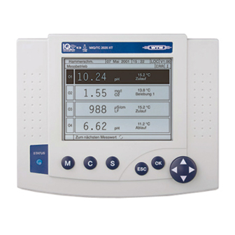
- Page 76 Installation System 2020 XT USB Second start phase As soon as the terminal is successfully initialized, the measured value display appears (fourfold display). In the case of IQ sensors that are not yet providing measured values, "Init" appears temporarily: Fig. 3-31 Display after initialization of the terminal Note Assign a name to each IQ sensor after putting it into operation for the first time so you can identify it more easily.
-
Page 77: Checking The Voltage Supply
System 2020 XT USB Installation 3.9.3 Checking the voltage supply This test should always be performed: after the initial commissioning after any system extension or modification. This test checks the power supply and the communication of the components after the system has been started. Test procedure Check the status of the LEDs on the MIQ power supply modules (Fig. - Page 78 Installation System 2020 XT USB M IQ S TO . 10 N FO D 31 TI FI C ER /C SA C AN r. 9 r. - N Fig. 3-32 Voltage LED on the MIQ module Note You can measure the voltage that is actually available at the MIQ modules or IQ sensors (see section 7.2.2).
-
Page 79: System Extension And Modification
System 2020 XT USB Installation 3.10 System extension and modification 3.10.1 General information The modular structure of the IQ S system makes it easy to ENSOR carry out subsequent extensions and modifications. The system automatically identifies new active modules and includes them in the list of modules. - Page 80 Installation System 2020 XT USB Note If a new component is not included, the maximum number of datasets (active and inactive datasets) may be exceeded. The maximum number of datasets for IQ sensors is 20. For MIQ output modules, the maximum number of datasets (active and inactive datasets) is 8.
-
Page 81: Configuration Of The Miq/Tc 2020 Xt As A Terminal/Controller Or Terminal
MIQ/TC 2020 XT should work as a terminal/controller or just as a terminal. Select the required function for each MIQ/TC 2020 XT. The MIQ/TC 2020 XT will then try to register with the selected functionality on the IQ S . Note that only one controller can... - Page 82 Installation System 2020 XT USB 3 - 50 ba75765e05 04/2012...
-
Page 83: Operation
Operation Operation MIQ/TC 2020 XT terminal/controllers During the initial commissioning of the MIQ/TC 2020 XT, a query appears asking you in which function you want to use the MIQ/ TC 2020 XT in the system. Two configurations can be selected: ... -
Page 84: Overview Of The Operating Elements
MIQ/TC 2020 XT. ENSOR The operating elements on the terminal are described here using the MIQ/TC 2020 XT terminal as an example. Details and differences when using the software terminal can be found in the MIQ/IF232 component operating manual. -
Page 85: Display
System 2020 XT USB Operation 4.1.2 Display The display contains the following information: Fig. 4-2 View of the display Name of the display Name of the terminal and controller function alternately (CONTROLLER or BACKUP CONTROLLER) Date Time User authorization: Simple access control Lock open: Settings are unlocked –... - Page 86 Operation System 2020 XT USB Error symbol If the error symbol flashes, a new or unacknowledged error message is present in the log book that requires immediate action (see section 4.5.3). Info symbol If the info symbol flashes, new or unacknowledged information is present in the log book (see section 4.5.3).
-
Page 87: Keys
System 2020 XT USB Operation Special displays Init Sensor is being initialized during commissioning or if a new IQ sensor is recognized that is not yet giving measured values ---- Invalid measured value Sensor is being calibrated Clean Cleaning system active, sensor is offline Error Sensor is inactive or defective... -
Page 88: General Operating Principles
Operation System 2020 XT USB General operating principles The operation of the IQ S is standardized and user-friendly. ENSOR The arrow keys, <> are use to make a selection – Highlight individual elements in menus, lists and tables, e.g. menu entries, list elements, columns or fields –... -
Page 89: Navigating In Menus, Lists And Tables
System 2020 XT USB Operation 4.2.1 Navigating in menus, lists and tables Using <S>, open the Settings menu. Menus appear in the form of a list on the display, e.g. the Settings menu shown here. Fig. 4-4 100 - Settings Use <>... -
Page 90: Entering Texts Or Numerals
Operation System 2020 XT USB 4.2.2 Entering texts or numerals You can assign names to IQ sensors, MIQ output modules, terminals and locations. Example: Entering a sensor name: Using <S>, open the Settings menu. Use <> to select the menu item, Edit list of sensors. Use <OK>... - Page 91 System 2020 XT USB Operation Fig. 4-6 Edit list of sensors Note The following letters, numerals and special characters can be entered: AaBb..Zz0..9µ%&/()+-=><!?_ °. Select a letter or numeral with <>. Confirm the letter with <OK>. The character appears behind the last letter. Fig.
- Page 92 Operation System 2020 XT USB Add a new character Select the character to be added with <> and confirm with <OK>. Delete the last character Use <> to select the character and confirm with <OK>. Adopt the name Use <>...
-
Page 93: Access To The Iq Sensor Net With Enabled Access Control
System 2020 XT USB Operation Access to the IQ S with enabled access ENSOR control Note Access control is switched off in the delivery condition. No log-in to the IQ S is required. ENSOR As soon as any access control is enabled, access to the IQ S is protected completely or partly. -
Page 94: Simple Access Control
Operation System 2020 XT USB 4.3.1 Simple access control If simple access control is enabled and the system settings are locked, a lock symbol appears on the display. If a closed lock is displayed, the IQ S informs you that settings cannot be changed in the ENSOR protected mode before you can adopt a changed system setting. -
Page 95: Extended Access Control
System 2020 XT USB Operation 4.3.2 Extended access control If extended access control (without instrument block) is enabled, a symbol for the currently enabled access authorization is displayed. Crown: Administrator logged in, all functions allowed Tool: User with authorization for maintenance activities logged in (e.g. calibration) Eye: Viewer without any authorization The relevant symbol is displayed, depending on the currently enabled... -
Page 96: Extended Access Control With Instrument Block
Operation System 2020 XT USB 4.3.3 Extended access control with instrument block If the extended access control with instrument block is enabled, the display of the terminal where the instrument block was enabled only indicates the IQ S logo. ENSOR As soon as a password was entered the symbol for the currenctly active access authorization is displayed. -
Page 97: Display Of Current Measured Values
System 2020 XT USB Operation Display of current measured values Several options can be selected for displaying the measured values: Measured values (1 sensor) The measured value is shown numerically and as a bar graph on the Measured values (1 sensor) display (see section 4.4.1) ... -
Page 98: Displaying A Single Measured Value
Operation System 2020 XT USB 4.4.1 Displaying a single measured value The measured value is shown numerically and as a bar graph on the Measured values (1 sensor) display. Fig. 4-9 Values: all sensors -> Measured values (1 sensor) 4.4.2 Displaying four measured values Up to four measured values of IQ sensors or differential sensors are shown on the display at the same time. -
Page 99: Displaying Eight Measured Values
System 2020 XT USB Operation 4.4.3 Displaying eight measured values Up to eight measured values of IQ sensors or differential sensors are shown on the display at the same time. Fig. 4-11 Values: all sensors -> Measured values (8 sensors) ba75765e05 04/2012 4 - 17... - Page 100 Operation System 2020 XT USB 4.4.4 Displaying recorded measured values If the measured value recording has been activated for an IQ sensor (see section 5.12), the temporal course of the recorded measured values can be displayed numerically and graphically. The following display options are possible: ...
-
Page 101: Displaying Recorded Measured Values
System 2020 XT USB Operation Displaying recorded Switch to the measured value display with <M>. measured values Select an IQ sensor with <>. Using <OK>, open the Display/Options menu. Select one of the display options with <>. Monthly load of selected sensor ... -
Page 102: Display Of The Measured Values Of A Measurement Location Or Of All Iq Sensors In The System
Operation System 2020 XT USB 4.4.5 Display of the measured values of a measurement location or of all IQ sensors in the system As soon as a terminal is docked onto a measurement location, the local measured value display becomes active. The IQ sensors selected for the measurement location appear on the measured value display (see section 5.9). -
Page 103: Messages And Log Book
All messages are recorded in the log book. In addition, a flashing status LED at the MIQ/TC 2020 XT reminds you that there is an error or alarm (see section 1.3.5). 4.5.1 Message types The system differentiates two types of messages: ... - Page 104 Operation System 2020 XT USB Structure of the log book Fig. 4-14 Log book of entire system Message category (error or info symbol) Module that triggered the message. SYS system (controller) S01 IQ sensor (number 01) S?? IQ sensor (inactive, dataset deleted) D01 MIQ output module (number 01) D?? MIQ output module (inactive, dataset deleted) Message code...
- Page 105 ISTS respective component operating manual. Example: Component "141" (MIQ/TC 2020 XT) sends a message with the short Message code II2141 form message "II2". This is an info message (I) of the type Installation (I) with the type number (2). The detailed message text of the short form message (II2) can be found in the log book and in the operating manual of the component that sent it.
-
Page 106: Viewing Detailed Message Texts
Operation System 2020 XT USB Note The detailed message text in the log book contains a precise description of the message code and, if required, any further actions. The detailed message texts can also be found in the component operating manuals of the individual components. Note The log book shows the current status at the point of time that it was opened. -
Page 107: Acknowledge All Messages
System 2020 XT USB Operation Leave the message text with <ESC>. Note Acknowledgment of a new message text in the log book marks the message as read. When all errors or information messages are acknowledged, the symbols no longer flash. With the Acknowledge all messages function you can acknowledge all messages at the same time (see section 4.5.4). -
Page 108: Calibration Data
Operation System 2020 XT USB Calibration data Note Details on calibration are given in the operating manual for the IQ sensor. Each calibration of IQ sensors that are able to be calibrated causes an entry to be made in the log book. Log book entries contain the following information: ... -
Page 109: Calibration History
System 2020 XT USB Operation 4.6.2 Calibration history The calibration history contains the detailed calibration data of the last calibrations. Call up the measured value display with <M>. Using <>, highlight a sensor and confirm with <OK>. The Display/Options menu opens. Using <>, select the menu item, Calibration history of selected sensor and confirm with <OK>. -
Page 110: Status Info Of Sensors And Outputs
Operation System 2020 XT USB Status info of sensors and outputs The display of the instrument status provides a simple overview of the current modes of sensors (sensor info) and outputs in the IQ S ENSOR The status display can be reached in the Settings/Service/List of all components menu (see section 4.7). -
Page 111: General Course When Calibrating, Cleaning, Servicing Or Repairing An Iq Sensor
System 2020 XT USB Operation General course when calibrating, cleaning, servicing or repairing an IQ sensor When an IQ sensor is calibrated, cleaned, serviced or repaired, the maintenance condition for the relevant IQ sensor should always be switched on. In the maintenance condition ... -
Page 112: Maintenance Condition Of Iq Sensors
Operation System 2020 XT USB 4.8.1 Maintenance condition of IQ sensors The following diagram gives you an overview of when an IQ sensor is in the maintenance condition. Maintanance Sensor condition ON cleaning Measured value Measured value manually active Measured value display display display... -
Page 113: Switching On The Maintenance Condition
System 2020 XT USB Operation 4.8.2 Switching on the maintenance condition Switch on the maintenance condition manually when you want to clean, service or repair (remove and replace) an IQ sensor. Call up the measured value display with <M>. Select the sensor you want to switch on the maintenance condition for with <>. -
Page 114: Switching Off The Maintenance Condition
Operation System 2020 XT USB 4.8.3 Switching off the maintenance condition Call up the measured value display with <M>. Select the sensor you want to switch off the maintenance condition for with <>. The display of the sensor in the measured value display flashes. -
Page 115: Data Exchange Via The Usb Interface
System 2020 XT USB Operation Data exchange via the USB interface With the USB interface the MIQ/TC 2020 XT provides a very simple way to Save data of the IQ S on a USB memory device (see ENSOR section 4.9.1) ... - Page 116 Operation System 2020 XT USB Select the data to be saved with <>. Save configuration Measured data storage Log book Calibration history and confirm with <OK>. Only for backing up the measurement data memory: A list of sensors is displayed for which stored measured values are available.
- Page 117 System 2020 XT USB Operation Press <> to highlight the selection of Save and confirm with <OK>. The selected data will be stored on the USB memory device. ba75765e05 04/2012 4 - 35...
-
Page 118: Transmitting Recorded Measurement Data To A Pc
Data transfer via the USB interface (MIQ/TC 2020 XT --> USB memory device --> PC) IQ Sensor Net This method is recommended if the MIQ/TC 2020 XT is configured as terminal/controller. MIQ/TC 2020 XT Note: If it is configured as a terminal, the data is first sent from the controller to the terminal. -
Page 119: Manual Backup Of The System Configuration
60 min. It will then be overwritten with the current status. 4.9.4 Restoring the system configuration The system configuration backed up by the MIQ/TC 2020 XT can be restored onto the main controller. Hence, after replacement of a defective controller, the original system configuration can be quickly restored. - Page 120 MIQ/TC 2020 XT can be used. To transfer the configuration automatically backed up on the MIQ/ TC 2020 XT to a USB memory, operate the MIQ/TC 2020 XT as a controller or backup controller. In this status the configuration data of the backup controller can be backed up onto a USB memory as a manual backup.
-
Page 121: Software Update For Iq S
ENSOR components. The software update is subdivided into language packets. The transfer of the new software version to the MIQ/TC 2020 XT is carried out via a USB memory device. The update packet with the current instrument software for active... -
Page 122: Information On Software Versions
Operation System 2020 XT USB 4.10.1 Information on software versions The system informs you of the current software versions of the individual IQ S components. ENSOR Call up the measured value display with <M>. Using <S>, open the Settings menu. Using <>, select the menu item, Service and confirm with <OK>. -
Page 123: Miq/Tc 2020 Xt In Its Function As Terminal And Backup
4.11 MIQ/TC 2020 XT in its function as terminal and backup controller If the MIQ/TC 2020 XT was configured as a terminal, the integrated controller works as a backup controller. The backup controller saves the system data at regular intervals and is immediately available in the system as a backup controller if the main controller fails. - Page 124 Operation System 2020 XT USB Sequence of Time axis IQ Sensor Net MIQ/TC 2020 XT MIQ/TC 2020 XT memory main controller controller operation (simplified) Regular Regular controller operation terminal operation Controller operation First saving Saving of the system configuration 2 min after...
- Page 125 In normal operation the main controller carries out regular controller Normal operation operation. The MIQ/TC 2020 XT (configured as a terminal) works as a regular terminal. The MIQ/TC 2020 XT (configured as a terminal) backs up the system configuration: –...
- Page 126 Operation System 2020 XT USB If the MIQ/TC 2020 XT (configured as a terminal) receives no more Event: Failure of the main valid telegrams from the main controller for a period of 2 min, it controller takes over the controller operation as a backup controller. The MIQ/ (MIQ/TC 2020 XT TC 2020 XT is reinitialized.
-
Page 127: Settings/Setup
(e.g. sensor, controller, terminal, output module) appear in the standard language, English. To activate the selected system language for this component, a software update of the component is required. Contact WTW. ba75765e05 04/2012 5 - 1... -
Page 128: Configuration Of The Miq/Tc 2020 Xt
After the reset the instrument asks for the operating mode once again (terminal/controller or terminal). Select the required function. The MIQ/TC 2020 XT will then try to register with the selected functionality on the IQ S ENSOR Note... -
Page 129: Terminal Settings
Illumination brightness Illumination brightness (standby) Display contrast Network settings (if the MIQ/TC 2020 XT is configured as a controller only) Using <S>, open the Settings menu. Using <> and <OK>, select and confirm the menu item, Terminal settings -> . - Page 130 Press <> and <OK> to select and confirm a contrast level. Network settings These settings are used to connect the MIQ/TC 2020 XT to a TCP/IP (TCP/IP settings) network. Details on network connection are given in the operating manual ba75790 "Remote connection to the IQ S ENSOR 2020 XT USB".
-
Page 131: Access Control
System 2020 XT USB Settings/setup Access control Use the function Access control to define the safety settings for theIQ S ENSOR The MIQ/TC 2020 XT, configured as a terminal/controller, provides 4 steps of system security: Safety instructions Password-protected functions No access control None... -
Page 132: Simple Access Control (Unlock/Lock Settings)
Settings/setup System 2020 XT USB 5.4.1 Simple access control (Unlock/lock settings) Use the simple access control where the requirements on the security of the system are low or if old and new terminals or controllers are to be used together in the IQ S ENSOR Password protection can be switched on or off with the Unlock/lock... - Page 133 System 2020 XT USB Settings/setup Fig. 5-3 100 - Settings -> Unlock/lock settings Press <> and <OK> to select a function and <OK> to confirm. The dialog window for entering the password opens. Press <> and <OK> to enter the valid password and press <OK>...
-
Page 134: Extended Access Control
Instrument terminal on block Authorization as for Viewer. which the Instrument block active: function was The MIQ/TC 2020 XT is blocked. Only activated the IQ S logo is displayed. ENSOR Access only with password. Switching on the Using <S>, open the Settings menu. - Page 135 System 2020 XT USB Settings/setup Using <>, select the function, Activate extended access control and confirm with <OK>. Authorization and instrument block can be selected. Fig. 5-4 100 - Settings -> Access control -> Extended access control The instrument automatically generates a password for each authorization level.
-
Page 136: Instrument Block
USB memory device. The USB memory device thereby becomes an electronic key. When the electronic key is inserted in the MIQ/TC 2020 XT the authorization level saved there is automatically read out with the associated password. The user of the electronic key is logged onto the system with his authorization level without any further password query. - Page 137 System 2020 XT USB Settings/setup Saving a password on Simple access control an electronic key Connect the USB memory device to the USB-A interface. Using <S>, open the Settings menu. Using <> and <OK>, select and confirm the menu item, Access control -> . The Access control dialog window opens.
-
Page 138: Editing The List Of Sensors
Settings/setup System 2020 XT USB Editing the list of sensors The Edit list of sensors display provides an overview of all IQ sensors, differential sensors and inactive datasets (see section 7.4.2). In the Edit list of sensors display, you can: ... -
Page 139: Changing The Display Position
System 2020 XT USB Settings/setup 5.5.2 Changing the display position The numbering of the sensors is generated by the system. The order of the sensors in the measured value display and in the Edit list of sensors overview can be individually determined. Using <S>, open the Settings menu. -
Page 140: Erasing Inactive Sensor Datasets
Settings/setup System 2020 XT USB 5.5.3 Erasing inactive sensor datasets An inactive dataset for an IQ sensor arises if the controller receives no signals from a registered IQ sensor. The Error display appears on the measured value display instead of a measured value. Inactive datasets can be recognized by a question mark, e.g. -
Page 141: Setting Up Iq Sensors/Differential Sensors
System 2020 XT USB Settings/setup Setting up IQ sensors/differential sensors 5.6.1 Creating a differential sensor A differential sensor is a virtual sensor. It shows the differential value of two IQ sensors that measure the same parameter and have the same settings. -
Page 142: Erasing A Differential Sensor
Settings/setup System 2020 XT USB 5.6.2 Erasing a differential sensor If a differential sensor is no longer required, it can be erased from the list of sensors. Using <S>, open the Settings menu. Using <> and <OK>, select and confirm the menu item, System settings ->... -
Page 143: Adjusting The Settings For Sensors/Differential Sensors
System 2020 XT USB Settings/setup 5.6.3 Adjusting the settings for sensors/differential sensors Sensor settings include the measured parameter, measuring range and, if necessary, compensations. Note General steps for the selection of sensor settings are given below. Details on sensor settings are given in the operating manual for the IQ sensor. -
Page 144: Sensor-Sensor Link (Automatic Inclusion Of An Influence Quantity)
Settings/setup System 2020 XT USB Sensor-sensor link (automatic inclusion of an influence quantity) The Sensor-sensor link function automatically provides a sensor with the measured value of another sensor in the IQ S system. ENSOR Example D.O. sensors measure the D.O. partial pressure and use the solubility Measurement of the D.O. -
Page 145: Establishing A Sensor-Sensor Link
System 2020 XT USB Settings/setup 5.7.1 Establishing a sensor-sensor link Requirements for a The following requirements have to be met for a sensor-sensor link: sensor-sensor link Hardware – A sensor for which an influence quantity can be corrected ® ®... - Page 146 Settings/setup System 2020 XT USB Establishing a link Using <S>, open the Settings menu. Using <><> and <OK>, select and confirm the menu item, System settings -> Sensor-sensor link. The Sensor-sensor link overview opens. The displayed list includes all sensors with which the ®...
- Page 147 System 2020 XT USB Settings/setup Using <><>, highlight a sensor that can be linked, and confirm with <OK>. The sensors are linked. The influence quantity to be linked and the linked sensor are displayed. Leave the system settings with <M>. In the measured value display, the corrected measured value is marked by an asterisk (*).
-
Page 148: Erasing A Sensor-Sensor Link
Settings/setup System 2020 XT USB 5.7.2 Erasing a Sensor-sensor link Using <S>, open the Settings menu. Using <><> and <OK>, select and confirm the menu item, System settings -> Sensor-sensor link. The Sensor-sensor link overview opens. The displayed list includes all sensors with which the ®... -
Page 149: Editing The List Of Outputs
System 2020 XT USB Settings/setup Editing the list of outputs The Edit list of outputs display provides an overview of all outputs, links and inactive datasets (see section 7.4.3). In the Edit list of outputs display, you can: assign output names (see section 5.5.1) and ... -
Page 150: Erasing An Inactive Dataset For An Miq Output Module
Settings/setup System 2020 XT USB Fig. 5-12 Edit list of sensors 5.8.2 Erasing an inactive dataset for an MIQ output module An inactive dataset for an MIQ output module arises if the system receives no signals from a registered MIQ output module. Inactive datasets can be recognized by a question mark, e.g. -
Page 151: Output Links/Settings
System 2020 XT USB Settings/setup Fig. 5-13 Edit list of outputs -> Erase output module Press <> to select Erase output module and confirm with <OK>. The dialog window for the security prompt appears. Press <> to select Erase output module and confirm with <OK>. -
Page 152: Settings For A Measurement Location
Settings/setup System 2020 XT USB Settings for a measurement location Primarily, the settings for a measurement location simplify the calibration of IQ sensors if several IQ sensors of the same type are operated on the system. The option of hiding IQ sensors on the measured value display that are not operated at the measurement location helps to find IQ sensors at the measurement location quickly. - Page 153 System 2020 XT USB Settings/setup Entering the name of a The name of the measurement location is displayed in the line with the measuring location name of the display. 15 characters are available for the name of the measurement location. Press <>...
-
Page 154: Alarm Settings
Settings/setup System 2020 XT USB 5.10 Alarm settings 5.10.1 General information Under this menu item you can specify reactions on certain alarm events. An alarm event is when a certain measured value (limiting value) of a sensor is exceeded or undercut. You can configure up to 20 alarm events. -
Page 155: Setting Up / Editing Alarms
System 2020 XT USB Settings/setup 5.10.2 Setting up / editing alarms Using <S>, open the Settings menu. Using <> and <OK>, select and confirm the menu item, Alarm settings -> . The Alarm link overview dialog window opens. Alarms that have already been set up have entries in the Sensor column. - Page 156 Settings/setup System 2020 XT USB Fig. 5-16 Select Sensor for alarm link To set up a new alarm, select a sensor from the list with <> and confirm with <OK>. The Set alarm link display opens. Fig. 5-17 Set alarm link Edit the setting table.
- Page 157 System 2020 XT USB Settings/setup Alarm links setting table Menu item Selection/Values Explanations Main variable Measured variable Main variable designates the actual measured parameter of the sensor (e.g. Adjoining variable pH, oxygen, etc.). Adjoining variable designates an additional measured parameter (e.g. temperature).
-
Page 158: Alarm Output To Display
Settings/setup System 2020 XT USB 5.10.3 Alarm output to display When an alarm event occurs, a window with a text message appears. Fig. 5-18 Example of an alarm message on the display The alarm message contains the following information: Line 1: Alarm no. -
Page 159: Alarm Output As Relay Action
System 2020 XT USB Settings/setup 5.10.4 Alarm output as relay action The relay outputs of the IQ S can be configured so a relay ENSOR action is triggered when an alarm event occurs (Open or Close). For this the Alarm contact function must be set for the relay output in the Settings of outputs and links. -
Page 160: System Settings
Settings/setup System 2020 XT USB 5.11 System settings System settings include: Language (see section 5.1) Date/Time (see section 5.11.1) Loc. altitude: (see section 5.11.2) 5.11.1 Setting the date and time The real time clock is used for the display of date and time in the measured value display and in log book entries. -
Page 161: Site Altitude / Setting The Medium Air Pressure
Settings/setup Note The clock in the MIQ/TC 2020 XT bridges periods of power failure of up to 24 hours. After a longer power failure, the clock starts precisely at the time of the failure. A message and an entry in the log book provide information on the power failure and the necessity for resetting the clock. -
Page 162: Measured Value Logging
Settings/setup System 2020 XT USB 5.12 Measured value logging With the Measured value logging setting you can record and store measured values of IQ sensors or differential sensors. You can display the stored measured values as a list or ... -
Page 163: Setting The Recording Interval (Dt) And Recording Duration (Dur.)
System 2020 XT USB Settings/setup 5.12.1 Setting the recording interval (dt) and recording duration (Dur.) Using <S>, open the Settings menu. Using <> and <OK>, select and confirm the menu item, Measured value logging -> . The Measured value logging display opens. It contains a list of all sensors and inactive sensors. - Page 164 Settings/setup System 2020 XT USB Note The percentage of the memory blocks not yet allocated is shown on the display. If all memory blocks have already been allocated (Free storage:: 0%), the number of memory blocks allocated to another IQ sensor may have to be reduced. When the number of memory blocks for a sensor is reduced, the memory block with the oldest data is erased.
-
Page 165: Maintenance And Cleaning
System 2020 XT USB Maintenance and cleaning Maintenance and cleaning Maintenance Maintenance activities Component Maintenance IQ sensors Depending on the type of sensor (see the component operating manual of the sensor) Other components No maintenance required Cleaning MIQ modules and Clean components mounted in the open of gross contamination as control units necessary. - Page 166 Maintenance and cleaning System 2020 XT USB 6 - 2 ba75765e05 04/2012...
-
Page 167: What To Do If
System 2020 XT USB What to do if ... What to do if ... Information on errors Log book The IQ S system performs a comprehensive cyclical self ENSOR test during operation. While doing so, the system identifies all states that deviate from normal operation and enters corresponding messages in the log book (information or error message). -
Page 168: Measuring The Voltage
What to do if ... System 2020 XT USB 7.2.2 Measuring the voltage If an MIQ module shows an error condition (both LEDs off), this can be due to the following causes: The voltage supply has been interrupted The available voltage is not sufficient; the voltage is below the warning range. - Page 169 System 2020 XT USB What to do if ... Note Safe voltage measurement is possible on the module contacts on the outside of MIQ/PS and relay output modules (see Fig. 7-1). Front: Tapping points for measuring the voltage ...+ U ...+ U SENSORNET connections on the terminal strip (example): ...+ U...
-
Page 170: Tips For Clearing Errors In The Voltage Supply
What to do if ... System 2020 XT USB 7.2.3 Tips for clearing errors in the voltage supply Note Admissible values for the internal voltage supply (+U) are given in section 8.1. Supply voltage not Cause Remedy present or in the –... - Page 171 – IQ sensor is defective – Test IQ sensor at another measurement location. – If IQ sensor still does not function, contact WTW. Other components – Component is defective – If possible, test component at another measurement location. – If component still does not function, contact WTW.
-
Page 172: Other Errors
What to do if ... System 2020 XT USB Other errors Status LED Cause Remedy of the MIQ/TC 2020 XT – A fault is present Fault remedy according to the flashes logbook: – More detailed information on the current fault and its remedy is given in the logbook (see section 4.5.2) - Page 173 – Terminals such as the – Set simple access control at terminal/controller MIQ/ T2020 (PLUS) are only the MIQ/TC 2020 XT TC 2020 XT recognized by the MIQ/ terminal/controller (see TC 2020 XT terminal/controller if section 5.4.1).
-
Page 174: Replacing System Components
What to do if ... System 2020 XT USB Replacing system components Note It is always possible to replace components and assign a substitute if the software state of the substitute component is as high or higher as the software version of the original component. 7.4.1 Replacing passive components Passive components include all components that the controller cannot recognize. - Page 175 System 2020 XT USB What to do if ... When this number is reached, no further IQ sensor can be installed. If necessary, an inactive dataset has to be erased to make an extension possible. Note The current calibration data of the IQ sensor is always stored in the sensor.
- Page 176 What to do if ... System 2020 XT USB Case 2: The type of sensor is identical Operator intervention is required with the type of sensor in an here. The connected IQ sensor inactive dataset (or several can: inactive datasets), but the serial –...
-
Page 177: Adding And Replacing Miq Output Modules
System 2020 XT USB What to do if ... Select the required option with <> and confirm with <OK>. – If Add new sensor was selected, the system changes directly to the measured value display. As soon as the IQ sensor is ready for operation, it delivers a measured value. - Page 178 What to do if ... System 2020 XT USB Only replace MIQ output modules (all MIQ modules with relay contacts and/or electrical signal outputs) when the IQ S system is ENSOR switched off. Defective MIQ output modules are removed in the reverse order to the installation.
- Page 179 System 2020 XT USB What to do if ... Case 1: The serial number of the The connected MIQ output MIQ output module is identical module is automatically with the serial number in an assigned to the inactive dataset inactive dataset. and starts to operate again.
- Page 180 What to do if ... System 2020 XT USB Fig. 7-4 Add/replace output module Select the required option with <> and confirm with <OK>. – If Add new output module was selected, the system changes directly to the measured value display. –...
-
Page 181: Technical Data
System 2020 XT USB Technical data Technical data General system data Test marks cETLus, CE Ambient conditions Temperature Operation - 20 °C ... + 55 °C (- 4 ... 131 °F) Storage - 25 °C ... + 65 °C (- 13 ... 149 °F) Relative humidity ≤... - Page 182 Technical data System 2020 XT USB Warning A circuit (except for the power supply connections), that is connected to an IQ S component, must not feed any ENSOR voltages or currents that are not allowed. It has to be made sure that the circuit at any time meets all requirements of a Limited circuit or Limited Power as well as of SELV (Safety Extra Low Voltage).
- Page 183 System 2020 XT USB Technical data Note Instructions of how to measure the actual supply voltage on individual IQ S components are given in this operating manual in ENSOR section 7.2 D IAGNOSING FAULTS IN THE VOLTAGE SUPPLY Instrument safety Applicable norms –...
-
Page 184: General Data Of Miq Modules
Technical data System 2020 XT USB General data of MIQ modules Note Technical data on special MIQ modules are given in the respective operating manuals. Dimensions 144.0 52.2 Front view: Side view: 115.0 11.0 70.0 16.5 Rear view: Stack mounting: Fig. - Page 185 System 2020 XT USB Technical data Mechanical Maximum number of 3 plus terminal component construction MIQ modules in a module stack Enclosure material Polycarbonate with 20 % glass fiber Weight Approx. 0.5 kg Type of protection – IP 66 – In accordance with NEMA 4X MIQ modules are not suitable for conduit connection –...
-
Page 186: Miq/Tc 2020 Xt Terminal/Controller
Side view: Front view: 37.0 210.0 43.0 Stacked mounting: 37.0 48.0 Fig. 8-3 Dimension drawing of the MIQ/TC 2020 XT (dimensions in mm) Mechanical Enclosure material ASA (Acrylonitrile Styrene construction Acrylesterpolymer) Weight Approx. 0.9 kg Type of protection – IP 66 –... -
Page 187: Space Required By Mounted Components
System 2020 XT USB Technical data Electrical data Supply voltage Max. 24 VDC via the IQ S (for ENSOR details, see section 8.1 G ENERAL SYSTEM DATA Power consumption 3.0 W Interfaces Type USB-A (USB Host) Air pressure Measuring range (if an 500 mbar ... - Page 188 Technical data System 2020 XT USB Panel mounting Panel mounting Space required for screwdriver Fig. 8-5 Space required for panel mounting (dimensions in mm) FCC Class A Equipment Statement Note: This equipment has been tested and found to comply with the limits for a Class A digital device, pursuant to Part 15 of the FCC Rules.
-
Page 189: Accessories And Options
THS/IQ 480 050 hat rail in accordance with EN 50022 Set for remote transmission MIQ/TM/SET 902 887 Note Other accessories for the IQ S are given in the WTW ENSOR catalog or on the Internet. ba75765e05 04/2012 9 - 1... - Page 190 Accessories and options System 2020 XT USB 9 - 2 ba75765e05 04/2012...
-
Page 191: Indexes
System 2020 XT USB Indexes Indexes On the following pages, you will find the following indexes: Index of all displays (see section 10.1) Explanation of the message codes (see section 10.2) ba75765e05 04/2012 10 - 1... -
Page 192: Index Of All Displays
System 2020 XT USB lists 10.1 Index of all displays This index contains a selection of displays showing important indications or settings. 100 - Settings -> Access control -> Extended access control ..........5-9 100 - Settings -> Unlock/lock settings ................. 5-7 Add/replace output module.................... -
Page 193: Explanation Of The Message Codes
An air pressure value of 1013 mbar is used for air pressure compensation * Component has been removed from the system, insert component again * Component defective, contact WTW EI4141 Max. components of this component type exceeded Danger of system overload... -
Page 194: Info Messages
* Check installation and cable lengths, Follow installation instructions * Set SN terminator switch acc. to operating manual * Check environmental effects * Component defective, contact WTW EI9141 Power failure occurred * Check date and time and, if necessary, adjust them 10.2.2 Info messages... -
Page 195: Index
System 2020 XT USB Indexes 10.3 Index Access control ........... 5-5 Inactive dataset Air pressure ..........5-35 Output module ......5-24, 7-12 Ambient conditions ......3-1, 8-1 Sensors ........5-14, 7-8 Arrow keys ..........4-5 Information ..........4-21 Authorized use .......... 2-2 Initialization .......... - Page 196 Indexes System 2020 XT USB Measurement location .......5-27 Terminal ..........5-3 Output ..........5-23 Time ...........5-34 sensor ..........5-12 Signal amplifier module ......3-9 Terminal ..........5-4 Single sensors ...........1-7 Site altitude ..........5-35 SN terminator switch ......3-39, 3-47 SNCIQ cable ........3-21, 3-22 Obligations of the operator ......2-3 SNCIQ/UG earth cable ....3-21, 3-22 Operating elements ........4-2 Software status ........4-28...
- Page 197 System 2020 XT USB Indexes ba75765e05 04/2012 10 - 7...
- Page 198 Indexes System 2020 XT USB 10 - 8 ba75765e05 04/2012...
-
Page 199: Appendix
System 2020 XT USB Appendix Appendix 11.1 Forgotten the password? (store separately if required) Extended access The administrator can view and change all stored passwords (see control section 5.4). If the IQ S is locked and the administrator password lost, ENSOR you can unlock the system with a master password. -
Page 200: Default Password
Fig. 11-2 System settings -> Display password Quit the display of the password with <OK>. 11.2 Default password Simple access control The password of the MIQ/TC 2020 XT is set to 1000 in the delivery state. 11 - 2 ba75765e05... - Page 202 For more information on how Xylem can help you, go to xyleminc.com. ® Service address: Xylem Analytics Germany Sales GmbH & Co. KG Dr.-Karl-Slevogt-Str. 1 82362 Weilheim Germany Tel.: +49 881 183-325 Fax: +49 881 183-414 E-Mail wtw.rma@xyleminc.com Internet: www.WTW.com Xylem Analytics Germany GmbH Dr.-Karl-Slevogt-Str. 1 82362 Weilheim Germany...
Need help?
Do you have a question about the MIQ/TC 2020 XT and is the answer not in the manual?
Questions and answers