Table of Contents
Advertisement
VT7600F Series
Installation Guide
November 2015
C
ONTENTS
INSTALLATION................................................................................................ 2
Location ......................................................................................................... 2
Installation ..................................................................................................... 2
TERMINAL, IDENTIFICATION AND FUNCTION ............................................... 4
Screw terminal arrangement and wiring ....................................................... 5
TYPICAL APPLICATIONS.................................................................................. 5
Main outputs wiring ...................................................................................... 6
CONFIGURING AND STATUS DISPLAY INSTRUCTIONS ................................... 9
Status display ................................................................................................. 9
USER INTERFACE .......................................................................................... 11
User configuring instructions menu ............................................................ 11
Local keypad interface ................................................................................. 11
1 | 028-0377-03
November 2015
Advertisement
Table of Contents

Related Manuals for Viconics VT7600F Series


Summary of Contents for Viconics VT7600F Series
-
Page 1: Table Of Contents
VT7600F Series Installation Guide November 2015 ONTENTS INSTALLATION....................2 Location ......................2 Installation ..................... 2 TERMINAL, IDENTIFICATION AND FUNCTION ..........4 Screw terminal arrangement and wiring ............5 TYPICAL APPLICATIONS.................. 5 Main outputs wiring ..................6 CONFIGURING AND STATUS DISPLAY INSTRUCTIONS ........9 Status display .................... -
Page 2: Installation
NSTALLATION Remove security screw on bottom of Room Controller cover. Open unit by pulling on bottom side of Room Controller (fig. 1). Remove wiring terminals from sticker. Read FCC ID and IC label installed in cover. Location Should not be installed on an outside wall. - Page 3 12. Re-install cover (top side first) and gently push extra wire length back into hole in wall. 13. Install security screw. When replacing an existing Room Controller, label the wires before removal of the Room Controller. Electronic controls are static sensitive devices. Discharge yourself properly before manipulating and installing the Room Controller.
-
Page 4: Terminal, Identification And Function
ERMINAL DENTIFICATION AND UNCTION Terminal Description Terminal Use Identification 1 – Y2 2 cooling Second cooling stage output. 2 – Y1 1 cool First cooling stage output. 3 – G Fan Fan output. 4 – RC 24VAC hot Power supply of thermostat, hot side. 5 –... -
Page 5: Screw Terminal Arrangement And Wiring
Screw terminal arrangement and wiring VT76XXF Controller Terminals RS SCom OS YPICAL PPLICATIONS 5 | 028-0377-03 November 2015... -
Page 6: Main Outputs Wiring
Main outputs wiring Wiring notes: Note 1: If the same power source is used for the heating stages, install jumper across RC & RH. Maximum current is 2.0 amps. Note 2: If auxiliary output is used to toggle occupancy of the electronic control card inside the equipment, configure the relay parameter (Aux cont) to the N.O. - Page 7 Temperature vs. Resistance Chart for 10 Kohm NTC Thermistor = 10K ±3% - B = 3975K±1.5%) 25°C 25/85°C ºF Kohm ºC ºF Kohm ºC ºF Kohm ºC ºF Kohm ºC ºF Kohm -40 -40 324.3197 -4 94.5149 32 32.1910 68 12.4601 40 104 5.3467 -39 -38 303.6427 -2 89.2521...
- Page 8 S2060A1000; remote averaging duct mounted temperature sensor c/w junction box. This sensor can be used for: • Remote averaging return air temperature sensing with the sensor mounted on the return air duct. • Outside air temperature averaging sensing with the sensor installed in the fresh air plenum.
-
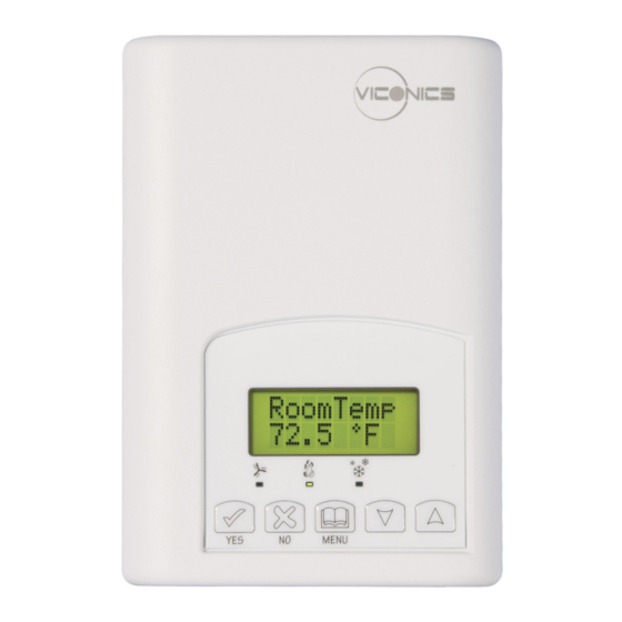
Page 9: Configuring And Status Display Instructions
ONFIGURING AND TATUS ISPLAY NSTRUCTIONS Status display The Room Controller features a two-line, eight-character display. There is a low level backlight that is always active and can only be seen at night. When left unattended, the Room Controller has an auto scrolling display that shows the current status of the system. - Page 10 • The priority for the alarms is as follows: Indicates that the heating is energized by the low limit frost protection room Frost ON temperature setpoint 5.6 °C (42 °F) Indicates that the clock needs to be reset. There has been a power failure SetClock which has lasted longer than 6 hours Indicates that there is a service alarm as per one of the configurable digital...
-
Page 11: User Interface
SER INTERFACE User configuring instructions menu The VT76X6FX series of controllers feature an intuitive, menu-driven, back-lit LCD display that walks users and installers through the configuring steps, making the configuring process extremely simple. This menu is typically accessed by the user to set the parameters such as the clock time set, the schedule time events and the system mode. - Page 12 Viconics Technologies Inc. Tel.: Fax: Toll free: www.viconics.com 12 | 028-0377-03 November 2015...
Need help?
Do you have a question about the VT7600F Series and is the answer not in the manual?
Questions and answers