Advertisement
C
ONTENTS
Installation
Configuring and Status Display Instructions
1 | 028-0228-06
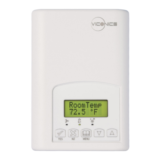
VT7600 Series
Installation Guide
N o ve m b e r 2 0 1 5
2
2
2
4
4
5
5
6
7
9
9
12
12
12
12
Advertisement
Table of Contents

Subscribe to Our Youtube Channel
Related Manuals for Viconics VT7600 Series


Summary of Contents for Viconics VT7600 Series
-
Page 1: Table Of Contents
VT7600 Series Installation Guide N o ve m b e r 2 0 1 5 ONTENTS Installation Location Installation Terminal, Identification and Function Wiring Screw terminal arrangement Main outputs wiring Typical applications Remote sensor accessories Configuring and Status Display Instructions... -
Page 2: Installation
NSTALLATION Remove security screw on bottom of Room Controller cover. Open unit by pulling on bottom side of Room Controller (fig. 1). Remove wiring terminals from sticker. Read FCC ID and IC label installed in the cover. Location Should not be installed on an outside wall. - Page 3 11. Re-Install wiring terminals in correct locations (fig. 3). 12. Re-install cover (top side first) and gently push extra wire length back into hole in wall. 13. Install security screw. If replacing an existing Room Controller, label the wires before removal of the Room Controller.
-
Page 4: Terminal, Identification And Function
ERMINAL DENTIFICATION AND UNCTION Wiring Multistage 1H / 1C Heat Pump Part Part Number VT7656B VT7605B VT7652B VT7600B VT7652A VT7600A VT7652H VT7600H Number Schedule Schedule Top left terminal Top left terminal block block Top right terminal Top right terminal block block Bottom terminal block Bottom terminal block... -
Page 5: Screw Terminal Arrangement
Screw terminal arrangement 3 pole left top connector 5 pole left top connector Y2 Y1 G RC C RH W1 8 pole bottom connector EC AU D1 D2 RS OS MS Scom Main outputs wiring Wiring notes: Note 1: If the same power source is used for the heating stages, install jumper across RC & RH. -
Page 6: Typical Applications
YPICAL APPLICATIONS VT7656B5X00(X) 2 Heat / 2 Cool / Economizer / With Schedule Digital Input #1 Jumper J1 See note 1 Digital Input #2 (previous page) Scom Cool Heat 0-10 Vdc Remote Remote Stage 2 Stage 1 Room Mixed Air Sensor Sensor Cool... -
Page 7: Remote Sensor Accessories
Optional occupancy led Optional override key Wall mounted sensor WIRING EXAMPLE OF SINGLE REMOTE ROOM SENSOR: VT7600 Series 1x S3020W1000 S3010W1000 Remote wiring 1 sensor Remote wiring 1 sensor S2-1 = ON / S2-2 = ON S2-1 = ON / S2-2 = ON... - Page 8 WIRING EXAMPLES OF 2 REMOTE ROOM SENSORS FOR AVERAGING APPLICATIONS: VT7600 Series 2x S3020W1000 2x S3010W1000 VT7600 Series Remote wiring 2 sensors Remote wiring 2 sensors S2-1 = OFF / S2-2 = ON S2-1 = OFF / S2-2 = S c o m...
-
Page 9: Status Display
Temperature vs. resistance chart for 10 Kohm NTC thermistor ºC ºF Kohm ºC ºF Kohm ºC ºF Kohm ºC ºF Kohm ºC ºF Kohm -40 -40 324.3197 -4 94.5149 32 32.1910 68 12.4601 40 104 5.3467 -39 -38 303.6427 -2 89.2521 34 30.6120 70 11.9177 41 106... - Page 10 Sequence of auto-scroll status display: ROOM CLOCK SYSTEM SCHEDULE OUTDOOR ALARMS TEMPERATURE STATUS MODE STATUS TEMPERATURE x.x °C Monday Sys mode Outdoor or °F 12:00 Occupied Service auto x.x °C or°F XX % RH Sys mode Occupied Frost hold Sys mode Unoccup SetClock heat...
- Page 11 Indicates that the heating is energized by the low limit frost protection Frost ON room temperature setpoint 5.6 °C ( 42 °F ) Indicates that the clock needs to be reset. There has been a power failure SetClock which has lasted longer than 6 hours Indicates that there is a service alarm as per one of the configurable digital Service input ( DI1 or DI2 )
-
Page 12: User Interface
NTERFACE User configuring instructions menu The VT7600 series of Room Controller feature an intuitive, menu-driven, back-lit LCD display that walks users through the configuring steps, making the configuring process extremely simple. This menu is typically accessed by the user to set the parameters such as temperature and time events, system mode, fan mode, etc. -
Page 13: November 2015
Viconics Technologies Inc. Tel.: Fax: Toll free: www.viconics.com 13 | 028-0228-06 November 2015...
Need help?
Do you have a question about the VT7600 Series and is the answer not in the manual?
Questions and answers