Table of Contents
Advertisement
Quick Links
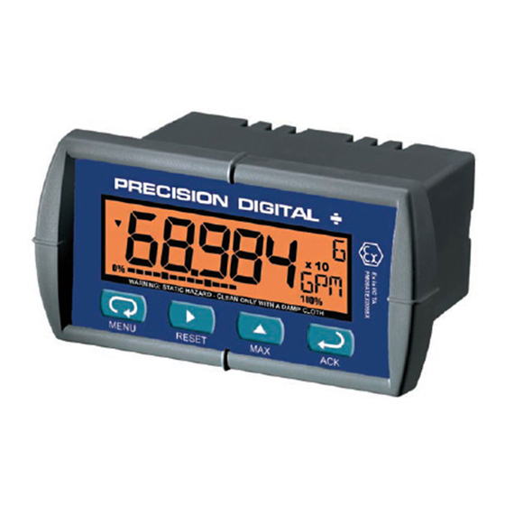
PD684 & PD689 LOOP-POWERED
2 V drop (5.7 V with backlight)
5-Digit LCD, 0.6" (15.2 mm) High
3 Digit Automatic Total Overflow
Rate in Second, Minute, Hour, or Day
Open Collector Pulse or Alarm Output
Custom Engineering Units
20-Segment Bargraph Display
Type 4X, NEMA 4X, IP65 Front
Maximum & Minimum Display
Linear, Square Root, or Programmable Exponent
Non-Volatile Memory – No Battery Needed
PRECISION DIGITAL CORPORATION
89 October Hill Road • Holliston MA 01746 USA
Tel (800) 343-1001 • Fax (508) 655-8990
RATE/TOTALIZERS
Instruction Manual
PD689 only
Loop-
Powered
Backlight
Standard!
www.predig.com
Advertisement
Table of Contents

Related Manuals for PRECISION DIGITAL PD689


Summary of Contents for PRECISION DIGITAL PD689
- Page 1 PD684 & PD689 LOOP-POWERED RATE/TOTALIZERS Instruction Manual PD689 only 2 V drop (5.7 V with backlight) 5-Digit LCD, 0.6" (15.2 mm) High 3 Digit Automatic Total Overflow Loop- Rate in Second, Minute, Hour, or Day Powered ...
- Page 2 Disclaimer The information contained in this document is subject to change without notice. Precision Digital makes no representations or war- ranties with respect to the contents hereof, and specifically disclaims any implied warranties of merchantability or fitness for a particular purpose.
-
Page 3: Introduction
PD684 & PD689 the ideal choice for flow rate & total display applications. ORDERING INFORMATION... -
Page 4: Table Of Contents
PD684 & PD689 Loop-Powered Rate/Totalizers Instruction Manual Table of Contents INTRODUCTION ------------------------------------------------------------ 3 ORDERING INFORMATION --------------------------------------------- 3 SPECIFICATIONS ---------------------------------------------------------- 6 General ------------------------------------------------------------------------------- 6 Input ----------------------------------------------------------------------------------- 7 Open Collector Output ---------------------------------------------------------- 8 PD689 COMPLIANCE INFORMATION ------------------------------- 9 ... - Page 5 QUICK USER INTERFACE REFERENCE GUIDE ---------------- 45 Table of Figures Figure 1. Panel Cutout and Mounting ..........10 Figure 2. PD684 & PD689 Rear View ..........11 Figure 3. PD684 Input Connections with Backlight ......12 Figure 4. PD684 Input Connections without Backlight ....12 Figure 5.
-
Page 6: Specifications
PD684 & PD689 Loop-Powered Rate/Totalizers Instruction Manual SPECIFICATIONS Except where noted all specifications apply to operation at +25°C. General Five digits 0.60" (15.2 mm) high, 7-segment, DISPLAY (-99999 to 99999) automatic lead zero blanking. Four characters 0.25" (6.4 mm) high, 14 segment. -
Page 7: Input
PD684 & PD689 Loop-Powered Rate/Totalizers Instruction Manual Screw terminal connectors: 4.5 lb-in (0.5 Nm) TIGHTENING Mounting screws: 8.0 lb-in max. (0.9 Nm) TORQUE 4.68" x 2.45" x 3.79" (119 mm x 62 mm x 96 mm) OVERALL (W x H x D) DIMENSIONS 5.7 oz (162 g) -
Page 8: Open Collector Output
PD684 & PD689 Loop-Powered Rate/Totalizers Instruction Manual Open Collector Output Isolated open collector, 30 VDC @ 175 mA max. RATING ALARM OUTPUT Assign to rate for high or low alarm trip point. Assign to total for total alarm trip point. -
Page 9: Pd689 Compliance Information
National Differences as they apply for AU, CA, US and KR Special Conditions for Safe Use: The permitted ambient temperature range for the PD689 is -40°C to 65°C. Year of Construction This information is contained within the serial number with the first four digits representing the year and month in the YYMM format. -
Page 10: Installation
PD684 & PD689 Loop-Powered Rate/Totalizers Instruction Manual INSTALLATION There is no need to remove the meter from its case to com- plete the installation, wiring, and setup of the meter. Unpacking Remove the meter from box. Inspect the packaging and con- tents for damage. -
Page 11: Pd684 Connections
Signal connections are made to a four-terminal and a two-terminal re- movable connector. This section is only intended for the PD684. PD689 installation must be performed in accordance with Control Drawing LIM688-2 in order to meet agency approval ratings. Observe all safety regulations. Electrical wiring... -
Page 12: 4-20 Ma Input Connections
PD684 & PD689 Loop-Powered Rate/Totalizers Instruction Manual 4-20 mA Input Connections Input connections are made to a four-terminal connector labeled S+|S-|B+|B-. The loop-powered backlight is an optional configuration and requires a total maximum voltage drop of 5.7 V. The backlight is recom- mended for dim lighting conditions and is enabled when wired as shown in Figure 3. -
Page 13: Open Collector Output Connections
PD684 & PD689 Loop-Powered Rate/Totalizers Instruction Manual Open Collector Output Connections Output connections are made to a two-terminal connector labeled O+|O-. Connect to an input device such as alarm indicator or pulse coun- ter as shown in Figure 5, or drive a relay as shown in Figure 6. -
Page 14: Setup And Programming
PD684 & PD689 Loop-Powered Rate/Totalizers Instruction Manual SETUP AND PROGRAMMING There is no need to recalibrate the meter for milliamps when first received from the factory. The meter is factory calibrated for milliamps prior to shipment. The calibration equipment is certified to NIST standards. -
Page 15: Front Panel Buttons & Status Indicators
PD684 & PD689 Loop-Powered Rate/Totalizers Instruction Manual Front Panel Buttons & Status Indicators MENU RESET Button Description Symbol Status Symbol Bargraph Menu minimum Bargraph Right arrow/Reset 100% maximum Increasing trend Up arrow/Max Decreasing trend Enter/Ack Press the Menu button to enter or exit the Programming Mode at any time. -
Page 16: Main Menu Display Functions & Messages
PD684 & PD689 Loop-Powered Rate/Totalizers Instruction Manual Main Menu Display Functions & Messages The meter displays various functions and messages during setup, pro- gramming, and operation. The following table shows the main menu functions and messages in the order they appear in the menu. - Page 17 PD684 & PD689 Loop-Powered Rate/Totalizers Instruction Manual Display Parameter Action/Setting prog Enter the Program menu Program Enter the Scale menu sCalE Scale Enter the Calibrate menu Calibrate Calibrate input 1 signal or program input 1 inpt1 Input 1 value Program display 1 value...
-
Page 18: Main Menu
PD684 & PD689 Loop-Powered Rate/Totalizers Instruction Manual Main Menu The main menu consists of the most commonly used functions: Setup, Program, and Password. Press Menu button to enter Programming Mode then press Up arrow button to scroll main menu. -
Page 19: Setting Up The Meter (Setup)
PD684 & PD689 Loop-Powered Rate/Totalizers Instruction Manual Setting Up the Meter (setup) The Setup menu is used to select: Rate and total decimal point position Rate and total engineering units display Time base Total conversion factor Manual or automatic total reset function... -
Page 20: Setting The Decimal Point (Dec. P T)
PD684 & PD689 Loop-Powered Rate/Totalizers Instruction Manual Setting the Decimal Point (dec. P T) Decimal point may be set with up to four decimal places or with no dec- imal point at all. Rate decimal and total decimal are programmed indi- vidually. -
Page 21: Setting The Units Display (Units)
PD684 & PD689 Loop-Powered Rate/Totalizers Instruction Manual Setting the Units Display (units) The meter can be set to display a combination of three alphanumeric characters for engineering units (e.g. G/S, LpM) or for identification (e.g. TK3, , L 7). There is also a fourth alphanumeric character located above this row, which supports a degrees symbol and “x10”... -
Page 22: Setting The Time Base (T. B Ase)
PD684 & PD689 Loop-Powered Rate/Totalizers Instruction Manual Setting the Time Base (t. b ase) The meter calculates total based on rate and a time base of units per second, minute, hour, or day. Press the Enter/Ack button, at any time, to accept a setting or Menu button to exit without saving changes. -
Page 23: Manual Or Automatic Total Reset Function (T Rst)
PD684 & PD689 Loop-Powered Rate/Totalizers Instruction Manual Manual or Automatic Total Reset Function (t rST) The meter may be programmed to reset the total either manually using the Reset button or automatically. Manual reset button may be disabled to avoid inadvertent total reset. -
Page 24: Display Rate Or Total Mode (Dsply)
PD684 & PD689 Loop-Powered Rate/Totalizers Instruction Manual Display Rate or Total Mode (Dsply) The meter may be programmed to switch between rate and total with Enter/Ack button press, display rate only, display total only, or to auto- matically toggle between rate and total display every 10 seconds. -
Page 25: Programming The Meter (Prog)
PD684 & PD689 Loop-Powered Rate/Totalizers Instruction Manual Programming the Meter (prog) It is very important to read the following information, before proceeding to program the meter: There is no need to recalibrate the meter for milliamps when first received from the factory. -
Page 26: Scaling The Meter (Scale)
PD684 & PD689 Loop-Powered Rate/Totalizers Instruction Manual Scaling the Meter (sCalE) The 4-20 mA input can be scaled to display the process in engineering units. A signal source is not needed to scale the meter; simply program the inputs and corresponding display values. -
Page 27: Calibrating The Meter (Cal)
PD684 & PD689 Loop-Powered Rate/Totalizers Instruction Manual Calibrating the Meter (Cal) To scale the meter without a signal source refer to Scaling the Meter (sCalE), page 26. The meter can be calibrated to display the process in engineering units by applying the appropriate input signal and following the calibration procedure. -
Page 28: Setting Up The Bargraph (Graph)
PD684 & PD689 Loop-Powered Rate/Totalizers Instruction Manual Setting Up the Bargraph (GrapH) The meter can be set to display a bargraph proportional to the percent- age process reading within a user-defined span. The span is determined by values entered for 0% and 100%. -
Page 29: Setting Up The Password (Pass)
PD684 & PD689 Loop-Powered Rate/Totalizers Instruction Manual Setting Up the Password (pass) The Password menu is used to program a five-digit password to prevent unauthorized changes to the programmed parameter settings. Locking the Meter Enter the Password menu and program a five-digit password. -
Page 30: Unlocking The Meter
PD684 & PD689 Loop-Powered Rate/Totalizers Instruction Manual Unlocking the Meter If the meter is password protected, the correct password must be entered in order to make changes to the parameter settings. Run Mode pass locd 00000 unloc Enter Password Entering the correct five-digit number sets the password to 00000, disa- bling the protection. -
Page 31: Advanced Features Menu
PD684 & PD689 Loop-Powered Rate/Totalizers Instruction Manual Advanced Features Menu To simplify the setup process, functions not needed for most applica- tions are located in the Advanced features menu. Press and hold the Menu button for five seconds to access the Ad- vanced Features of the meter. -
Page 32: Advanced Features Menu & Display Messages
PD684 & PD689 Loop-Powered Rate/Totalizers Instruction Manual Advanced Features Menu & Display Messages The following table shows the Advanced features menu functions and messages in the order they appear in the menu. Display Parameter Action/Setting Enter output menu Output Disable output... -
Page 33: Noise Filter (Flter)
PD684 & PD689 Loop-Powered Rate/Totalizers Instruction Manual For instructions on how to program numeric values see Setting Numeric Values, page 18. Noise Filter (fltEr) Most applications do not require changing this parameter. It is intended to help attain a steady display with an unsteady (noisy) input signal. -
Page 34: Alarm & Pulse Output (Out)
PD684 & PD689 Loop-Powered Rate/Totalizers Instruction Manual Alarm & Pulse Output (out) The PD684 & PD689 are equipped with an NPN open collector output that may be set up for high or low rate alarm trip point, total alarm trip point, or pulse output based on K-factor. - Page 35 PD684 & PD689 Loop-Powered Rate/Totalizers Instruction Manual Alarm Output (alrm) Rate high alarm trip point: program set point above reset point. Rate low alarm trip point: program set point below reset point. Rate alarm deadband is determined by the difference between set and reset points.
-
Page 36: Math Functions (Lnear, Squar, Prog. E , Cutof)
PD684 & PD689 Loop-Powered Rate/Totalizers Instruction Manual Math Functions (lnear, Squar, Prog. E , Cutof) The PD684/PD689 provides a number of functions to condition outputs from linear and non-linear transmitters. Press Enter to Accept Setting Advanced Features Funct Lnear Squar prog. -
Page 37: Internal Calibration (Ical)
The signal source must have a full-scale accuracy of 0.01% or better between 4 and 20 mA in order to maintain the specified accuracy of the PD689. Allow the meter to warm up for at least 15 minutes before performing the internal calibra- tion procedure. -
Page 38: Information Menu (Info)
PD684 & PD689 Loop-Powered Rate/Totalizers Instruction Manual Information Menu (info) The Information menu is located in the Advanced features menu, to access Information menu see Advanced Features Menu, page 31. It shows software and version number. To determine the software ver-... -
Page 39: Rate Or Total Display Readings
PD684 & PD689 Loop-Powered Rate/Totalizers Instruction Manual Rate or Total Display Readings During operation, the front panel buttons control toggling of rate and total display, total reset, and alarm acknowledge. Depending on setup, some displays and functions may not be allowed. -
Page 40: Maximum & Minimum Readings (Max& Min)
PD684 & PD689 Loop-Powered Rate/Totalizers Instruction Manual Maximum & Minimum Readings (Max& MiN) The maximum and minimum (peak & valley) readings reached by the process are stored in the meter since the last reset or power-up. The meter shows MIN or MAX to differentiate between run mode and max/min display. -
Page 41: Mounting Dimensions
PD684 & PD689 Loop-Powered Rate/Totalizers Instruction Manual MOUNTING DIMENSIONS 1.76" (45mm) 2.45" (62mm) 3.2" 0.59" (81mm) (15mm) Figure 7. Meter Dimensions – Side View 2.50" (64mm) 3.61" (92mm) 4.68" (119mm) Figure 8. Case Dimensions – Top View... -
Page 42: Reset Meter To Factory Defaults
PD684 & PD689 Loop-Powered Rate/Totalizers Instruction Manual Reset Meter to Factory Defaults When the parameters have been changed in a way that is difficult to determine what’s happening, it might be better to start the setup pro- cess from the factory defaults. -
Page 43: Factory Defaults & User Settings
PD684 & PD689 Loop-Powered Rate/Totalizers Instruction Manual Factory Defaults & User Settings The following table shows the factory setting for most of the program- mable parameters on the meter. Next to the factory setting, the user may record the new setting for the particular application. -
Page 44: Troubleshooting
PD684 & PD689 Loop-Powered Rate/Totalizers Instruction Manual TROUBLESHOOTING The rugged design and the user-friendly interface of the meter should make it unusual for the installer or operator to refer to this section of the manual. If the meter is not working as expected, refer to the recommendations below. -
Page 45: Quick User Interface Reference Guide
PD684 & PD689 Loop-Powered Rate/Totalizers Instruction Manual QUICK USER INTERFACE REFERENCE GUIDE Display Run Mode Max/Min Decimal Units Setup Time Base Conversion Program Factor Reset Function Password Display Function Locked Unlocked Scale Calibrate Bargraph To Password... - Page 46 PD684 & PD689 Loop-Powered Rate/Totalizers Instruction Manual Pushbutton Function Go to Programming Mode or leave Programming, Advanced Menu Features, and Max/Min Modes. Right Arrow Move to next digit or decimal point position. Reset Total. Up Arrow Move to next selection or increment digit. Go to Max/Min Mode.
-
Page 47: Ec Declaration Of Conformity
PD684 & PD689 Loop-Powered Rate/Totalizers Instruction Manual EC DECLARATION OF CONFORMITY Issued in accordance with ATEX Directive 94/9/EC Precision Digital Corporation Manufacturer: 89 October Hill Rd Ste 5 Holliston, MA 01746 USA PD689 Series Loop Powered Rate/Totalizer Device: FM Approvals Ltd., notified body no. 1725 Notified Body: 1 Windsor Dials, Windsor, Berkshire, UK. - Page 48 PD684 & PD689 Loop-Powered Rate/Totalizers Instruction Manual How to Contact Precision Digital For Technical Support: Call: (800) 610-5239 or (508) 655-7300 Fax: (508) 655-8990 Email: support@predig.com Distributor: Clark Solutions 10 Brent Drive Hudson, MA 01749 Tel: 800-253-2497 Sales@clarksol.com For the latest version of this manual please visit: ...
Need help?
Do you have a question about the PD689 and is the answer not in the manual?
Questions and answers