
Subscribe to Our Youtube Channel
Related Manuals for Belmont Quolis Series


Summary of Contents for Belmont Quolis Series
- Page 1 Quolis 5000 Light Model AL-820 INSTALLATION OPERATION INSTRUCTIONS IMPORTANT After installation is completed, check all the bolts, screws and fasteners to confirm that they are securely fastened.
-
Page 3: Table Of Contents
TABLE OF CONTENTS Page [1] MAJOR PARTS IDENTIFICATION -------------------------------- 1 [2] SPECIFICATIONS ------------------------------------------------------ 1 [3] CLASSIFICATION ------------------------------------------------------ 1 [4] WIRING DIAGRAM ---------------------------------------------------- 2 [5] DIMENSIONS ------------------------------------------------------------ 2 [6] INSTALLATION 6-1. Attach the light assembly to the light pole ----------------------- 3 6-2. -
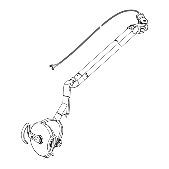
Page 4: Major Parts Identification
[1] MAJOR PARTS IDENTIFICATION (A) Head assembly (B) Balance arm assembly 1. Mode selection switch 2. Touchless Switch 3. Intensity Switch 4. Slot A for Adjusting Tension of Balance Arm 5. Slot B for Adjusting Angle of Head 6. Transformer assembly 7. -
Page 5: Wiring Diagram
[4] WIRING DIAGRAM Mode Selection Switch Manual Sensor Transformer Assembly Green/Yellow Control P.C.B. Faston Slide Connectors Transformer DLT1N2 Black Black Black White Brown Brown Brown 120V Purple 24.9V Orange Brown White Blue 115V Gray 24.1V Black Round Connectors 100V Black 23.6V Blue 0V White... -
Page 6: Installation
[6] INSTALLATION 6-1. Attach the light assembly to the light pole Feed the wire harness coming from the balance arm joint through the light pole. Insert the balance arm joint of the light into the light pole. Fasten with two M6 x 12mm screws. Light Pole M6×12mm Light Assembly... -
Page 7: Attaching Wire Harness From Light Assembly, Transformer Assembly And The Switch Box
6-4. Attaching wire harness from light assembly, transformer assembly and the switch box (1) Attach the connectors of the light assembly wire harness and transformer wire harness. Light assembly wire harness Transformer wire harness (2) As illustrated below, place the wire harness inside the guide. The part with the cable tie should be inside the box. -
Page 8: Attach The Switch Box Cover
6-5. Attach the switch box cover Put all the wires inside the box. Place the switch box cover on the switch box and fix it with two M4 x 6mm screws. Switch box cover M4 x 6 mm 6-6. Wiring between Switch box and transformer assembly (1) Insert the wire harness down through the hole of the swing arm bracket. - Page 9 (3) Attach the transformer assembly by the motor pump of the chair with two M5 x 12mm screws. Also fix the Green/Yellow line from transformer wire harness together with same screw. Transformer wire harness M5 x 12mm Green/Yellow (4) Attach the connectors onto the control PCB of the transformer assembly. Connection with the wire harness for the switch box : 3 pins, 3 pins, 5 pins Connection with the chair’s control PCB : 2 pins 2P...
-
Page 10: Mode Selection Switch
[7] OPERATION 7-1. Mode Selection switch Select the desired - sensor or manual mode with the switch on the box. Sensor : In this mode, the light can be turned on or off with the touch-less switch. Manual : The light is switched on at high intensity (2600FTC/28000 lux). Mode Selection switch : off ○... -
Page 11: Adjustment Of The Tension Of The Balance Arm
[8] ADJUSTMENT OF THE BALANCE ARM Adjustment Bar Slot A (for tension) Tension Adjustment Nut Slot B Hole A (for angle) Tension Adjustment Nut Socket Screw 8-1. Adjustment of the tension of the balance arm Position the angle of the balance arm so the tension adjustment nut becomes visible just under slot A. Turn the nut and adjust the tension with the adjustment bar supplied with the light. -
Page 12: Removal Of The Reflector Cover
[9] REPLACEMENT OF THE BULB CAUTION Make sure the power supply is turned off. Halogen bulb and surrounding parts be hot immediately after the lamp goes off. Wait until they get cool down. IMPORTANT Do not touch glass with bare hand. Halogen bulb surface must be clean. Oil or body moisture will affect bulb span of life. -
Page 13: Inserting A New Bulb
9-3. Inserting a new bulb IMPORTANT Replace halogen lamp only with type JA--24V 60W cbtaainable through your local dealer. (1) At inserting the bulb, make sure that the projection of the bulb holder and the cut-out of the bulb are aligned. -
Page 14: Cleaning
[10] CLEANING CAUTION Allow light to cool prior to cleaning. Use a soft cloth or cotton only to gently clean surfaces. Use of other materials can scratch and damage surfaces. Covers can be cleaned with a soft cloth or cotton moistened with alcohol. The reflector can be cleaned with a soft and dry cloth or cotton with extreme care. - Page 16 NOTE BELMONT EQUIPMENT, Division of Takara Belmont USA, Inc. 101 Belmont Drive Somerset, New Jersey 08873 U.S.A. TEL.:(732) 469-5000 / (800) 223-1192 Fax.:(732)526-6322 / (800) 280-7504 TAKARA CO, CANADA LTD. 2076 S. Sheridan Way, Mississauga, Ont., L5J2M4, Can. TEL.:(905) 822-2755 Fax.:(905)822-6203...
Need help?
Do you have a question about the Quolis Series and is the answer not in the manual?
Questions and answers