
Related Manuals for Hubbell Prime


Summary of Contents for Hubbell Prime
- Page 1 INSTALLATION, OPERATION, AND MAINTENANCE MANUAL FOR CONDENSING GAS STORAGE WATER HEATER BASE MODEL “PRIME”...
-
Page 2: Table Of Contents
Table of Contents INTRODUCTION ..........................4 Operating Principle ..........................4 Safety Information and Precautions ...................... 4 Outline Dimensions ..........................8 Electrical .............................. 10 Gas ............................... 10 2.0 INSTALLATION ............................11 Installation Safety Notes ........................11 Installer Responsibilities ......................12 Water Heater Placement ........................12 Ventilation ............................ - Page 3 Surface Temperature Hi-Limit Cutout Switch ..................44 Removing the Condensate Outlet ......................44 Removing the Fan Assembly ....................... 44 Heat Exchanger ............................ 44 Relief Valve ............................45 Heating Element (If Equipped) ......................45 7.0 REPLACEMENT OF PARTS ........................47 WARRANTY ..............................49 List of Figures ..............................
-
Page 4: 1.0 Introduction
1.0 INTRODUCTION Operating Principle The Hubbell Condensing Gas Water Heater is a Category IV water heater — a water heater that operates with a positive vent static pressure and with a vent gas temperature that may cause excessive condensate production in the vent. The unit uses combusted gas to transfer heat from the air to water. In comparison, traditional electric water heaters use resistive heating elements to directly heat the water. - Page 5 WARNING: If the information in these instructions is not followed exactly, a fire or explosion may result causing property damage, personal injury or death. • Do not store or use gasoline or other flammable vapors and liquids in the vicinity of this or any other appliance.
- Page 6 • Water temperature over 125°F can cause severe burns instantly or death from scalds. • Children, disabled and elderly are at the highest risk of being scalded. • See instruction manual before setting temperature at the water heater. • Feel water before bathing or showering. •...
- Page 7 IN THE STATE OF MASSACHUSETTS ONLY (Check up to date local codes and regulations for other jurisdictions) (a) For all horizontally vented gas fueled equipment installed in every dwelling, building or structure used in whole or in part for residential purposes, including those owned and operated by the Commonwealth and where the side wall exhaust vent termination is less than seven (7) feet above finished grade in the area of the venting, including but not limited to decks and porches, the following requirements shall be satisfied: 1.
-
Page 8: Outline Dimensions
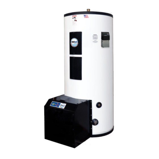
Outline Dimensions Figure 1 - Tank Assembly (55k Btu Unit on top, 110k Unit on bottom) -
Page 9: Table 1- Model Specific Dimensional Data
Table 1- Model Specific Dimensional Data Dimensions (Inches) Floor to Storage Shipping Base Model Tank Overall Overall Floor to Cold Capacity Weight Number Diameter Depth Height Relief Valve Water (Gallons) (lbs.) “A” “B” “C” “D” Inlet “E” GSE55-C-40SL 38.625 31.5 25.25 7.75 GSE55-C-50SL... -
Page 10: Electrical
Electrical • This water heater has a power cord with a standard 120V three-prong plug. • Power cord should be plugged directly into a proper 120V wall outlet. Power strips and extension cords should not be used. • Maximum amperage draw is .7 amps for single heat exchanger model, 1.4 amps for double heat exchanger model. -
Page 11: 2.0 Installation
2.0 INSTALLATION WARNING / CAUTION DO NOT TURN ON THE ELECTRIC POWER SUPPLY to this equipment until heater is completely filled with water and all air has been released. If the heater is NOT filled with water when the power is turned on, the heating elements will burn out (if equipped), and can cause damage to gas heat exchanger. -
Page 12: Installer Responsibilities
Failure to follow instructions could result in explosion causing property damage, serious injury, or death. Ventilation Hubbell Condensing Gas Water Heater is a water heater requiring a “direct venting system” designed for pressurized venting. The exhaust vent must be piped to the outdoors, using the vent materials and rules outlined in this section. -
Page 13: Removing An Existing Water Heater From Common Venting System
commonly vented, it may only be commonly vented with itself and must satisfy all relating safety codes and regulations including use of backflow preventers and increasing pipe diameter when additional exhaust lines connect. It is recommended to increase the pipe diameter to at least 4” PVC if the exhaust lines are combined. DANGER: Vent and Air-inlet are to be piped separately. -
Page 14: Combustion Air-Inlet Contamination
Combustion Air-inlet Contamination Be careful not to locate the air-inlet termination in an area where contaminants can be drawn in and used for combustion. When deciding on a location for the vent and combustion air-inlet terminals on an exterior wall, be sure to allow at least 12 in. -
Page 15: Vent And Air-Inlet Pipe Length Determination
DANGER: Exhaust venting must be supported to reduce strain on piping joints. Failure to follow these instructions may result in damage, serious injury, or death. NOTICE: In Canada, the first 3 ft (915mm) of vent piping must be readily accessible for inspection. Table 3 - Vent/Air-inlet Pipe Materials WARNING: All vent and air-inlet-materials installed on gas fired appliances in CAN/US must meet the... -
Page 16: Termination- Direct Vent Installation
Table 5 - Vent and Air-inlet Pipe Length Determination (Common Vented Double Unit) Number of Elbows (90’s or 45’s) and Equivalent Feet Pipe Length Size 3” 4” NOTICE: 1 foot of piping minimum required before first elbow. NOTICE: The length of one vent pipe (air-inlet or exhaust) may not exceed the length of the other vent pipe by more than 20 equivalent feet. -
Page 17: Figure 3 - Two Pipe Termination (Sidewall)
Sidewall Terminations Figure 3 - Two Pipe Termination (Sidewall) -
Page 18: Figure 4 - Two Pipe Low Profile Termination (Sidewall)
Figure 4 - Two Pipe Low Profile Termination (Sidewall) Figure 5 - Two Pipe Concentric Termination (Sidewall) -
Page 19: Figure 6 - Two Pipe Termination (Roof)
Roof Terminations Figure 6 - Two Pipe Termination (Roof) Figure 7 - Two Pipe Concentric Termination (Roof) -
Page 20: Venting Rules And Guidelines
Combustion air containing chemicals such as chloride, fluoride, bromine, iodine, or dust and debris will cause corrosion damage of the heat exchanger voiding your Hubbell warranty. 3. Vertical Separation: The exhaust must be a minimum of 18 inches above the air inlet, and the air inlet must always be a minimum of 12 inches plus snow allowance above any surface that will support snow (two feet plus snow allowance is highly recommended). -
Page 21: Figure 8 -Venting Below Grade
Figure 8 –Venting Below Grade Figure 9 - Outdoor Venting Guidelines Figure 10 – Existing Chimney Chase Way DANGER: Under no circumstances may an existing chimney or chase-way be used to vent or provide combustion intake air to the water heater. Failure to follow these instructions will result in fire, property damage, serious injury or death. -
Page 22: Table 6 - Vent And Air-Intake Termination Clearances
The quick reference table below is to be read in conjunction with the Venting Rules and Guidelines in this section. The instructions detailed in this section are a combination of Hubbell specific and National Gas Code restrictions. Compliance alone doesn’t insure a satisfactory installation as good common sense must also be applied. -
Page 23: Flammable Solvents And Plastic Piping
Figure 11 - Basic Ventilation Layout Flammable Solvents and Plastic Piping Due to the extremely flammable characteristics of most glues, cements, solvents, and primers used in the process of joining plastic vents and air-inlet pipes explosive solvent vapors must be evacuated from the vent and air-intake prior to start-up. -
Page 24: Condensate Drain
2. Maintain the water heater gas supply shut-off valve in the off position. 3. Disconnect both electrical leads going to the spark ignitor. Refer to the warning regarding Spark Igniter Cable. 4. Turn power on to the water heater and apply a heat demand. 5. -
Page 25: Gas Installation
WARNING: If the combustion chamber has been flooded due to the condensate drain backing up, or for any other reason, the combustion chamber door must be removed and the inside of the water heater must be inspected for component damage. Failure to follow these instructions may result in fire, property damage, serious injury, or death. - Page 26 Ensure that: • The gas line connection to the water heater does not apply any weight to the gas valve. Hubbell recommends using approved flexible gas piping (if acceptable by local codes) to connect the water heater to the gas supply.
-
Page 27: Gas Valve And Burner Set-Up
• All gas piping, including gas components in the water heater, are checked for leaks using a “bubble test” prior to operating the water heater. WARNING: • Strain on the gas valve and fittings may result in vibration, premature component failure and leakage and may result in a fire, explosion, property damage, serious injury, or death. -
Page 28: Figure 16 - Gas Valve Diagram
Figure 16 – Gas Valve Diagram Table 7 - Gas Unit Values Line Pressure (inches W.C.) CO2 (%) CO (ppm) Gas Type Min (3000 Fan Max (7500 Fan Nominal RPM) RPM) Natural 10.5 9.0% 9.5% Gas Line Pressure The water heater gas valve is equipped with a line pressure test port. Use the following procedure to measure the gas line pressure to the water heater to ensure it falls within the range given in Table 7 - Gas Unit Values. -
Page 29: Figure 17 - Gas Valve Schematic
3. Force ¼” ID tubing over the housing of the line pressure test port; install the other end of the tubing to an appropriate line pressure test gauge or manometer. Ensure both ends of the tubing make a tight connection. 4. -
Page 30: Water Piping Installation
Figure 18 – Gas Valve Calibration Figure 19 – Test Port Location 1. Read all safety instructions carefully. 2. Assemble and setup the appliance so that it is operational. 3. Connect all the proper combustion analysis equipment and insert combustion analyzer into ventilation. -
Page 31: Space Heating Application
3. Install a relief valve overflow pipe to a nearby floor drain. 4. When the system requires water for space heating at temperatures higher than required for other uses, a means such as a mixing valve shall be installed to temper the water for those uses in order to reduce scald hazard potential. -
Page 32: Filling The Water Heater
Figure 21 – Mixing Valve Water Piping Installation Diagram Filling the Water Heater 1. Completely close the drain valve. 2. Open the highest hot water faucet to allow all air to escape from piping. 3. Open the valve to the cold water inlet and allow the heater and piping system to completely fill, as indicated by a steady flow of water from the open faucet. -
Page 33: Lighting The Water Heater
3. Ensure that all the above steps are completed. Lighting the Water Heater DANGER: Before Start-up refer to Mandatory Pre-commissioning Procedure for Plastic Venting in section Mandatory Pre-commissioning Procedure for Plastic Venting (PVC or CPVC). Failure to follow these instructions can result in explosion, injury, or death. DANGER: Prior to turning the gas supply on and lighting the water heater, ensure all aspects of installation are complete and in conformance with the instructions provided in this manual, including the Vent/Air-... -
Page 34: Turning Off The Water Heater
WARNING: If the unit fails to light consistently and smoothly, contact Hubbell for technical assistance at 1-203-378-2659. Never allow the water heater to operate if the ignition or operation of the burner is rough or erratic. Failure to follow these instructions may result in serious injury or death. -
Page 35: Button Layout
Table 8 - Status Symbols and Their Meanings Button Layout 5 different buttons are present on the 900DI LCD Display for operating the module, which are positioned the right side of the display. Figure 2 shows the location of the buttons. Figure 23 - Lay-out with Push Buttons The table below describes the button functions. -
Page 36: Temperature Adjustments Via Status Overview
Table 9 - Button Functions Temperature Adjustments via Status Overview Set DHW set point directly via status overview The DHW set point can be directly adjusted in the Status overview. In that case, the following icons are shown, including the set point temperature that is being altered. Table 10 - Important Icon Descriptions When the DHW set point is being directly adjusted via the Status overview and is set below DHW_Setpoint_Min, the display will show “OFF”... -
Page 37: Showing Errors On The Status Overview
DANGER: IF YOU DISCOVER EXTREME HOT WATER COMING FROM THE FAUCET, IMMEDIATELY SHUT OFF THE ELECTRICITY AND GAS AT THE MAIN SWITCH AND CALL COMPETENT SERVICE PERSONNEL. ANY OVERHEATED WATER HEATER IS A POTENTIAL HAZARD TO LIFE AND PROPERTY. DO NOT OPERATE UNTIL THE SOURCE OF THE PROBLEM HAS BEEN DETERMINED AND ELIMINATED. -
Page 38: Installer Menu
Table 12 - Parameter List and Descriptions Installer Menu The table below schematically shows how to enter/operate the Installer menu in some simple steps: Table 13 - Installer Menu Guide The following table shows the available parameters in the Installer menu. -
Page 39: Warnings
Table 14 - Installer Menu Parameter List Warnings Table 15 - Descriptions of Errors If any errors appear on your controller during operation, reference the error messages section of Troubleshooting or call a qualified technician to examine your water heater. -
Page 40: 4.0 Scheduled Maintenance
4.0 SCHEDULED MAINTENANCE WARNING / CAUTION Before performing any maintenance procedure, make certain the power supply is OFF and cannot accidentally be turned on. Freezing The tank should be fully drained in the event the electricity has been turned off and if there is danger of freezing. -
Page 41: 5.0 Troubleshooting
5.0 TROUBLESHOOTING Table 16 - Troubleshooting for Potential Issues Symptom Probable Cause Corrective Action / Remedy Circuit breaker tripped at source Reset circuit breaker. High limit switch tripped Reset high limit switch. Loose wires Tighten wire connections. Have source electrical system checked by Low line voltage an electrician. -
Page 42: Controller Error Messages And Procedures
Temperature and pressure relief valves are designed to operate if the water temperature exceeds 210°F or tank pressure exceeds the pressure rating of the Relief valve safety relief valve. If trouble is excessive Excessive temperature or pressure in discharges temperature, then controller is not shutting tank continuously off at the set point and controller must be... -
Page 43: Blocking Errors
Blocking Errors The following errors are related to the general control functions. Errors are indicated starting with an ‘E’: Table 18 - Blocking Error Codes... -
Page 44: 6.0 Maintenance & Servicing
6.0 MAINTENANCE & SERVICING WARNING / CAUTION Before servicing or replacing any part make sure to turn the power supply switch to the OFF position. Surface Temperature Hi-Limit Cutout Switch 1. Disconnect power from unit. 2. Remove upper access cover. 3. -
Page 45: Relief Valve
7. Remove the condensate outlet. See above. 8. Remove the fan assembly. See above. 9. Disconnect wires from the spark electrode and ionization probe. 10. Remove the 8 bolts and nuts. 11. Remove the heat exchanger and replace with a new one. 12. -
Page 46: Figure 24 - Wiring Diagram Of Burner Control
Figure 24 – Wiring Diagram of Burner Control... -
Page 47: 7.0 Replacement Of Parts
7.0 REPLACEMENT OF PARTS For replacement parts, please reference the list below. All the following parts can be supplied by Hubbell Heater Company. HUBBELL QTY. QTY. DRAWING PART NUMBER DESCRIPTION 110k NUMBER Heat Exchanger V24S0021 GA0101625 Mounting Plate O Ring... - Page 48 FA0304375000 Cable Gland Nut V24S0053 FA1708075000 Condensate Connector V24S0074 FA03083015000 Condensate Nut V24S0054 GP2604005000000 1/2" FPT Brass Term Bolt V24S0055 GP2701005018000 1/2" Gas Line S.S. V24A0020 PVC Exhaust Assembly PVC Exhaust Assembly (Upper) PL041471606 Flue Plug V24S0065 GA16071428 O-Ring SSL 35 x 2.0 MS050000000029 1/2"...
-
Page 49: Warranty
Tank/Heat Exchanger Replacement Policy One Year Limited Parts Warranty Hubbell Heater Company, (hereinafter called the company) offers the following Limited Warranty and Tank Replacement Policy to the purchaser/owner of this stone-lined residential water heater. This Limited Warranty and Tank Replacement Policy is not transferable beyond the original purchaser/owner and is not valid if tank is removed from initial installation site. - Page 50 EXCLUSIONS AND LIMITATIONS Limited Warranty and Tank/Heat Exchanger Replacement Policy are valid only if you comply with the following conditions and limitations: The water heater must be correctly installed according to the installation manual provided with the unit and all applicable local and national codes.
-
Page 51: List Of Tables
List of Figures Figure 1 - Tank Assembly (55k Btu Unit on top, 110k Unit on bottom) ............8 Figure 2 - Ventilation Connections ......................... 13 Figure 3 - Two Pipe Termination (Sidewall) ....................17 Figure 4 - Two Pipe Low Profile Termination (Sidewall) ................18 Figure 5 - Two Pipe Concentric Termination (Sidewall) ................ - Page 52 Table 16 - Troubleshooting for Potential Issues ....................41 Table 17 - Lockout Error Codes ........................42 Table 18 - Blocking Error Codes ........................43...
Need help?
Do you have a question about the Prime and is the answer not in the manual?
Questions and answers