
Related Manuals for Hubbell HD


Summary of Contents for Hubbell HD
- Page 1 INSTALLATION, OPERATION AND MAINTENANCE MANUAL FOR ELECTRIC DEIONIZED / RO WATER HEATER ELECTRIC HEATER COMPANY BASE MODEL “ HD ” ANSI/NSF5 2015 Edition...
- Page 2 HUBBELL ELECTRIC HEATER COMPANY 45 SEYMOUR STREET P.O. BOX 288 STRATFORD, CT 06615 PHONE: (203) 378-2659 FAX: (203) 378-3593 INTERNET: http://www.hubbellheaters.com -- IMPORTANT -- Always reference the full model number and serial number when calling the factory. WARNING / CAUTION 1.
-
Page 3: Table Of Contents
TABLE OF CONTENTS SECTION TITLE PAGE No. GENERAL DESCRIPTION AND CONSTRUCTION INSTALLATION AND START-UP SCHEDULED MAINTENANCE AND OPERATION TROUBLESHOOTING SERVICING AND REPLACEMENT OF PARTS SERVICE PARTS LIST TORQUE VALUES VIII WARRANTY INFORMATION... -
Page 4: General Description And Construction
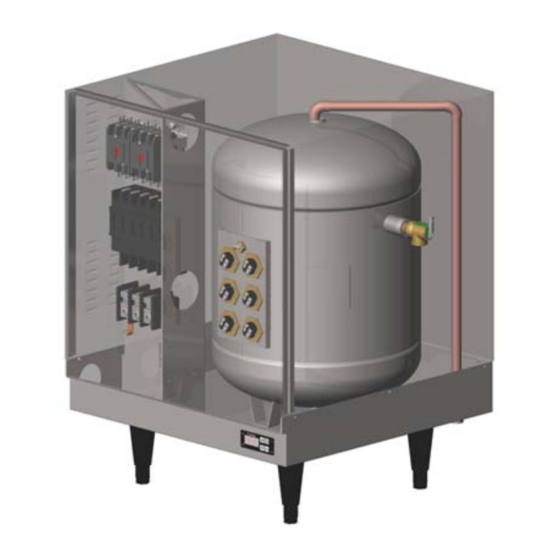
SECTION I - GENERAL DESCRIPTION AND CONSTRUCTION GENERAL DESCRIPTION This book describes a packaged electric water heater designed for use in deionized (DI) or reverse osmosis (RO) water applications. The complete assembly consists of the storage tank, immersion electric heating element(s), electronic control module, safety relief valve, magnetic contactor(s), and any other required electrical operating control. - Page 7 CONSTRUCTION TANK The storage tank is designed, manufactured, and stamped in accordance with ASME Section VIII Division 1. The tank is constructed of type 316L stainless steel and fabricated by all welded construction and is designed for a maximum allowable working pressure of 150 psi (225 psi test pressure).
-
Page 8: Installation And Start-Up
OPTIONAL EQUIPMENT Slide Brackets Available for the HD6 Model only, these brackets allow for mounting the water heater under a counter. See slide bracket diagram on page 9 for details. Legs In lieu of the standard black plastic legs, optional adjustable legs are available in stainless steel, die-cast nickel plated, and floor mount stainless steel. - Page 9 1. Enter the base through the factory cut KO’s with properly sized feeder leads, See Wiring Chart. Single-phase installations require two (2) leads. All Hubbell 3-phase heaters are intended for use with a 3-wire delta system plus ground. No neutral is...
- Page 10 required. For a 4-wire plus ground system, install 3 legs of power plus the ground and terminate the neutral leg. 2. Install these power leads into the box lugs on the power distribution block or magnetic contactor, as required. 3. Connect incoming ground wire to ground lug supplied. 4.
- Page 11 (when the configuration is set to manual reset). 2. This alarm can be wired to the J4 connector on the control board as shown below. To facilitate this installation, an optional adapter, Hubbell P/N PLUG ADAPTER J4, can be purchased to provide wire connections.
- Page 12 Volt Ph Breaker Power Feed Diagram Resistance Wire Wire Size Draw Draw or Fuse Wire Size (Ohms) Size Size Size 14.4 ½" 1(NT)-HD 12.5 12.5 ½" 1(NT)-HD 19.8 19.8 ½" 1(NT)-HD 25.0 25.0 ½" 1(NT)-HD 19.2 19.2 10.8 ½" 1(NT)-HD 16.7...
- Page 13 Breaker Power Feed Diagram Resistance Wire Wire Size Draw Draw or Fuse Wire Size (Ohms) Size Size Size 72.1 72.1 1" 4 (DB)-HD 41.6 41.6 ¾" 10(NT)-HD 62.5 62.5 1" 4-HD 36.1 36.1 ½" 10(NT)-HD 22.9 22.9 19.3 ½" 10(WT)-HD 18.0...
- Page 14 Breaker Power Feed Diagram Resistance Wire Wire Size Draw Draw or Fuse Wire Size (Ohms) Size Size Size 195.0 65.0 2" 6A-HD 112.6 56.3 1¼" 12(NCB)-HD 168.8 56.3 1½" 6A-HD 40.5 97.4 48.7 1" 12(NCB)-HD 60.8 60.8 1" 13(WT)-HD 48.7 48.7...
- Page 17 6A-HD 3A-HD Control Module & Display Control Module & Control & Hi-Limit Display Probe Control & Hi-Limit Leak Detection Probe Probe Leak Detection Probe L1 L2 L3 12-HD Control Module & Display Control & Hi-Limit Probe Leak Detection Probe 17-HD...
- Page 18 L1 L2 L3 16(WT)-HD Control Module & Display Control & Hi-Limit Probe Leak Detection Probe L1 L2 L3 16(CBWT)-HD Control Module & Display Control & Hi-Limit Probe Leak Detection Probe 18-HD L1 L2 L3 Control Module & J3 J2 Display Control &...
- Page 19 Typical HD6 Plumbing Connections (Rear View) Typical HD16 (1-58 kW) Plumbing Connections (Front View)
-
Page 20: Scheduled Maintenance And Operation
Typical HD16 (64-90 kW) Plumbing Connections (Front View) SECTION III – SCHEDULED MAINTENANCE AND OPERATION WARNING / CAUTION Before performing any maintenance procedure, make certain the power supply is turned OFF and cannot accidentally be turned on. MAINTENANCE AND OPERATION The water heater is automatic in its operation. - Page 21 i. Wait 5 seconds without pushing any buttons or press the UP and DOWN buttons simultaneously. 3. To view the number of operational hours (the number of hours when a contactor is pulled in) and software version: a. Press the UP and DOWN arrows simultaneously to enter setpoint change mode. b.
- Page 22 5. To reset any high-limit, no probe, or low water (when in manual reset mode) fault condition, press the RESET button. 6. Display a. By default the display will show the setpoint of the heater. b. The decimal points on the display, as shown below, indicate that the controller is calling for a contactor to pull in.
-
Page 23: Troubleshooting
i. Place limed ends of the heating element in a de-limer solution, designed for potable water applications, and allow lime to dissolve. Do not allow de-limer to contact heating element terminals. g. Other scale removal i. Silicates, sulfates, and aluminates must be removed by scraping or other mechanical means. - Page 24 LOW WATER CUT-OUT 1. Due to the low resistivity of DI/RO water, a 316L stainless steel float type low water cut- out is supplied in lieu of a conductivity type. This device will help protect the elements from energizing when there is insufficient water in the tank. The float type low water cut- out will disengage the control circuit during low/no water conditions and will auto-reset when the water reaches a safe level.
- Page 25 Symptom Probable Cause Corrective Action Temperature and Unit is overheating due See the ‘P65SS Probe Troubleshooting’ pressure relief valve to improper P65SS section. opens and/or high probe calibration. limit temperature Unit is overheating due See the ‘Magnetic Contactor Troubleshooting’ error occurs. section.
- Page 26 CONTROL BOARD (T1000) / DISPLAY (TD1000) TROUBLESHOOTING 1. Verify proper power supply voltage between each phase (L1 to L2, L2 to L3, and L1 to L3). The power supply voltage should match the voltage listed on the heater nameplate. If voltage is incorrect, check main supply wiring or replace unit with proper heater. 2.
- Page 27 voltage is present, check for voltage across the contactor coil. If voltage is present at the contactor coil, replace the magnetic contactor. If no voltage is present, verify that the heater is wired according to the proper wiring schematic for the unit. P65SS PROBE TROUBLESHOOTING 1.
-
Page 28: Vservicing And Replacement Of Parts
Terminal Connections #220 Viton O-Ring 8. Install new #220 Viton o-ring gasket and install new heating element. NOTE: Hubbell recommends lubricating the o-ring with Parker O-Lube prior to installation. 9. Rewire element according to the wiring diagram as shown in the Section II. - Page 29 Probe Ground (J7) Display Cable Leak Detection Wire (J2) Expansion (J1) Ground Wire (J8) (D1) Probe Cable (J3) Alarm Relay (J4) Power Wire (Common, White) Connector (J5) Power Wire (Black) Wire to #1 Contactor (yellow) Wire to #2 Contactor (red) Note: Probe connector J3 comes filled with a dielectric gel that should remain in the connector.
- Page 30 5. Drain water from tank. 6. Remove the thermowell from tank using a 13/16” socket. 7. Install new #115 Viton o-ring gasket and install new thermowell. NOTE: Hubbell recommends lubricating the o-ring with Parker O-Lube prior to installation. WARNING: Do not remove the jam nut.
- Page 31 LOW WATER SWITCH 1. Disconnect power from unit. 2. Shut off incoming water supply. 3. Attach hose to drain connection. 4. Lift manual release lever on relief valve to let air into system or break union on outgoing water line. 5.
-
Page 32: Service Parts List
SECTION VI – SERVICE PARTS LIST Category Description Volts Ohms Hubbell P/N Accessories Plastic Legs (Price each, 4 Req'd.) AP61-4003-C Nickel Plated Legs (Price each, 4 Req'd.) AE61-4002-C Stainless steel adjustable legs (Price each) A50-5048-C Floor Mount Legs S/S (Price each, 4 Req'd.) - Page 33 SERVICE PARTS LIST (cont.) Category Description Volts Ohms Hubbell P/N Misc. Electrical Control Board T1000 Digital Display Module (with overlay and HD16 Extension) TD1000 HD16 Ribbon Cable Extension RIBBON CABLE J16 Display Overlay OVERLAY J MODEL Probe Sensor P65SS Probe Thermowell (includes #115 Buna-N O-Ring)
-
Page 34: Torque Values
SECTION VII – TORQUE VALUES Torque Torque Part Wire Size (in•lbs) (ft•lbs) Element to Tank Wire to 1.25 Element Probe to Tank Wire to Ground KA8C 2.08 KA4C 3.75 #14-#10 2.92 Wire to Circuit 3.33 Breaker #6-#4 3.75 Transformer 1.25 Wire to Control 0.29 Board... -
Page 35: Warranty Information
(45 Seymour Street Stratford, CT 06615) for replacement or repair. Hubbell reserves the right to accept or reject any such claim in whole or in part. Hubbell will not accept the return of any product without prior written approval from Hubbell, and all such approved returns shall be made at Buyer's sole expense. - Page 36 P.O. BOX 288 STRATFORD, CT 06615-0288 PHONE: (203) 378-2659 FAX: (203) 378-3593 INTERNET: http://www.hubbellheaters.com/...
Need help?
Do you have a question about the HD and is the answer not in the manual?
Questions and answers