
Subscribe to Our Youtube Channel
Related Manuals for Hubbell PS Series


Summary of Contents for Hubbell PS Series
- Page 1 INSTALLATION, OPERATION AND MAINTENANCE MANUAL FOR POINT OF USE STEAM FIRED WATER HEATER ELECTRIC HEATER COMPANY BASE MODEL “ PS ” Edition 2019...
- Page 2 HUBBELL ELECTRIC HEATER COMPANY P.O. BOX 288 STRATFORD, CT 06615 PHONE: (203) 378-2659 FAX: (203) 378-3593 INTERNET: http://www.hubbellheaters.com/ -- IMPORTANT -- Always reference the full model number and serial number when calling the factory. WARNING / CAUTION 1. Tank is to be completely filled with water and all air is to be vented before energizing.
-
Page 3: Table Of Contents
SECTION TITLE PAGE No. GENERAL DESCRIPTION AND CONSTRUCTION INSTALLATION INSTALLATION AND OPERATION OF STERLCO TEMPERATURE CONTROL VALVES OPERATION SCHEDULED MAINTENANCE AND SERVICING TROUBLESHOOTING MISCELANEOUS CHARTS AND FORMULAS... -
Page 4: General Description And Construction
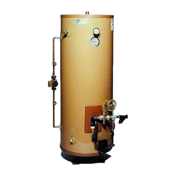
SECTION I - GENERAL DESCRIPTION AND CONSTRUCTION GENERAL DESCRIPTION This book describes a packaged steam powered water heater that is a stationary, self-contained unit. The complete assembly on a standard unit consists of the storage tank, immersion heating coil, steam drip trap, condensate trap, steam strainer, and an ASME rated combination temperature and pressure safety relief valve. -
Page 5: Installation
Traps Two traps should be utilized in the immediate steam piping system of the water heater. The first trap in the system is a thermostatic drip trap that is designed to collect condensate from the main steam line before entering the control valve. Additionally, a main condensate cast iron float and thermostatic trap should be located in the condensate line after the steam coil. - Page 6 PROTECT PROPERTY AND PERSONNEL FROM HARM WHEN THE VALVE FUNCTIONS. All water heaters have a risk of leakage at some unpredictable time. IT IS THE CUSTOMER'S RESPONSIBILITY TO PROVIDE A CATCH PAN OR OTHER ADEQUATE MEANS, SO THAT THE RESULTANT FLOW OF WATER WILL NOT DAMAGE FURNISHINGS OR PROPERTY.
- Page 7 1. All integral components have been properly sized to meet design conditions. Piping to the unit should not be smaller than the size of pipe connections furnished by Hubbell. 2. Install the heating coil in the mating flange using the rubber boot gasket, nuts, bolts, and inserts as supplied.
-
Page 8: Installation And Operation Of Sterlco
SECTION III – INSTALLATION AND OPERATION OF STERLCO TEMPERATURE CONTROL VALVES WARNING / CAUTION HANDLE GENTLY. Temperature control valves are instruments, not pipe fittings. A dent in the body or a sharp bend in the capillary may prevent them from operating. Do not use pipe wrenches. -
Page 9: Operation
TROUBLESHOOTING If the control does not appear to be holding temperature steady, or if not enough heating or cooling is obtained, first check for external conditions which may prevent the control from operating correctly. Examples are: low or fluctuating steam or water supply pressure; damaged or obstructed valves, traps, strainers or other accessories;... -
Page 10: Scheduled Maintenance And Servicing
5. Set the control valve to the desired temperature. Please see Section III for details on the control valve. There is no temperature indicator on the control valve. Rather, by turning the calibrating screw on the top of the valve clockwise you increase the temperature and by turning it counter-clockwise you lower the temperature. - Page 11 scrapers, care should be taken to insure that the tubes are not damaged. 4. Before it is necessary to apply mechanical means for cleaning, try to clean the unit using the following methods. a. Circulate hot fresh water at a reasonable velocity. b.
- Page 12 SINGLE SAFETY SOLENOID SYSTEM (if installed)
- Page 13 DOUBLE SAFETY SOLENOID SYSTEM (if installed)
-
Page 14: Troubleshooting
SECTION VI – TROUBLESHOOTING (See Section III for troubleshooting of Control Valve.) Symptom Probable Cause Corrective Action / Remedy Gradual loss of Tubes are fouled. Clean tubes per Section III, heating capacity. annual scheduled maintenance. Excess silt in bottom of tank. Drain and flush tank per Section III , annual scheduled maintenance. -
Page 15: Miscelaneous Charts And Formulas
SECTION VII – MISCELLANEOUS CHARTS AND FORMULAS METRIC CONVERSIONS... - Page 16 P.O. BOX 288 STRATFORD, CT 06615-0288 PHONE: (203) 378-2659 FAX: (203) 378-3593 INTERNET: http://www.hubbellheaters.com/...
Need help?
Do you have a question about the PS Series and is the answer not in the manual?
Questions and answers