
Related Manuals for Hubbell D


Summary of Contents for Hubbell D
- Page 1 OPERATING AND MAINTENANCE MANUAL FOR ELECTRIC STAINLESS STEEL HEATER FOR DEIONIZED (DI) WATER ELECTRIC HEATER COMPANY BASE MODEL “ D ”...
-
Page 2: Warning / Caution
If questions regarding installation arise, check your local plumbing and electrical inspectors for proper procedures and codes. If you cannot obtain the required information, contact the company. HUBBELL ELECTRIC HEATER COMPANY P.O. BOX 288 STRATFORD, CT 06615 PHONE: (203) 378-2659... -
Page 3: Table Of Contents
SECTION TITLE GENERAL DESCRIPTION AND CONSTRUCTION INSTALLATION SCHEDULED MAINTENANCE AND OPERATION TROUBLESHOOTING SERVICING AND REPLACEMENT OF PARTS MISCELLANEOUS CHARTS AND FORMULAS TABLE OF CONTENTS PAGE #... -
Page 5: Tank Connections
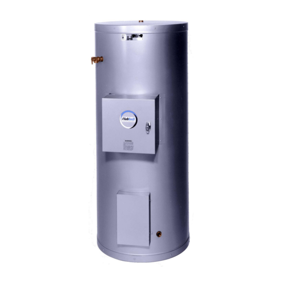
GENERAL DESCRIPTION AND CONSTRUCTION GENERAL DESCRIPTION This booklet describes an electric heater designed specifically for use in deionized (DI) water applications. The complete assembly consists of a type 316L stainless steel storage tank, type 316L stainless steel immersion electric heating element(s), thermostat, safety relief valve, safety high temperature cut out, magnetic contactor(s), and any other required electrical operating control. -
Page 6: Control Thermostat
CONTROL THERMOSTAT The water heater is supplied with a single stage immersion thermostatic switch that is installed and wired at the factory. The thermostat can be adjusted through a range of 100° - 195° F, (an optional low range, 30° - 110°... - Page 7 OUTER SHELL AND INSULATION The tank is encapsulated in 2-inches of high-density fiberglass insulation. The protective shell is constructed of galvaneel and is coated with a durable silver hammertone finish. OPTIONS The following optional features may be included in your water heater. Reference included drawing specific to your heater for further details.
- Page 8 Individually Fused Elements To prevent the possibility of damage to control circuits and other elements in case of electrical overloads, fuses may be supplied for each circuit. Two types of fuses may be used; a type NON for voltages less than 250-volt or type JJS for voltage less than 600-volt. Type JJS Type NON Digital Display...
-
Page 9: Piping Installation
DO NOT TURN ON THE ELECTRIC POWER SUPPLY to this equipment until heater is completely filled with water and all air has been released. If the heater is NOT filled with water when the power is turned on, the heating elements will burn out. For protection against excessive pressures and temperatures, local codes require the installation of a temperature-and-pressure (T&P) relief valve certified by a nationally recognized laboratory that maintains periodic inspection of production of listed equipment of materials, as meeting the... -
Page 10: Electrical Installation
Outlet to floor drain Manual Release Lever Temperature and Pressure Relief Valve 3. Install a relief valve overflow pipe to a nearby floor drain. CAUTION: No valve of any type should be installed between the relief valve and tank or in the drain line. FILLING THE HEATER 1. -
Page 11: Final Checks
THERMOSTAT SETTING (BULB AND CAPILLARY IMMERSION TYPE) The bulb and capillary type thermostat is immersed in a Type 316L stainless steel well in the storage vessel. The full thermostat range is 100-240°F, but should not be operated over 195°F. There is a setting screw, which can be locked at a particular setting to prevent an operator from turning the dial beyond a determined temperature point. -
Page 12: Quarterly Inspection
Visually inspect heating element gasket for evidence of leaks. d. Rub finger around gasket that is between the heating element and tank flange for any evidence of moisture. If moisture is present or a water drip is observed, follow procedure outlined in Section V. -
Page 13: Annual Inspection
Close valve on hot water outlet piping. c. Open valve on drain piping. d. Cold water inlet line pressure will be strong enough to flush sediment from the bottom of the tank out through the drain. Let water run for 3-4 minutes. -
Page 14: Troubleshooting
SECTION IV – Symptom No hot water TROUBLESHOOTING Probable Cause Circuit breaker tripped at source. Blown fuse in transformer, if installed. Circuit breaker at control cabinet tripped, if installed. Blown fuse in element fuse block, if installed. High limit switch tripped. Loose wires. - Page 15 Water temperature below settings at all times Relief valve discharges continuously Faulty thermostat. Heating element not working on all phases Blown fuse in element fuse block, if installed. Heater improperly sized Excessive temperature or pressure in tank Check thermostat adjustment. Monitor thermostat as described in Section III, Quarterly Inspection.
-
Page 16: Vservicing And Replacement Of Parts
SECTION V - Before servicing or replacing any part make sure to turn the power supply switch to the OFF position. SURFACE TEMPERATURE HIGH LIMIT CUT-OFF 1. Disconnect power from unit. 2. Remove access cover. 3. Disconnect the four (4) 14 gauge wires. Control Wires 4. - Page 17 IMMERSION TEMPERATURE HIGH LIMIT CUT-OFF 1. Disconnect power from unit. 2. Remove access cover. 3. Remove high limit cover screw and cover. 4. Disconnect the two (2) 14 gauge wires. 5. Remove capillary tube and bulb from thermowell 6. Remove two (2) mounting screws. 7.
- Page 18 HEATING ELEMENT 1. Disconnect power from unit. 2. Shut off incoming water supply. 3. Attach hose to drain connection. 4. Lift manual release lever on relief valve to let air into system or break union on outgoing water line. 5. Drain water from tank. 6.
-
Page 20: Immersion Thermostat
IMMERSION THERMOSTAT 1. Disconnect power from unit. 2. Remove access cover and locate thermostat. 3. Remove high limit cover screw and cover. 4. Disconnect the two (2) 14 gauge wires. 5. Remove capillary tube and bulb from thermowell. 6. Remove two (2) mounting screws. 7. - Page 21 MAGNETIC CONTACTOR 1. Disconnect power from unit. 2. Disconnect line and load wires to contactor. 3. Disconnect two (2) 14 gauge control circuit wires. 4. Loosen two (2) holding screws and remove contactor. 5. Replace with new contactor using reverse procedure.
-
Page 22: Relief Valve
RELIEF VALVE 1. Disconnect power from unit. 2. Shut off incoming water supply. 3. Lift test lever on relief valve to relieve pressure in tank. 4. Disconnect overflow piping. 5. Unscrew relief valve, remove assembly and replace with new one. 6. -
Page 23: Miscellaneous Charts And Formulas
SECTION VI – ELEMENT CHART Power (kW) Element Part # 208V 240V 480V 50-38683SSN 60-38683SSN 70-38683SSN 80-38683SSN 90-38683SSN 100-38683SSN 15 110-38683SSN 17.3 ---- FORMULAS MISCELLANEOUS CHARTS AND FORMULAS Immersion Length Hairpin 13" 27.9 13" 21.6 13" 17.1 13" 14.4 15" 12.1 ---- 15"... -
Page 24: Torque Values
TORQUE VALUES 18-8 S/S BOLT SIZE IN.-LBS. IN.-LBS. 4-40 4-48 5-40 5-44 6-32 6-40 12.1 8-32 19.8 8-36 22.0 10-24 22.8 10-32 31.7 1/4-20 75.2 1/4-28 94.0 5/16-18 5/16-24 3/8-16 3/8-24 7/16-14 7/16-20 1/2-13 1/2-20 9/16-12 9/16-18 5/8-11 1110 5/8-18 1244 3/4-10 1530...
Need help?
Do you have a question about the D and is the answer not in the manual?
Questions and answers