
Related Manuals for Hubbell EMV


Summary of Contents for Hubbell EMV
- Page 1 OPERATING AND MAINTENANCE MANUAL FOR PACKAGED ELECTRIC TEPID WATER HEATING SYSTEM ELECTRIC HEATER COMPANY BASE MODEL “ EMV ”...
- Page 2 HUBBELL ELECTRIC HEATER COMPANY P.O. BOX 288 STRATFORD, CT 06615 PHONE: (203) 378-2659 FAX: (203) 378-3593 INTERNET: http://www.hubbellheaters.com/ -- IMPORTANT -- Always reference the full model number and serial number when calling the factory. WARNING / CAUTION 1. Tank is to be completely filled with water and all air is to be vented before energizing.
- Page 3 SECTION TITLE PAGE No. GENERAL DESCRIPTION AND CONSTRUCTION INSTALLATION AND START-UP SCHEDULED MAINTENANCE AND OPERATION TROUBLESHOOTING SERVICING AND REPLACEMENT OF PARTS ELEMENT CHARTS...
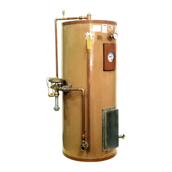
- Page 4 SECTION I - GENERAL DESCRIPTION AND CONSTRUCTION GENERAL DESCRIPTION This manual describes a packaged electric water heater system designed to meet the requirements of ANSI Z358.1-1998 for tepid water delivery to an emergency drench system. The complete assembly consists of the storage tank, immersion electric heating element(s), thermostat(s), safety relief valve, safety high temperature cut out, mixing valve, and any other required electrical operating control.
-
Page 5: Mixing Valve
MIXING VALVE The mixing valve is a triple redundant, thermostatic pressure balanced valve specifically designed emergency safety shower/face/eyewash application. The valve is factory mounted and piped to the water heater. The mixing valve meets OSHA and ANSI requirements and is capable of providing 85°F output regardless of inlet pressure and temperature variations, and the temperature setting is tamper proof and can not be inadvertently adjusted... -
Page 6: Piping Installation
4. On startup, thermal expansion will cause the water to expand. Hubbell recommends that a thermal expansion tank or supplementary pressure relief device be installed in... -
Page 7: Filling The Heater
FILLING THE HEATER 1. Completely close the drain valve. 2. Open the highest tepid water outlet to allow all air to escape from piping. 3. The black plastic knob on the air vent valve must be opened two turns to allow air to escape from the system. -
Page 8: Section Iii - Scheduled Maintenance And Operation
SECTION III - SCHEDULED MAINTENANCE AND OPERATION WARNING / CAUTION Before performing any maintenance procedure, make certain power supply is OFF and cannot accidentally be turned on. MAINTENANCE AND OPERATION The water heater is automatic in its operation. It will maintain a full tank of water at the temperature setting of the thermostat. - Page 9 ANNUAL INSPECTION 1. Flush tank as follows a. Shut off power supply. b. Close valve on hot water outlet piping. c. Open valve on drain piping. d. Cold water inlet line pressure will be strong enough to flush sediment from the bottom of the tank out through the drain.
-
Page 10: Troubleshooting
SECTION IV – TROUBLESHOOTING Symptom Probable Cause Corrective Action / Remedy No hot water in Circuit breaker tripped at Reset circuit breaker. tank source. High limit switch tripped. Reset high limit switch. Loose wires. Torque screws holding wires. Heating element inoperable. Check heating element operation by clamping an Amprobe around each wire to the element. -
Page 11: Servicing & Replacement Of Parts
SECTION V - SERVICING & REPLACEMENT OF PARTS WARNING / CAUTION Before servicing or replacing any part make sure to turn the power supply switch to the OFF position. SURFACE TEMPERATURE HIGH LIMIT CUT-OFF 1. Disconnect power from unit. 2. Remove access cover. 3. - Page 12 Reset Switch 4. Disconnect the two (2) 14 gauge wires. Wires Capillary Tube 5. Remove capillary tube and bulb from thermowell. 6. Remove two (2) mounting screws. Mounting Screws 7. Remove control and install new high limit switch by performing above steps in reverse order.
- Page 13 SINGLE PHASE HEATING ELEMENT 1. Disconnect power from unit. 2. Shut off incoming water supply. 3. Attach hose to drain connection. 4. Lift manual release lever on relief valve to let air into system or break union on outgoing water line. 5.
- Page 14 3-PHASE HEATING ELEMENT 1. Disconnect power from unit. 2. Shut off incoming water supply. 3. Attach hose to drain connection. 4. Lift manual release lever on relief valve to let air into system or break union on outgoing water line. 5.
-
Page 15: Immersion Thermostat
3-PHASE ELEMENT JUMPER CONFIGURATION IMMERSION THERMOSTAT 1. Disconnect power from unit. 2. Remove access cover and locate thermostat. 3. Remove high limit cover screw and cover. Cover Cover Screw... - Page 16 4. Disconnect the two (2) 14 gauge wires. Capillary Tube Wires 5. Remove capillary tube and bulb from thermowell. 6. Remove two (2) mounting screws. Mounting Screws 7. Replace thermostat using reverse procedure. (Note: Be sure to place capillary tube into slot in base prior to installing cover.) MAGNETIC CONTACTOR (3-PHASE ONLY) 1.
-
Page 17: Relief Valve
4. Loosen two (2) holding screws and remove contactor. Mounting Screws (Bottom screw not shown) 5. Replace with new contactor using reverse procedure. RELIEF VALVE 1. Disconnect power from unit. 2. Shut off incoming water supply. 3. Lift test lever on relief valve to relieve pressure in tank. 4. - Page 18 MIXING VALVE 1. Disconnect power from unit. 2. Shut off incoming water supply. 3. Lift test lever on relief valve to relieve pressure in tank. 4. Drain tank. 5. Disconnect unions on both sides of the mixing valve. 6. Remove mixing valve. 7.
-
Page 19: Section Vi - Element Charts
SECTION VI – ELEMENT CHARTS SINGLE PHASE ELEMENT CHART Power (Watts) Element Immersion Resistance Element Part # 120V 208V 240V 277V 480V Length (Ohms) CH-FO-358 ---- 3500 ---- ---- ---- 11 3/8" 12.36 CH-FO-408 ---- 4000 ---- ---- ---- 11 3/8" 10.82 CH-FO-508 ----... - Page 20 P.O. BOX 288 STRATFORD, CT 06615-0288 PHONE: (203) 378-2659 FAX: (203) 378-3593 INTERNET: http://www.hubbellheaters.com/...
Need help?
Do you have a question about the EMV and is the answer not in the manual?
Questions and answers