
Related Manuals for Hubbell MSH


Summary of Contents for Hubbell MSH
- Page 1 OPERATING AND MAINTENANCE MANUAL FOR MARINE ELECTRIC WATER HEATER ELECTRIC HEATER COMPANY BASE MODEL “ MSH and MH ”...
- Page 2 HUBBELL ELECTRIC HEATER COMPANY P.O. BOX 288 STRATFORD, CT 06615 PHONE: (203) 378-2659 FAX: (203) 378-3593 INTERNET: http://www.hubbellheaters.com/ -- IMPORTANT -- Always reference the full model number and serial number when calling the factory. WARNING / CAUTION 1. Tank is to be completely filled with water and all air is to be vented before energizing.
-
Page 3: Table Of Contents
SECTION TITLE PAGE No. GENERAL DESCRIPTION AND CONSTRUCTION INSTALLATION AND START-UP SCHEDULED MAINTENANCE AND OPERATION TROUBLESHOOTING SERVICING AND REPLACEMENT OF PARTS SERVICE PARTS LIST ABS TYPE APPROVAL PROGRAM... -
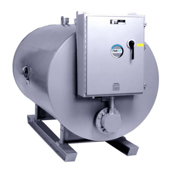
Page 5: General Description And Construction
SECTION I - GENERAL DESCRIPTION AND CONSTRUCTION GENERAL DESCRIPTION This book describes a packaged electric water heater, approved by ABS Americas (A Division of the American Bureau of Shipping) and the USCG (United States Coast Guard), which is a stationary, self contained unit and is designed and constructed specifically for marine applications on board a surface vessel. - Page 6 CONSTRUCTION TANK Standard Tank Construction: The standard storage tank is rated for 100 psi working pressure (150 psi test pressure) and constructed of all welded carbon steel, designed and built in accordance with ASME Section IV and stamped, certified, and registered with the National Board of Boiler and Pressure Vessel Inspectors.
- Page 7 ELECTRICAL ENCLOSURE A louvered control panel available in various sizes and with assorted types of handles is supplied. The standard cabinet is rated NEMA 1, but other NEMA rated enclosures are available, consult drawing for further information. A list of NEMA ratings are available in Section VI.
- Page 8 MAGNETIC CONTACTOR The magnetic contactor(s) is a heavy-duty resistive load type rated for 100,000 cycles. The contactor supplies power to the heating element(s) based on the resistive load (non-inductive) of the heater only when the thermostatic switch is engaged, thereby pulling in the contacts until the desired temperature is reached.
-
Page 9: Installation And Start-Up
Audible Alarm An audible alarm may be installed on the outside of the control panel to give warning of a fault condition. Status Indicating Lamp(s) Optional status indicating lamps may be installed to show when the unit is on, when the heating element is energized, or if there is an alarm condition. - Page 10 4. Do not install in an area where flammable liquids or combustible vapors are present. SECURING OF HEATER 1. The heater is supported by four 2-inch x 2-inch x ¼-inch thick angle iron legs each with a 4-inch x 4-inch x ¼-inch thick steel base pad. Each leg is provided with one 9/16-inch diameter bolt hole for one ½-inch bolt which should be used to secure heater to the deck.
-
Page 11: Scheduled Maintenance And Operation
Outlet to floor drain Install into provided tapping Manual Release Lever Temperature Probe Temperature and Pressure Relief Valve 5. Install a relief valve overflow pipe to a nearby floor drain. CAUTION: No valve of any type should be installed between the relief valve and tank or in the drain line. FILLING THE HEATER 1. - Page 12 This “healing” together with the “wet curing” and expansion of the cement prevents any ongoing corrosion. In the unlikely event a crack greater than 3 mm (1/8”) develops, the cement lining can be easily repaired in the field. For repair procedures please contact Hubbell.
-
Page 13: Troubleshooting
SECTION IV – TROUBLESHOOTING Symptom Probable Cause Corrective Action / Remedy No hot water Circuit breaker tripped at Reset circuit breaker. source. On/Off switch in ‘OFF’ Turn switch to ‘ON’ position. position, if installed. Circuit breaker at control Reset circuit breaker. cabinet tripped, if installed. - Page 14 Water temperature below Faulty thermostat. Check thermostat adjustment. settings at all times Monitor thermostat as described in Section III, Quarterly Inspection. Replace if necessary. Blown fuse in element fuse Replace fuse. block, if installed. Heating element not Check to see that heating working on all phases element is working on all phases, by checking the...
-
Page 15: Vservicing And Replacement Of Parts
SECTION V - SERVICING & REPLACEMENT OF PARTS WARNING / CAUTION Before servicing or replacing any part make sure to turn the power supply switch to the OFF position. MAGNETIC CONTACTOR 1. Disconnect power from unit. 2. Disconnect line and load wires to contactor. 3. - Page 16 4. Disconnect the two (2) 14 gauge wires. Wires Capillary Tube 5. Remove capillary tube and bulb from thermowell 6. Remove two (2) mounting screws. Mounting Screws 7. Remove control and install new high limit switch by performing above steps in reverse order.
- Page 17 8. Withdraw element assembly and remove gasket. Gasket Element Assembly 9. Install new gasket and insert new heating element. 10. Rewire element according to the voltage and phase rating of the unit as shown below. 11. Fill tank and check around gasket for any leaks.
- Page 18 HEATING ELEMENT – STYLE B 1. Disconnect power from unit. 2. Shut off incoming water supply. 3. Attach hose to drain connection. 4. Lift manual release lever on relief valve to let air into system or break union on outgoing water line. 5.
- Page 19 RELIEF VALVE 1. Disconnect power from unit. 2. Shut off incoming water supply. 3. Lift test lever on relief valve to relieve pressure in tank. 4. Disconnect overflow piping. 5. Unscrew relief valve, remove assembly and replace with new one. 6.
-
Page 20: Service Parts List
SECTION VI – MISCELLANEOUS CHARTS AND FORMULAS NEMA ENCLOSURES... - Page 21 ELECTRICAL DATA FORMULAS...
- Page 22 TORQUE VALUES SILICON ALUMINUM 18-8 S/S BRASS 316 S/S MONEL BOLT SIZE BRONZE 2024-T4 IN.-LBS. IN.-LBS. IN.-LBS. IN.-LBS. IN.-LBS. IN.-LBS. 4-40 4-48 5-40 5-44 6-32 10.1 6-40 12.1 11.2 12.7 12.3 8-32 19.8 16.2 18.4 10.8 20.7 20.2 8-36 22.0 18.0 20.4 12.0...
-
Page 23: Abs Type Approval Program
SECTION VII – ABS TYPE APPROVAL PROGRAM... - Page 26 P.O. BOX 288 STRATFORD, CT 06615-0288 PHONE: (203) 378-2659 FAX: (203) 378-3593 INTERNET: http://www.hubbellheaters.com/...
Need help?
Do you have a question about the MSH and is the answer not in the manual?
Questions and answers