
Related Manuals for Hubbell E


Summary of Contents for Hubbell E
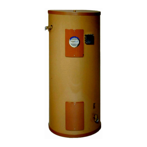
- Page 1 OPERATING AND MAINTENANCE MANUAL FOR COMMERCIAL ELECTRIC WATER HEATER ELECTRIC HEATER COMPANY BASE MODEL “ E ”...
-
Page 2: Warning / Caution
A qualified installer is a person who has licensed training and a working knowledge of the applicable codes regulation, tools, equipment, and methods necessary for safe installation of an electric resistance water heater. If questions regarding installation arise, check your local plumbing and electrical inspectors for proper procedures and codes. -
Page 3: Table Of Contents
SECTION TITLE GENERAL DESCRIPTION AND CONSTRUCTION INSTALLATION SCHEDULED MAINTENANCE AND OPERATION TROUBLESHOOTING SERVICING & REPLACEMENT OF PARTS MISCELLANEOUS CHARTS AND FORMULAS TABLE OF CONTENTS PAGE #... -
Page 5: General Description And Construction
GENERAL DESCRIPTION AND CONSTRUCTION GENERAL DESCRIPTION This book describes a packaged electric water heater that is a stationary, self-contained unit. The complete assembly consists of the storage tank, immersion electric heating element(s), thermostat(s), safety relief valve, safety high temperature cut out, and any other required electrical operating control. -
Page 6: Control Thermostat
CONTROL THERMOSTAT The water heater is supplied as standard with a surface mounted thermostatic switch that is installed and wired at the factory. As an option an immersion thermostat is available. See drawing for specific details. The surface mounted thermostat can be adjusted through a range of 110° - 170° F. The immersion thermostat can be adjusted through a range of 100°... - Page 7 The tank is encapsulated in 2-inch thick polyurethane foam insulation. The insulation is protected by a high impact non-corroding colorized composite protective jacket. OPTIONS The following optional features may be included in your water heater. Reference included drawing specific to your heater for further details. Low Water Cut-Off Used as a safety device, the electronic low water cut-off is used to detect a low water situation and disengage the operating coils in the magnetic contactor(s).
-
Page 8: Piping Installation
If the heater is to be raised off the floor, the entire bottom of the heater should be supported by a solid surface. 2. The water heater should be protected from freezing and waterlines insulated to reduce energy and water waste. -
Page 9: Electrical Installation
Outlet to floor drain Manual Release Lever Temperature and Pressure Relief Valve 4. Install a relief valve overflow pipe to a nearby floor drain. CAUTION: No valve of any type should be installed between the relief valve and tank or in the drain line. FILLING THE HEATER 1. -
Page 10: Quarterly Inspection
MAINTENANCE AND OPERATION The water heater is automatic in its operation. It will maintain a full tank of water at the temperature setting of the thermostat. The water heater should not be turned on without first making sure that the tank is full of water and that all air has been released. -
Page 11: Annual Inspection
Cold water inlet line pressure will be strong enough to flush sediment from the bottom of the tank out through the drain. Let water run for 3-4 minutes. e. Close drain valve. f. Open hot water valve. g. Turn power supply ON. -
Page 12: Troubleshooting
SECTION IV – Symptom No hot water Circuit breaker tripped at source. Reset circuit breaker. High limit switch tripped. Loose wires. Heating element inoperable. Low line voltage. Faulty thermostat. Faulty low water cut-off, if installed. Water temperature Faulty thermostat. below settings at all times Heating element not working on all phases... -
Page 13: Servicing & Replacement Of Parts
SECTION V - Before servicing or replacing any part make sure to turn the power supply switch to the OFF position. SURFACE TEMPERATURE HIGH LIMIT CUT-OFF 1. Disconnect power from unit. 2. Remove access cover. 3. Disconnect the four (4) 14 gauge wires or three (3) 14 gauge wires and a jumper, as required. Control Wires Manual Reset Temperature Controller... - Page 14 IMMERSION TEMPERATURE HIGH LIMIT CUT-OFF 1. Disconnect power from unit. 2. Remove access cover. 3. Remove high limit cover screw and cover. 4. Disconnect the two (2) 14 gauge wires. 5. Remove capillary tube and bulb from thermowell 6. Remove two (2) mounting screws. 7.
-
Page 15: Heating Element
HEATING ELEMENT 1. Disconnect power from unit. 2. Shut off incoming water supply. 3. Attach hose to drain connection. 4. Lift manual release lever on relief valve to let air into system or break union on outgoing water line. 5. Drain water from tank. 6. - Page 16 Single Element Operation 3 Ø Open Delta Wiring for Simultaneous Operation...
- Page 17 Interlocked for Non-Simultaneous Operation Non-Interlocked for Simultaneous Operation...
- Page 18 SURFACE MOUNTED THERMOSTAT 1. Disconnect power from unit. 2. Remove access cover and locate thermostat. 3. Disconnect the two (2) or three (3) 14 gauge wires and jumpers, as required. Control Wires 4. Remove two (2) mounting screws and disconnect from high limit cut-off, if required. Mounting Screws 5.
-
Page 19: Immersion Thermostat
IMMERSION THERMOSTAT 1. Disconnect power from unit. 2. Remove access cover and locate thermostat. 3. Remove high limit cover screw and cover. 4. Disconnect the two (2) or three (3) 14 gauge wires, as required. 5. Remove capillary tube and bulb from thermowell. 6. -
Page 20: Relief Valve
RELIEF VALVE 1. Disconnect power from unit. 2. Shut off incoming water supply. 3. Lift test lever on relief valve to relieve pressure in tank. 4. Disconnect overflow piping. 5. Unscrew relief valve, remove assembly and replace with new one. 6. -
Page 21: Miscellaneous Charts And Formulas
SECTION VI – ELEMENT CHART Element Part # 120V 208V CH-FO-358 ---- CH-FO-408 ---- CH-FO-508 ---- CH-FO-608 2000 CH-FO-304 ---- CH-FO-354 ---- CH-FO-404 ---- CH-FO-454 ---- CH-FO-504 ---- CH-FO-604 1500 TGB-1203-480 ---- TGB-1353-480 ---- TGB-2257L 2500 TGB-1207-240 TGB-1303-480 ---- TGB-1403-480 ---- TGB-2257-240 ----... - Page 22 FORMULAS...
-
Page 23: Torque Values
TORQUE VALUES 18-8 S/S BOLT SIZE IN.-LBS. IN.-LBS. 4-40 4-48 5-40 5-44 6-32 6-40 12.1 8-32 19.8 8-36 22.0 10-24 22.8 10-32 31.7 1/4-20 75.2 1/4-28 94.0 5/16-18 5/16-24 3/8-16 3/8-24 7/16-14 7/16-20 1/2-13 1/2-20 9/16-12 9/16-18 5/8-11 1110 5/8-18 1244 3/4-10 1530...
Need help?
Do you have a question about the E and is the answer not in the manual?
Questions and answers