
Related Manuals for Hubbell BWP Series


Summary of Contents for Hubbell BWP Series
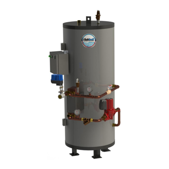
- Page 1 INSTALLATION, OPERATION AND MAINTENANCE MANUAL FOR INDIRECT FIRED WATER HEATER ELECTRIC HEATER COMPANY BASE MODEL “BWP” Edition 2019...
- Page 2 HUBBELL ELECTRIC HEATER COMPANY P.O. BOX 288 STRATFORD, CT 06615 PHONE: (203) 378-2659 FAX: (203) 378-3593 INTERNET: http://www.hubbellheaters.com/ -- IMPORTANT -- Always reference the full model number and serial number when calling the factory. WARNING / CAUTION 1. FLUIDS UNDER PRESSURE MAY CAUSE INJURY WHEN RELEASED.
-
Page 3: Installation
SECTION TITLE PAGE No. GENERAL DESCRIPTION AND CONSTRUCTION General Description General Operation Construction INSTALLATION Codes and Regulations Water Heater Placement Piping Installation Electrical Installation Filling the Heater OPERATION Startup Shutdown SCHEDULED MAINTENANCE AND SERVICING Recommended Maintenance General Maintenance TROUBLESHOOTING MISCELANEOUS CHARTS AND FORMULAS... - Page 4 MODEL BWP - OUTLINE DIMENSIONS...
-
Page 5: General Description And Construction
The BWP model operates using boiler water as its energy source for heating potable hot water. The BWP series can provide potable hot water up to 180°F. Therefore, the supplied boiler water must be within the range of 150°F to a maximum of 220°F and must be at least 5° above the potable water temperature desired from the water heater storage tank outlet. - Page 6 Temperature and Pressure Relief Valve A combination safety temperature and pressure relief valve is installed at the top of every storage tank. An overflow line (either 1-inch or ¾-inch connection) should be utilized from the relief valve outlet to a suitable floor drain. Refer to Section II, Piping Installation, Figure I, Temperature and Pressure Relief Valves section of this manual for additional information.
-
Page 7: Control Panel Components
POTABLE WATER COMPONENTS Thermocouple A thermocouple is mounted in the storage tank. That element is wired to the panel mounted temperature controller for monitoring and control of the desired water temperature. See Control Panel components for additional detail. Temperature and Pressure Safety Relief Valve A temperature and pressure Safety Relief valve is provided for installation in the potable water line downstream of the heat exchanger. -
Page 8: Miscellaneous Components
MISCELLANEOUS COMPONENTS Dial Temperature and Pressure Gauge A combination temperature (70°-250°F) and pressure (0-200 psi) gauge with a 2½-inch dial may be installed within the potable and boiler water inlet and outlet piping for local indication. OPTIONS The following optional features may be included in your water heater. Reference included drawing specific to your heater for further details. -
Page 9: Codes And Regulations
SECTION II INSTALLATION WARNING/CAUTION CODES AND REGULATIONS This equipment must be installed in accordance with all appliance markings, the instructions included in this manual, and any supplemental instructions provided. This equipment must also be in compliance with any installation regulations enforced in the local area where the installation is to be made. -
Page 10: Piping Installation
specified in this manual and/or other applicable appliance markings. 4. Unit should be level to permit proper drainage should any water connections leak. A suitable drain would be capable of accepting hot water discharge (at least 210°F) from the water heater temperature and pressure relief valve. 5. - Page 11 Figure 1: Installation Diagram of an Integrally Mounted Single Pass Heat Exchanger. (Not all components shown are supplied by Hubbell) Figure 2: Installation Diagram displaying a multiple 2-Pass Heat Exchanger Assembly. (Not all components shown are supplied by Hubbell)
- Page 12 2. All integral components have been properly sized to meet design conditions. Piping to the unit should not be smaller than the size of pipe connections furnished by Hubbell. Additionally, piping and components connected to the water heater must be rated for potable water, the water temperatures they will experience, and for their application.
- Page 13 cause damage due to over-tightening which can void the warranty on supplied components. 4. It is considered common practice to install shut-off valves and unions in the potable water and boiler water inlet and outlet piping to aid in servicing. Use caution when threading pipe nipples into storage tank and heat exchanger connections to prevent over-tightening or cross-threading.
-
Page 14: Electrical Installation
(requiring a back-flow preventer or a check valve in the cold-water line) the system will require a means to control expansion. Contact Hubbell, a water heater, and/or a plumbing professional to resolve this situation. ELECTRICAL INSTALLATION IMPORTANT: This heater is wired for 120VAC, 1ph, 60Hz service (unless specified otherwise). - Page 15 SECTION III OPERATION STARTUP CAUTION: To avoid pump damage, do not energize the heater or circulating pump until the tank is full of water. CAUTION: To avoid damage to the heat exchanger, gradually introduce boiler water to the heat exchanger. 1.
-
Page 16: Warning / Caution
IMPORTANT: Hubbell cannot control the use of the product provided, the water conditions in which it is used, or the adherence to a regular maintenance schedule, therefore, the warranty on the BWP unit does not cover poor performance, structural failure, or leaking due to an excessive accumulation of scale. - Page 17 Temperature and Pressure Relief Valve Test the temperature and pressure relief valve(s) on the storage tank and the heat exchanger at least once a year. Do this by manually lifting the relief valve lever briefly. If a relief valve does not open and close properly then it must be replaced with a new relief valve of the same type.
-
Page 18: Troubleshooting
SECTION V TROUBLESHOOTING Symptom Probable Cause Corrective Action / Remedy Gradual loss of HX is fouled. Clean HX per separate O&M. heating capacity. Excess silt in bottom of Drain and flush tank per Section IV, tank. annual scheduled maintenance. Strainers clogged. Clean strainers per Section IV, annual scheduled maintenance. - Page 19 SECTION VI MISCELLANEOUS CHARTS AND FORMULAS METRIC CONVERSIONS...
- Page 20 P.O. BOX 288 STRATFORD, CT 06615-0288 PHONE: (203) 378-2659 FAX: (203) 378-3593 INTERNET: http://www.hubbellheaters.com/...
Need help?
Do you have a question about the BWP Series and is the answer not in the manual?
Questions and answers