Table of Contents
Advertisement
Quick Links
Download this manual
See also:
Use and Care Manual
Advertisement
Table of Contents

Related Manuals for Delfield Concepts


Summary of Contents for Delfield Concepts
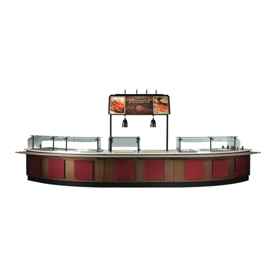
- Page 1 Concepts Serving Systems Installation Manual Please read this manual completely before attempting to install or operate this equipment! Notify carrier of damage! Inspect all components immediately. February 2013...
- Page 2 Operate equipment only on the type of electricity indicated on the specification plate. • Unplug the unit before making any repairs. • Retain this manual for future reference. For customer service, call (800) 733-8829, (800) 773-8821, Fax (989) 773-3210, www.delfield.com...
-
Page 3: Table Of Contents
7. Freight carriers can supply the necessary damage forms upon request. 8. Retain all crating material until an inspection has been made or waived. For customer service, call (800) 733-8829, (800) 773-8821, Fax (989) 773-3210, www.delfield.com... -
Page 4: Serial Number Information
• View and download a copy of your warranty. Regulatory Certifications All Models are certified by: National Sanitation Foundation (NSF) Electical models are also certified by: Underwriters Laboratories (UL) Underwriters Laboratories of Canada (ULC) For customer service, call (800) 733-8829, (800) 773-8821, Fax (989) 773-3210, www.delfield.com... -
Page 5: Tools & Supplies Required
10) Silicone sealant; Dow Corning #732 is ideal. 11) Drill motor. 12) Electrical test meter. 13) 5/16 nut driver to remove shipping braces. 14) Adjustable wrench for leg adjustments. For customer service, call (800) 733-8829, (800) 773-8821, Fax (989) 773-3210, www.delfield.com... -
Page 6: Line Up Installation
11. Connect the electrical quick connects in the bases. Photo 3. First view of units placed next to each other 12. Have the top installed. Verify it is secure and level. For customer service, call (800) 733-8829, (800) 773-8821, Fax (989) 773-3210, www.delfield.com... -
Page 7: Line Up Installation
26. Check electrical outlets for proper operation. 27. Function test all equipment. Photo 6. Kick plate shoulder bolt installed in the key hole slot For customer service, call (800) 733-8829, (800) 773-8821, Fax (989) 773-3210, www.delfield.com... -
Page 8: Beverage Counter Installation
17. Beverage counter weight limit is 600 pounds per 48 linear inches. 18. If the beverage counter has a drop in unit, ensure the gasket in visible. If there is no gasket, silicone the seams around the drop in. For customer service, call (800) 733-8829, (800) 773-8821, Fax (989) 773-3210, www.delfield.com... -
Page 9: Tower Module Installation
5. Verify the module is plugged into a receptacle and the Reach-In is plugged into the GFCI receptacle. If lights were provided, turn on the ON/OFF switch on the back of the tower. 6. Slide the Reach-In in place. For customer service, call (800) 733-8829, (800) 773-8821, Fax (989) 773-3210, www.delfield.com... -
Page 10: Fixed Height Signage Installation
6. Secure in place by sliding push pin through bracket and post. Signage post installed in base. 7. If electrical cord is present, plug into the outlet in the base. For customer service, call (800) 733-8829, (800) 773-8821, Fax (989) 773-3210, www.delfield.com... -
Page 11: Signage Lighting Installation
3. To move the light, pull down on the connection box collar and twist 90 degrees. Slide to the desired location and turn back 90 degrees. 4. Turn switch ON. 5. Check for proper operation. Flexible spotlight installation steps. For customer service, call (800) 733-8829, (800) 773-8821, Fax (989) 773-3210, www.delfield.com... -
Page 12: Flexishield® Food Shields Installation
Make sure there are no kinks in the clear vinyl tubing. For customer service, call (800) 733-8829, (800) 773-8821, Fax (989) 773-3210, www.delfield.com... - Page 13 MINIMUM 14 AWG HA–1 HA–1 250C HA–2 HA–2 HA–3 HA–3 HA–4 HA–4 HA–5 HA–5 HA–6 HA–6 HA = HEATER ASSEMBLY HA = HEATER ASSEMBLY Standard Single Phase Optional Three Phase For customer service, call (800) 733-8829, (800) 773-8821, Fax (989) 773-3210, www.delfield.com...
-
Page 14: Wiring Diagrams
Wiring Diagram, Self-Contained LiquiTec® Cold Pan Serving Counter CONDENSER FAN ON/OFF SWITCH COMPRESSOR COOLING T'STAT 120V Wiring Diagram, Self-Contained Frost Top Serving Counter CONDENSER FAN ON/OFF SWITCH COMPRESSOR 115V For customer service, call (800) 733-8829, (800) 773-8821, Fax (989) 773-3210, www.delfield.com... - Page 15 Concepts Installation Manual Wiring Diagram, Tower Module Wiring Diagram, Mobile Hand Sink For customer service, call (800) 733-8829, (800) 773-8821, Fax (989) 773-3210, www.delfield.com...
- Page 16 980 S. Isabella Rd., Mt. Pleasant, MI 48858, U.S.A. • (989) 773-7981 or (800) 733-8829 • Fax (989) 773-3210 • www.delfield.com Delfield reserves the right to make changes in design or specifications without prior notice. ©2013 The Delfield Company. All rights reserved. Printed in the U.S.A.
Need help?
Do you have a question about the Concepts and is the answer not in the manual?
Questions and answers