Table of Contents
Advertisement
ASSEMBLY AND INSTALLATION
S.R. SMITH ROGUE2 SLIDES ARE MANUFACTURED FOR INSTALLATION
AND USE ON RESIDENTIAL INGROUND SWIMMING POOLS ONLY. THE
ROGUE2 IS NEVER TO BE INSTALLED AND USED ON ABOVEGROUND
POOLS, ONGROUND POOLS, HOUSEBOATS, BOAT DOCKS, FLOATING
DOCKS OR PLATFORMS OR OTHER BODIES OF WATER SUCH AS
LAKES, PONDS, RIVERS, ETC.
SRS AUSTRALIA, PTY LTD
12 Enterprise St
Richlands QLD 4077
Australia
Phone 07 3812 2283 • Fax 07 3812 1187
www.srsmith.com/au
06-820
ROGUE2
INSTRUCTIONS
S.R. SMITH, LLC
CORPORATE HEADQUARTERS
P.O. Box 400 • 1017 S.W. Berg Parkway
Canby, Oregon 97013
USA
Phone (503) 266 2231 • Fax (503) 266 4334
www.srsmith.com
APR16
Advertisement
Table of Contents

Related Manuals for S.R.Smith ROGUE2


Summary of Contents for S.R.Smith ROGUE2
- Page 1 S.R. SMITH ROGUE2 SLIDES ARE MANUFACTURED FOR INSTALLATION AND USE ON RESIDENTIAL INGROUND SWIMMING POOLS ONLY. THE ROGUE2 IS NEVER TO BE INSTALLED AND USED ON ABOVEGROUND POOLS, ONGROUND POOLS, HOUSEBOATS, BOAT DOCKS, FLOATING DOCKS OR PLATFORMS OR OTHER BODIES OF WATER SUCH AS LAKES, PONDS, RIVERS, ETC.
-
Page 2: Table Of Contents
TABLE OF CONTENTS INTRODUCTION ............................3 INSTALLED ROGUE2 STRUCTURAL & INSTALLATION CHECKLIST ............. 4 MAINTENANCE INSTRUCTIONS ........................ 4 ASSEMBLED ROGUE2 LAYOUT ........................ 5 PARTS LIST ..............................6 ASSEMBLY INSTRUCTIONS ........................8 Tools Required ............................8 Rogue 2 Assembly ........................... 8 SLIDE DECK ANCHOR FLANGE PARTS LIST (SOLD SEPERATELY) ........... -
Page 3: Introduction
DANGER – FAILURE TO FOLLOW THESE WARNINGS, INSTRUCTIONS, AND THE OWNER’S MANUAL MAY RESULT IN SERIOUS INJURY OR DEATH. THE ROGUE2 SLIDE IS DESIGNED AND MANUFACTURED FOR INSTALLATION AND USE ON INGROUND SWIMMING POOLS ONLY. DO NOT INSTALL THIS SLIDE ON ABOVE GROUND POOLS, HOUSEBOATS, BOAT DOCKS, FLOATING DOCKS OR PLATFORMS, OR OTHER BODIES OF WATER SUCH AS LAKES, PONDS, RIVERS, ETC. -
Page 4: Installed Rogue2 Structural & Installation Checklist
Observe the position of the exit of the slide as shown in FIGURE O, FIGURE P, and FIGURE R on pages 19 and 20. MAINTENANCE INSTRUCTIONS When hosing down the deck, hose your Rogue2 to wash away any dust, dirt or other debris, which may have accumulated. Be sure that all connections are secure. Tighten hardware if necessary. -
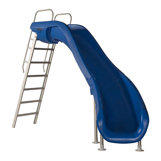
Page 5: Assembled Rogue2 Layout
ASSEMBLED ROGUE2 LAYOUT FIGURE A ROGUE 2 right curve slide shown, left curve is mirror image of right curve. See Appendices for additional slide layout details. -
Page 6: Parts List
PARTS LIST Item Number Description Quantity Garden Hose Adapter (ref. pg 13) 1ea. 1” PVC 90 Elbow ST SCH 40 SXS 1 ea. Plastic Pipe Clamp for 1” SCH 40 6 ea. PVC Ball Valve SCH 80 SXS 1 ea. ¼-20 x 6”... - Page 7 (25) (24)
-
Page 8: Assembly Instructions
13. Loctite® 242 Thread Locking Compound Rogue 2 Assembly Place the slide runway upside down on a surface that will not scratch the slide. (TIP: Use flattened Rogue2 box to help protect slide from scratches during assembly.) FIGURE B 17, 18, ... - Page 9 d. Next, insert the hardware through the holes in the bottom of the runway parts. Insert a (#15) 3.5” Hex Head Screw with a (#17) Flat Washer though each hole as shown in Figure 4. Fasten each screw using a (#17) Flat Washer, (#18) Lock Washer, and (#19) Hex nut.
- Page 10 Carefully turn the slide with the legs and ladder upright for setup. It will be necessary for two people to perform this to avoid damage to the slide. Place the slide at the desired location relative to the pool wall. See MANUFACTURER’S PLACEMENT INSTRUCTIONS on page 19.
- Page 11 Secure the ladder to the slide using the hardware as shown in FIGURE E. Insert a (#16) 3.5” Button Head Screw with a (#17) Flat Washer though each drilled hole. Fasten each screw using a (#17) Flat Washer, (#18) Lock Washer, and (#20) Acorn Nut. With the entrance way secured and the slide in relative final position.
- Page 12 Disassemble each handrail as shown in FIGURE G. Insert the two handrails into the holes on the top of the slide runway rails, and rotate so that the rails are resting in the grooves on the back side of the entrance section. Secure each handrail into the socket using a (#10) Flat Washer, a (#11) Lock Washer, and a (#12) Hex Nut.
- Page 13 For the remaining two ladder spacers, align parts (#7), (#8) and (#9) between the hole in the handrail and the hole in the ladder as in step 12. Use a (#5) 1/4-20 x 6” Carriage Bolt along with a (#10) Flat Washer, a (#11) Lock Washer, and a (#12) Hex Nut to fasten the parts together as shown in FIGURE G and FIGURE H.
-
Page 14: Slide Deck Anchor Flange Parts List (Sold Seperately)
SLIDE DECK ANCHOR FLANGE PARTS LIST (SOLD SEPERATELY) Item Number Part Number Description Quantity 75-209-5000 Aluminum Flange Anchor 4 ea. 05-162 5/16 -18 UNC x 2 3/4 STUD w/ FLAT WASHER & LOCK NUT 16 ea. 05-14-123 1/4-20 UNC x 2 3/4 HHCS 4 ea. -
Page 15: On-Deck Mounting Instructions
ON-DECK MOUNTING INSTRUCTIONS For In-Deck Mounting proceed to Step 19 Bond slide per local codes (see ELECTRICAL BONDING page 18). Place a deck anchor flange over each end of the slide legs. Using the four holes on each flange as a template (see FIGURE I), mark the location of each hole on the deck, Next, drill a 5/16”... -
Page 16: In-Deck Mounting Instructions
IN-DECK MOUNTING INSTRUCTIONS Insert 3/8” (9.5 mm) diameter rebar (not provided) into the holes located at the bottom of each leg making sure that the rebar will be a minimum of three inches (3”) below the deck surface. Bond slide per local codes (see ELECTRICAL BONDING page 16). Secure the ladder so that the ladder steps are level, from side to side, and the ladder is held at 15 degrees (0.26 radians) from vertical. -
Page 17: Slide Plumbing Instructions
SLIDE PLUMBING INSTRUCTIONS FIGURE J Entrance piece hose channel for plumbing Use a drill with a Phillips bit to fasten the (#3) Plastic Pipe Clamp to the ladder as shown below in Figure 12. The hose clamp should be attached with the top of the clamp aligned with the top of the step and the side of the clamp against the ladder side rail, See FIGURE J. -
Page 18: Garden Hose Adaptor Installation Instructions
FIGURE L GARDEN HOSE ADAPTOR INSTALLATION INSTRUCTIONS If connecting the Rogue2 water system to the pool plumbing system is not an option you may connect the water system to a garden hose by following the steps outlined below. Make sure that the Rogue2 water system has been properly assembled as explained in the Rogue2 Installation Instructions. -
Page 19: Manufacturer's Placement Instructions
MANUFACTURER’S PLACEMENT INSTRUCTIONS PROPER ASSEMBLY, INSTALLATION, USE, AND SUPERVISION ARE ESSENTIAL FOR PROPER OPERATION AND TO REDUCE THE RISK OF SERIOUS INJURY. 1. The critical dimensions for placement of the Rogue 2 are as shown in FIGURE O and FIGURE P. A. - Page 20 TABLE 1 Board Minimum Clearance Area Pool Type “C” Dimension “W” Dimension 14’ -6” (4.420 M) 5’ -0” (1.524 M) 14’ -6” (4.420 M) 6’ -0” (1.829 M) 16’ -6” (5.029 M) 6’ -0” (1.829 M) 18’ -6” (5.639 M) 7’...
-
Page 21: Appendices: Rogue2 Slide Footprint
APPENDICES: ROGUE2 SLIDE FOOTPRINT Right curve shown, left curve is mirror image.
Need help?
Do you have a question about the ROGUE2 and is the answer not in the manual?
Questions and answers