
Related Manuals for Burkert 8030 HT


Summary of Contents for Burkert 8030 HT
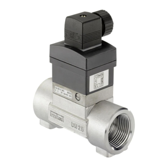
- Page 1 Type 8030 HT - SE30 HT High Temperature Flowmeter with paddle wheel and flow transmitter Operating Instructions Bedienungsanleitung Manuel d'utilisation...
- Page 2 We reserve the right to make technical changes without notice. Technische Änderungen vorbehalten. Sous réserve de modification technique. www.burkert.com © Bürkert SAS, 2013 – 2022 Operating Instructions 2201/03_EU-ML 00449752 / Original EN...
-
Page 3: Table Of Contents
ABOUT THESE OPERATING INSTRUCTIONS ..3 INTENDED USE ............6 BASIC SAFETY INFORMATION ......7 GENERAL INFORMATION ........10 DESCRIPTION ............11 TECHNICAL DATA ..........14 INSTALLATION AND COMMISSIONING ..... 19 MAINTENANCE ............ 33 ACCESSORIES ............ 35 10. PACKAGING, TRANSPORT ......... 36 11. -
Page 4: About These Operating Instructions
ABOUT THESE OPERATING INSTRUCTIONS The Operating Instructions describe the entire life cycle of the device. Please keep the Operating Instructions in a safe place, accessible to all users and any new owners. The Operating Instructions contain important safety information. Failure to comply with these instructions can lead to hazardous situations. - Page 5 Symbols used DANGER Warns against an imminent danger. ▶ Failure to observe this warning can result in death or in serious injury. WARNING Warns against a potentially dangerous situation. ▶ Failure to observe this warning can result in serious injury or even death. CAUTION Warns against a possible risk.
- Page 6 Refers to information contained in these Oper- ating Instructions or in other documents. ▶ Indicates an instruction to be carried out to avoid a danger, a warning or a possible risk. → Indicates a procedure to be carried out. Definition of the word "device" The word "device"...
-
Page 7: Intended Use
Use of the device that does not comply with the instructions could present risks to people, nearby installations and the environment. The 8030 HT flowmeter and the SE30 HT flow trans- mitter are intended exclusively to measure flow rate in liquids. -
Page 8: Basic Safety Information
BASIC SAFETY INFORMATION This safety information does not take into account any contingencies or occurrences that may arise during installation, use and maintenance of the device. The operating company is responsible for the respect of the local safety regulations including for the staff safety. Danger due to high pressure in the installation. - Page 9 Various dangerous situations ▶ Guarantee a set or controlled restarting of the pro- cess, after a power supply interruption. ▶ Use the device only if in perfect working order and in compliance with the instructions provided in the Operating Instructions. ▶...
- Page 10 NOTE The device may be damaged by the fluid in contact with ▶ Systematically check the chemical compatibility of the component materials of the device and the fluids likely to come into contact with them (for example: alcohols, strong or concentrated acids, aldehydes, alkaline compounds, esters, aliphatic compounds, ketones, halogenated aromatics or hydrocarbons, oxidants and chlorinated agents).
-
Page 11: General Information
F-67220 TRIEMBACH-AU-VAL You may also contact your local Bürkert sales office. The addresses of our international sales offices are available on the internet at: country.burkert.com. Warranty conditions The condition governing the legal warranty is the con- forming use of the device in observance of the operating conditions specified in these Operating Instructions. -
Page 12: Description
DESCRIPTION Area of application The 8030 HT flowmeter and the SE30 HT flow transmitter are intended to measure the flow rate of neutral or slightly aggressive liquids free of solid particles. Construction The device is built with an SE30 HT flow transmitter and an S030 HT sensor-fitting incorporating the measuring element. - Page 13 Measuring principle The fluid flowing in the piping makes the paddle-wheel turn. The sensor detects the rotation of the paddle- wheel thus generating a signal which frequency f is proportional to the flow rate Q, acc. to formula: • f = KxQ for a version with 2 pulse outputs, •...
- Page 14 Description of the name plate (example) FLOW : SE30 / 8030 COIL 12-36 V DC OPEN COLLECTOR PNP/NPN S/N 10439 00449694 W41MG 1. Type of flow sensor 2. Measured quantity 3. Type of the device 4. Supply voltage 5. Output data 6.
-
Page 15: Technical Data
TECHNICAL DATA Conditions of use Ambient • Version with pulse outputs: temperature –15 °C...+80 °C (operating) • Version with sinus output: –15 °C...+100 °C Air humidity < 80 %, non condensated IP65, female connector wired, Protection rating acc. to EN 60529 plugged and tightened Conformity to standards and directives The applied standards, which verify conformity with the EU Directives, can be found on the EU Type Exami-... - Page 16 Conformity to the Pressure Equipment Directive → Make sure that the device materials are compatible with the fluid. → Make sure that the pipe DN is adapted for the device. → Observe the fluid nominal pressure (PN) for the device. The nominal pressure (PN) is given by the device manufacturer.
- Page 17 Fluid data Fluid pressure Depends on the fluid temperature: refer to the Operating Instructions of the sensor-fitting used. –15 °C...+125 °C Fluid The fluid temperature may be temperature restricted by the fluid pressure: refer to the Operating Instructions of the sensor-fitting S030 HT. Type and data of refer to the Operating Instructions the fluid...
- Page 18 Materials Part Material Housing PPS, glass fibre reinforced Male fixed connector Female connector type PA / Stainless steel / NBR 2518 / screw / seal Identification label Polyester Sensor-fitting S030 HT Refer to the Operating Instructions of the sensor- fitting used. Electrical data Version with pulse outputs Supply voltage 12...36 V DC, filtered and...
- Page 19 Version with pulse outputs Protection against short circuits NPN and PNP, 700 mA max., frequency up to 250 Hz, duty cycle 1/2 ±10 % NPN output: 0.2...30 V DC PNP output: supply voltage Version with sinus output Supply voltage Without Frequency up to 500 Hz, about 2.8 mV peak-to-peak/ Hz under a 50 kΩ...
-
Page 20: Installation And Commissioning
INSTALLATION AND COMMISSIONING Safety instructions DANGER Risk of injury due to high pressure in the installation. ▶ Stop the circulation of fluid, cut off the pressure and drain the pipe before loosening the process connections. Risk of burning due to high fluid temperatures. ▶... - Page 21 DANGER Risk of injury due to electrical voltage. ▶ If the device is installed either in a wet environment or outdoors, all the electrical voltages must be of max. 35 V DC. ▶ Shut down and isolate the electrical power source before carrying out work on the system. ▶...
- Page 22 WARNING Risk of injury if the fluid pressure/temperature dependency is not respected. ▶ Take account of fluid temperature-pressure depend- ency according to the nature of the materials the fitting is made of (see the technical data and the Operating Instructions of the fitting used). ▶...
- Page 23 NOTE Risk of damage to the device due to the environment ▶ Protect this device against electromagnetic interfer- ence, ultraviolet rays and, when installed outdoors, the effects of the climatic conditions. To make sure the device operates correctly, plug in and tighten the connector. Installation onto the pipe →...
- Page 24 Example: • Specification: - Nominal flow: 10 m - Optimal flow velocity: 2...3 m/s • Solution: intersection between flow rate and flow velocity in the graph gives the appropriate pipe diameter, DN40 (or DN50 for the asterisked fittings). * For the fittings: •...
- Page 25 The names of the following norms have changed in the Operating Instructions: • For the welding ends, norm BS 4825 is renamed BS 4825-1; • For the clamp connections, norm BS 4825 is renamed BS 4825-3. The norm for the clamp connections DIN 32676 series A has been added. English...
- Page 26 Tab. 1: Diagram flow/ rate / fluid velocity/ DN of sensor-fitting S030 HT l/min 1000 3000 2000 DN50 (DN65)* 1000 DN40 (DN50)* DN32 (DN40)* DN25 (DN32)* DN20 (DN25)* DN15 (DN15 or DN20)* DN08 DN06 0.05 0.02 0.05 0.01 0.3 0.5 0.3 0.5 Fluid velocity English...
- Page 27 → Assemble the electronic module and the sensor- fitting according to Fig. 1. Fig. 1: Assembling the SE30 HT and the sensor-fitting S030 HT Wiring DANGER Risk of injury due to electrical discharge ▶ If the device is installed either in a wet environment or outdoors, all the electrical voltages must be of max.
- Page 28 Protect the power supply ▶ Protect the power supply with a correctly rated fuse if it is not protected by default. ▶ Use a shielded cable with an operating tem- perature limit higher than +80 °C. ▶ Use a high quality electrical power supply (filtered and regulated).
- Page 29 Specifications of the connection cables Specification of the cables and the Recommended conductors (not supplied) value Shielded cable Length of the cable Max. 50 m External diameter of the cable 5...8 mm Operating temperature Min. 80 °C Cross section of the local earth Min. 0.75 mm conductor Cross section of the conductors, 0.2...1.5 mm...
- Page 30 Assembling the female connector → Unscrew the pressure screw [1] and remove the pressure ring [2] and the seal [3]. → Remove contact holder [5] from the cover [4]. → Insert the cable into pressure screw [1], through the pressure ring [2], through the seal [3] and finally through the cover [4]. →...
- Page 31 1: V+ (12...36 V DC) 2: NPN pulse output 3: 0 V DC 4: PNP pulse output Fig. 3: Pin assignment of the fixed connector, version with pulse outputs Pulse input on external instrument Terminal block of the 2518 0 V DC Power supply 12-36 V DC Fig. 4: NPN wiring of the version with pulse outputs English...
- Page 32 Pulse input on external instrument 0 V DC Power supply 12-36 V DC Fig. 5: PNP wiring of the version with pulse outputs 1: Not connected 2: Sinus output 3: Sinus output 4: Not connected Fig. 6: Pin assignment of the fixed connector, version with sinus output English...
- Page 33 Terminal block of the 2518 IN = pulse input on remote transmitter Remote transmitter Fig. 7: Wiring of the version with sinus output English...
-
Page 34: Maintenance
MAINTENANCE Safety instructions DANGER Risk of injury due to electrical voltage. ▶ If the device is installed either in a wet environment or outdoors, all the electrical voltages must be of max. 35 V DC. ▶ Shut down and isolate the electrical power source before carrying out work on the system. - Page 35 DANGER Risk of injury due to the nature of the fluid. ▶ Respect the prevailing regulations on accident pre- vention and safety relating to the use of aggressive fluids. WARNING Risk of injury due to non-conforming maintenance. ▶ Maintenance must only be carried out by qualified and skilled staff with the appropriate tools.
-
Page 36: Accessories
ACCESSORIES CAUTION Risk of injury and/or damage caused by the use of unsuitable parts. Incorrect accessories and unsuitable spare parts may cause injuries and damage the device and the sur- rounding area. ▶ Use only original accessories and original spare parts from Bürkert. -
Page 37: Packaging, Transport
10. PACKAGING, TRANSPORT CAUTION Damage due to transport Transport may damage an insufficiently protected device. ▶ Transport the device in shock-resistant packaging and away from humidity and dirt. ▶ Do not expose the device to temperatures that may exceed the admissible storage temperature range. ▶... -
Page 38: Disposal Of The Device
12. DISPOSAL OF THE DEVICE → Dispose of the device and its packaging in an envi- ronmentally-friendly way. NOTE Damage to the environment caused by parts con- taminated by the fluid. ▶ Comply with the national and/or local regulations which concern the area of waste disposal. English...
Need help?
Do you have a question about the 8030 HT and is the answer not in the manual?
Questions and answers