
Subscribe to Our Youtube Channel
Related Manuals for Geokon 4420 Series


Summary of Contents for Geokon 4420 Series
- Page 1 Model 4420 Series Vibrating Wire Crackmeter Instruction Manual ©2020, GEOKON. All rights reserved. Document Revision: W | Release date: 8/4/20...
- Page 3 WARRANTY STATEMENT warrants its products to be free of defects in materials and workmanship, GEOKON under normal use and service for a period of 13 months from date of purchase. If the unit should malfunction, it must be returned to the factory for evaluation, freight prepaid.
-
Page 5: Table Of Contents
TABLE OF CONTENTS 1. INTRODUCTION ............................2. INSTALLATION .............................. 2.1 PRELIMINARY TESTS ........................2.2 CRACKMETER INSTALLATION ....................2.2.1 ANCHORS ............................. 2.2.2 INSTALLATION USING WELDABLE FIXTURES ..............2.2.3 INSTALLATION USING GROUTABLE ANCHORS ..............2.2.4 INSTALLATION USING EXPANSION ANCHORS ..............2.3 SPECIAL INSTALLATION NOTE .................... - Page 6 APPENDIX C. MODEL 4420HT – HIGH TEMPERATURE VERSION ..APPENDIX D. 3D MONITORING ....................D.1 ARRAY OF 3 CRACKMETERS ....................D.2 INSTALLING THE 3D ARRAY ....................D.3 MODEL 4420-3 CANTILEVER 3D ARRAY ALTERNATIVE ......APPENDIX E. MODEL 4420-3 LOW PROFILE CRACKMETER ....
- Page 7 FIGURES FIGURE 1: MODEL 4420 VIBRATING WIRE CRACKMETER ..........1 FIGURE 2: MODEL 4420-3, -12.5, -25 DETAILED VIEW ..........1 FIGURE 3: ANCHOR TYPES WITH DIMENSIONS ............3 FIGURE 4: INSTALLATION USING WELDABLE FIXTURES ..........4 FIGURE 5: INSTALLATION USING GROUTABLE ANCHORS ...........4 FIGURE 6: INSTALLATION USING EXPANSION ANCHORS ...........5 FIGURE 7: TYPICAL COVER PLATE INSTALLATION ............7 FIGURE 8: LIGHTNING PROTECTION SCHEME ...............9 FIGURE 9: GK-404 READOUT ..................10...
- Page 8 TABLES TABLE 1: CRACKMETER ANCHOR SPACING DISTANCES ..........3 TABLE 2: CRACKMETER READING RANGES ..............3 TABLE 3: DIMENSIONS OF EXTENDED RANGE COVERS ..........7 TABLE 4: ENGINEERING UNITS CONVERSION MULTIPLIERS ........13 TABLE 5: THERMAL COEFFICIENT CALCULATION CONSTANTS ......... 15 TABLE 6: MODEL 4420 CRACKMETER SPECIFICATIONS..........
- Page 9 EQUATIONS EQUATION 1: DIGITS CALCULATION ................13 EQUATION 2: DISPLACEMENT CALCULATION.............. 13 EQUATION 3: DISPLACEMENT CHANGE ............... 13 EQUATION 4: THERMALLY-CORRECTED DISPLACEMENT CALCULATION ....14 EQUATION 5: THERMAL COEFFICIENT CALCULATION ..........14 EQUATION 6: 3KΩ THERMISTOR RESISTANCE............. 18 EQUATION 7: MODEL 4420HT 10KΩ THERMISTOR RESISTANCE ......19 EQUATION 8: DISPLACEMENT, CORRECTED FOR TEMPERATURE ......
-
Page 11: Introduction
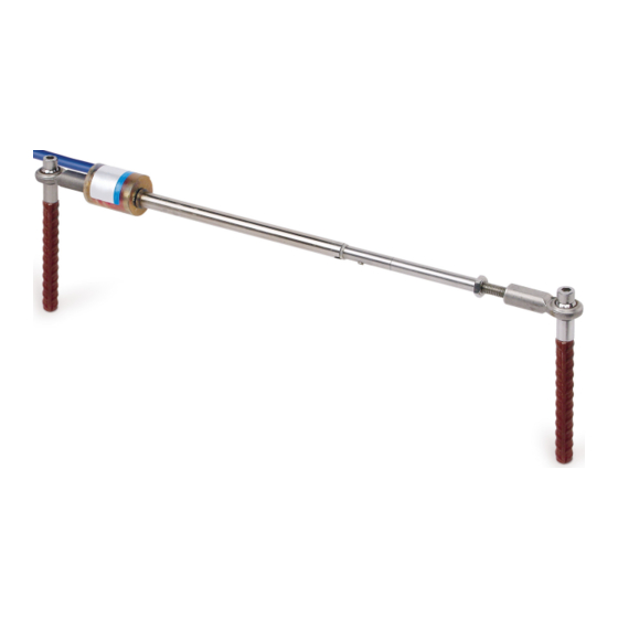
INTRODUCTION Model 4420 vibrating wire crackmeters are designed to measure GEOKON movement across tension cracks in soils, joints in rock and concrete, construction joints in buildings, bridges, pipelines, dams, and more. The instrument consists of a vibrating wire sensing element in series with a heat- treated, stress-relieved spring, which is connected to the wire at one end and to a connecting rod at the other. -
Page 12: Installation
For additional instructions Models 4420HT and 4420-3, see Appendix C and Appendix E respectively. For additional instructions regarding 3D Arrays, see Appendix D. 2.2.1 ANCHORS Three types of anchors are available: ■ Weldable Mounting Fixture ■ Expansion Anchor ■ Groutable Anchor 2 | INSTALLATION | GEOKON... -
Page 13: Figure 3: Anchor Types With Dimensions
The weldable fixture is designed to aid in mounting the crackmeter on steel members. The machine bolt expansion anchors and groutable anchors are used to install the crackmeter on concrete or rock. The anchors are installed at the appropriate spacing distance, depending on the anticipated direction of movement (extension or compression). -
Page 14: Installation Using Weldable Fixtures
Check and record the reading with a portable readout. Use Table 2 or the readings on the calibration sheet to check the position. 2.2.3 INSTALLATION USING GROUTABLE ANCHORS FIGURE 5: Installation using Groutable Anchors INSTALLATION INSTRUCTIONS: Determine the proper setting distance using the spacings listed in Table 1. 4 | INSTALLATION | GEOKON... -
Page 15: Installation Using Expansion Anchors
Using a hammer drill (or other suitable equipment), drill two half-inch diameter holes approximately three inches deep at the proper locations. Shorter holes may be drilled if the anchors are cut down accordingly. Push the cap screws through the swivel bearings and spacers on each end of the crackmeter and then loosely thread them into the groutable anchors. - Page 16 After making an adjustment, align the hole in the swivel bearing over the anchor and check the reading. Make adjustments until the desired reading displays on the readout. Push the cap screw through the swivel bearing and spacer. Tighten into the anchor. Re-tighten the locking nut. 6 | INSTALLATION | GEOKON...
-
Page 17: Instrument Protection
3.1 CABLE SPLICING AND TERMINATION Terminal boxes with sealed cable entries are available from for all types GEOKON of applications. These allow many instruments to be terminated at one location with complete protection of the lead wires. The interior panel of the terminal box can have built-in jacks or a single connection with a rotary position selector switch. -
Page 18: Cable And Connector Protection
SUGGESTED LIGHTNING PROTECTION OPTIONS: ■ Lighting arrestor boards and enclosures are available from . These GEOKON units install where the instrument cable exits the structure being monitored. 8 | INSTRUMENT PROTECTION | GEOKON... -
Page 19: Figure 8: Lightning Protection Scheme
The enclosure has a removable top to allow the customer to service the components or replace the board in the event that the unit is damaged by a lightning strike. A connection is made between the enclosure and earth ground to facilitate the passing of transients away from the instruments. See the figure below. -
Page 20: Taking Readings
The GK-404 will continue to take measurements and display readings until the unit is turned off, either manually or by the Auto-Off timer (if enabled). For more information, consult the GK-404 manual. 10 | TAKING READINGS | GEOKON... -
Page 21: Gk-405 Vibrating Wire Readout
4.2.2 CONNECTING SENSORS WITH BARE LEADS Attach the flying leads to the bare leads of a vibrating wire sensor by GEOKON connecting each of the clips on the leads to the matching colors of the sensor conductors, with blue representing the shield (bare). - Page 22 48.5Ω per km (14.7Ω per 1000') at 20 °C. Multiply these factors by two to account for both directions. Look up the temperature for the measured resistance in Appendix B. For the 4420HT refer to Appendix C. 12 | TAKING READINGS | GEOKON...
-
Page 23: Data Reduction
DATA REDUCTION 5.1 DISPLACEMENT CALCULATION The basic units utilized by for measurement and reduction of data from GEOKON vibrating wire crackmeters are digits. Calculation of digits is based on the following equation: EQUATION 1: Digits Calculation To convert digits to displacement the following equation applies: = (R –... -
Page 24: Temperature Correction
The first step in the temperature correction process is determination of the proper thermal coefficient based on the following equation: K = ((R x M) + B) x G EQUATION 5: Thermal Coefficient Calculation 14 | DATA REDUCTION | GEOKON... -
Page 25: Environmental Factors
Where: is the current reading M is the multiplier, from Table 5 B is the constant, from Table 5 G is the linear gauge factor from the supplied calibration sheet. Model: Multiplier (M): Constant (B): 4420-3 mm (0.125") 0.000520 3.567 4420-12 mm (0.5") 0.000375 1.08... -
Page 26: Troubleshooting
Refer to the expected resistance for the various wire combinations below. Vibrating Wire Sensor Lead Resistance Levels 180Ω (128Ω for Model 4420HT) Red/Black Green/White 3000 at 25 °C Any other wire combination will result in a measurement of infinite resistance. 16 | TROUBLESHOOTING | GEOKON... -
Page 27: Appendix A. Specifications
APPENDIX A. SPECIFICATIONS MODEL 4420 CRACKMETER The table below lists the specifications for all models except for the Model 4420-3 Low Profile Crackmeter. For information on that model, refer to Appendix E. Range: 3 mm/0.125" 12 mm/0.50" 25 mm/1" 50 mm/2" 100 mm/4" 150 mm/6" 200 mm/8" 300 mm/12" Resolution:¹... -
Page 28: Appendix B. Thermistor Temperature Derivation
166.7 58.3 21.89K 2872 582.6 162.0 56.8 20.70K 2750 562.8 157.6 55.6 19.58K 2633 543.7 153.2 18.52K 2523 525.4 149.0 17.53K 2417 507.8 145.0 16.60K 2317 490.9 141.1 TABLE 7: 3KΩ Thermistor Resistance 18 | THERMISTOR TEMPERATURE DERIVATION | GEOKON... -
Page 29: Appendix C. Model 4420Ht - High Temperature Version
APPENDIX C. MODEL 4420HT – HIGH TEMPERATURE VERSION Model 4420HT is a high-temperature crackmeter, rated to 200 °C. This model is supplied with 316 stainless steel U-joints on the ends, as opposed to the rod end bearings installed on standard crackmeters. Due to the U-joint configuration, the overall instrument assembly length is 35 mm (1.375") longer, which you must add when determining anchor spacing distance using in Table 1. -
Page 30: Table 8: Model 4420Ht 10Kω Thermistor Resistance
45.0 8,057 2,316 62 810.6 94 333.2 126 155.1 158 79.5 44.3 7,722 2,235 63 786.6 95 324.8 127 151.7 159 78.0 43.5 TABLE 8: Model 4420HT 10KΩ Thermistor Resistance 20 | MODEL 4420HT – HIGH TEMPERATURE VERSION | GEOKON... -
Page 31: Appendix D. 3D Monitoring
APPENDIX D. 3D MONITORING D.1 ARRAY OF 3 CRACKMETERS Monitoring crack movements in three dimensions requires an array of three 4420 crackmeters, one each for monitoring the X, Y, and Z dimensions. FIGURE 13: Typical 3D Array - Top View FIGURE 14: Typical 3D Array - Front View Range 'A' Length @ Midrange... - Page 32 Using a masonry drill (or other suitable equipment), drill two 3/8 inch (10 mm) diameter holes, 1.25" (32 mm) deep at the proper locations. Insert the expansion anchors into the holes, slotted end down. 22 | 3D MONITORING | GEOKON...
-
Page 33: Model 4420-3 Cantilever 3D Array Alternative
Insert the provided setting tool into the anchor, small end first. Expand the anchor by hitting the large end of the setting tool with several sharp hammer blows. Remove the PVC slotted sleeve or dowel pin securing the transducer shaft. Push the cap screws through the swivel bearings and spacers on each end of the crackmeter and then tighten the cap screws into the anchors. -
Page 34: Figure 16: Cantilever 3D Array, Front View
342.90 mm (13.50") 53.98 mm (2.125") 558.80 mm (22") 34.93 mm (1.375") 28.58 mm (1.125") TABLE 10: 3D Array, Cantilever Version For detailed information about the 4420-3 low profile crackmeter, refer to Appendix E. 24 | 3D MONITORING | GEOKON... -
Page 35: Appendix E. Model 4420-3 Low Profile Crackmeter
MODEL 4420-3 LOW PROFILE CRACKMETER Model 4420-3 low profile vibrating wire crackmeters use a Model 4150 GEOKON strain gauge mounted to the underside of a stainless steel plate, an adjustable oval point set screw, and an instrument cable, which is secured and weatherproofed by a Swagelok connector. -
Page 36: Crackmeter Installation
Slide a washer over the supplied cap screw and tighten it into the expansion anchor. FIGURE 18: Crackmeter assembly using reference disk and two anchors FIGURE 19: Crackmeter assembly with only one anchor and without a reference disk 26 | MODEL 4420-3 LOW PROFILE CRACKMETER | GEOKON... -
Page 37: Specifications
Note: The above zero reading suggestions are given assuming the two sides of the joint are on the same plane when the instrument is installed. If there is a major discrepancy between the two sides, contact geokon to determine if a custom solution is required. -
Page 38: Thermistor
The actual temperature effect of the installed instrument can be arrived at empirically only by simultaneous measurements of deformation and temperature over a short period of time. 28 | MODEL 4420-3 LOW PROFILE CRACKMETER | GEOKON... - Page 40 GEOKON Phone: +1 (603) 448-1562 GEOKON 48 Spencer Street Email: info@geokon.com is an ISO 9001:2015 Lebanon, New Hampshire Website: www.geokon.com registered company 03766, USA...
Need help?
Do you have a question about the 4420 Series and is the answer not in the manual?
Questions and answers