
Subscribe to Our Youtube Channel
Related Manuals for Henny Penny HHC-901


Summary of Contents for Henny Penny HHC-901
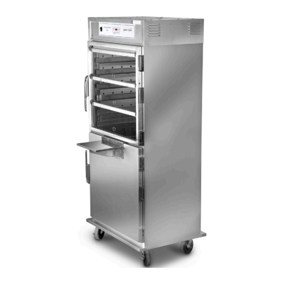
- Page 1 H H e e a a t t e e d d H H o o l l d d i i n n g g C C a a b b i i n n e e t t HHC-901 HHC-904...
- Page 3 Table of Contents Safety......................... iii Chapter 1 Troubleshooting ....................1 1.1 Introduction ......................1 1.2 Testing Instruments ....................1 1.3 Troubleshooting .....................1 1.4 Error Codes ......................3 Chapter 2 Parts ......................5 2.1 Introduction ......................5 2.2 Genuine Parts......................5 2.3 When Ordering Parts....................5 2.4 Prices........................5 2.5 Delivery.........................5 2.6 Warranty .......................5 2.7 Recommended Spare Parts For Distributors ............6 Chapter 3 Wiring Diagrams....................
-
Page 4: Table Of Contents
List of Tables Table 1-1 Troubleshooting....................1 Table 1-2 Error Codes......................3 List of Figures Figure 2-1 Frame and Cover Assembly ................6 Figure 2-2 Control Assembly ....................8 Figure 2-3 Heat Assembly....................9 Figure 2-4 Air and Waterbox Assembly ................10 Figure 3-1 CDT Controls - 120V ..................11 Figure 3-2 Simple Controls - 120V ..................12... - Page 5 S S a a f f e e t t y y The Henny Penny Heated Holding Cabinet has many safety features incorporated. However, the only way to ensure safe operation is to fully understand the proper installation, operation, and maintenance procedures. The instructions in this manual have been prepared to aid you in learning the proper procedures.
-
Page 7: Table 1-1 Troubleshooting
C C h h a a p p t t e e r r 1 1 T T r r o o u u b b l l e e s s h h o o o o t t i i n n g g 1 1 . - Page 8 Problem Cause Correction Transformer Check input and output voltage; replace if defective. defective. Control board Check for 12 volt input from transformer; if control defective. board shows 12 volts, replace control board. O O p p e e r r a a t t i i o o n n A.
-
Page 9: Table 1-2 Error Codes
Problem Cause Correction B. unit will not heat Faulty Check blower and replace if needed. to desired blower. temperature Display not Check probe calibration and change calibration or off- indicating set if necessary. true temperature. One of heat- Check heater and replace as necessary. ers defective. - Page 10 Display Cause Panel Board Correction “E41” Memory Turn unit off, then back on; if “E-41” still shows. have the scrambled. controls initialized; if “E-41” persists, replace control board. “E-50” RAM failure. Turn unit off, then back on; if “E-50” persists, replace con- trol board.
- Page 11 2 2 . . 2 2 G G e e n n u u i i n n e e P P a a r r t t s s Use only genuine Henny Penny parts in your fryer. Using a part of lesser quality or substitute design may result in damage to the unit or personal injury.
-
Page 12: Figure 2-1 Frame And Cover Assembly
2 2 . . 7 7 R R e e c c o o m m m m e e n n d d e e d d S S p p a a r r e e P P a a r r t t s s F F o o r r D D i i s s t t r r i i b b u u t t o o r r s s Recommended replacement parts are indicated with a ✓... - Page 13 Description Qty. Stock Item No. Part No. 81963 DECAL - REAR CONTROL 6CDT 904 77741 ASSY - DOOR RH SS 2B HC901/904 83742 ASSY - DOOR LH SS 2B HC901/904 81927 ASSY - DOOR FLIP LH HC904 79997 ASSY - DOOR FLIP RH HC904 81921 ASSY - DOOR FLIP LH HC901 77742...
-
Page 14: Figure 2-2 Control Assembly
Figure 2-2 Control Assembly Description Qty. Stock Item No. Part No. 79500 DECAL - CONTROL PANEL 13 CDT 901 81960 DECAL - CONTROL PANEL 6 CDT 904 77755 DECAL - CONTROL PANEL - SIMPLE 72277 SWITCH - POWER - SPLASH PROOF 29523 ASSEMBLY - RTD PROBE 30978... -
Page 15: Figure 2-3 Heat Assembly
Description Qty. Stock Item No. Part No. 83759 CONTROL - 90X - 6 CDT SINGLE BOARD ME70-001 BUZZER - PIEZO 16684 COOLING FAN - 115 VOLT 16688 COOLING FAN - 220V Recommend Parts: A = Truck Stock / B = Dist. Stock * = Not Shown Figure 2-3 Heat Assembly Description... -
Page 16: Figure 2-4 Air And Waterbox Assembly
Figure 2-4 Air and Waterbox Assembly Description Qty. Stock Item No. Part No. 77774 ASSY - AIR DUCT - LOWER - 901 77776 ASSY - AIR DUCT - UPPER - 901 80044 ASSY - AIR DUCT - 904 77768 GASKET - DOOR - 901/904 1 PD 71478 WATER BOX ASSEMBLY... -
Page 17: Figure 3-1 Cdt Controls - 120V
C C h h a a p p t t e e r r 3 3 W W i i r r i i n n g g D D i i a a g g r r a a m m s s Figure 3-1 CDT Controls - 120V... -
Page 18: Figure 3-2 Simple Controls - 120V
Figure 3-2 Simple Controls - 120V... - Page 21 blank page...
- Page 22 H H e e n n n n y y P P e e n n n n y y C C o o r r p p o o r r a a t t i i o o n n P P .
Need help?
Do you have a question about the HHC-901 and is the answer not in the manual?
Questions and answers