Table of Contents
Advertisement
Quick Links
EBS Pre-Engineered
Installation, Operation and
Maintenance Instructions
Disclaimer:
This document and the information enclosed within it contain restricted and/or privileged information that are intended only for usage by
authorized Amiad technicians. If you are not a qualified Amiad technician you must not take any action in reliance on this document, unless
permitted by Amiad.
None of the procedures provided in this file may be used in any form or by any means without permission from Amiad.
If you received this file in error, please notify Amiad immediately.
The confidential nature of and/or privilege in the file enclosed is not waived or lost as a result of a mistake or error in this file.
Amiad accepts no liability whatsoever, whether it was caused by:
1. Accessing or other related actions to this file.
2. Any links, procedures or materials provided/attached to this file.
Amiad assumes that all users understand risks involved within this file and/or its attached materials.
All the procedures, drawings, pictures and/or any other information provided in this document are presented as general information only; they
can be altered, removed or changed without any further notice by Amiad.
This document does not replace any certified drawing, procedure or information provided by Amiad in reference to a specific customer, site or
project.
All rights reserved
Amiad USA, Inc.
120 Talbert Road, Suite J
Mooresville, NC 28117
HVAC Filter Skids
Tel: 704.662.3133
E-mail: infousa@amiad.com
Fax: 704.662.3155
Web: www.amiadusa.com
Toll Free: 800.243.4583
Advertisement
Chapters
Table of Contents

Subscribe to Our Youtube Channel
Related Manuals for amiad EBS 769


Summary of Contents for amiad EBS 769
- Page 1 This document and the information enclosed within it contain restricted and/or privileged information that are intended only for usage by authorized Amiad technicians. If you are not a qualified Amiad technician you must not take any action in reliance on this document, unless permitted by Amiad.
-
Page 2: Table Of Contents
Table of Contents General system technical data ........Page 3 Dimensions ..............3 Safety instructions ............4 Description and filter operation ......... 5 Installation ..............6 Commissioning, Start-up and First Operation ...... 7 Maintenance ..............8 Troubleshooting ............10 Disassembling and reassembling ........11 Parts schedule and drawings ........... -
Page 3: General System Technical Data
GENERAL SYSTEM TECHNICAL DATA General System Specifications GPM/Gallons Weight lbs. Flow Surface Reject Pump Screen PUMP Face Flush Flush MODEL Rate EBS Filter Area Voltage Filter Shipping Operation micron Inlet Pipe Line Flow (gpm) Flush 1606 EBS 769 10000 1500 230/460 28.4 4" FLG 8"... -
Page 4: Safety Instructions
INTRODUCTION Amiad filtration equipment has been designed to give long, trouble-free service when properly installed, operated and maintained. This manual contains important installation procedures and should be read prior to installing. This manual is also a guide for proper filter operation, maintenance and winterizing. It is important that maintenance personnel review this manual carefully, including the Safety Precautions and Warnings before performing any maintenance on this filter. -
Page 5: Description And Filter Operation
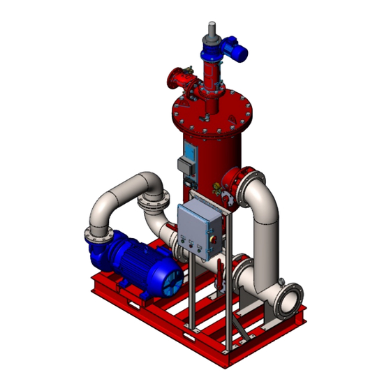
DESCRIPTION OF FILTER OPERATION Filtering process: The EBS series HVAC filter system is a sophisticated yet easy-to-operate automatic filter, with a self-cleaning mechanism driven by an electric motor. The filter system is also equipped with pump, control panel, isolation valves, and check valve all installed on a skid. The EBS filter system is designed to work with various types of screens in filtration degrees from 10 to 500 micron (HVAC STD is 50 micron). -
Page 6: Installation
Stages of cleaning cycle: Under normal operating condition the electrical control panel operates the "EBS" filter in the following manner; 1. The exhaust valve opens to atmosphere. 2. Five seconds delay. 3. The motor starts rotating the suction scanner shaft upward until it reaches the upper limit switch. 4. -
Page 7: Commissioning, Start-Up And First Operation
Electric wiring All electrical works at the installation site must be done by a qualified and authorized electrician only. Make sure that this electrician is fully aware of all the relevant safety instructions. Install the control board in a dry and protected place (In out-door installation sites make sure to use a special control board for out-door installation). -
Page 8: Maintenance
MAINTENANCE Before beginning any maintenance procedure, carefully read the safety instructions chapter of this document and make sure that all the workers at the filtration site are fully aware of and comply with, these and any other local safety instructions. General inspection of the filter operation This is the visual basic general inspection procedure of the filter for proper operation. - Page 9 Maintenance prior to long term cessation of filter operation The following must be done if the filter will not be operated for more than a month. Operate flushing cycle (If possible, with a closed downstream valve). Disconnect the control board from the power and lock the main switch before the limit switch disc reaches the switch.
-
Page 10: Troubleshooting
TROUBLESHOOTING Before beginning any troubleshooting, carefully read the safety instructions chapter of this document and make sure that all the workers at the filtration site are fully aware of and comply with, these and any other local safety instructions. The filtration system may enter a malfunction mode in the following cases: Symptom Remarks and Actions Fault due to... -
Page 11: Equipment
Please note that the screen is heavy and in order to avoid damage and injury it should be lifted only with Amiad’s standard Extractor and a standard lifting device operated by an authorized operator. - Page 12 Fold the Extractor upwards (Figure 1). Figure 1 Insert the Extractor into the screen, about a quarter from top. Make sure that the extractor cushions do not touch the stitch found along the screen interior. Pull the extractor up so that it is firmly set against the inside wall of the Screen (Figure 2) Figure 2: Attach a lifting device to the ring on the Extractor, and extract.
- Page 13 REASSEMBLING THE EBS FILTER Before reassembling, visually check that all components are complete and in good mechanical condition. Before reassembling, carefully read the safety instructions in chapter 2 of this document and make sure that all the workers at the filtration site are fully aware of and comply with, these and any other local safety instructions. Install the seals (6) on the screen (7) and insert the screen into the filter housing (1).
- Page 14 PARTS SCHEDULE Section 1 (1) CAT. No. DESCRIPTION Qty. Material 710105-XXXXXX Housing EBS10K Improved PKPK-3002 ST.37-2 EBS-10 Mega Screen Support Cast-Iron 710105-001639 Cast Iron Amerlock ID-7035 770102-000126 O-Ring Seal (P2-237) Nat 710103-002924 Lower Bearing EBS-40000/EBS-15000 Delrin O-Ring Seal 71x5 (Upper Bearing Disc EBS) NBR 770101-000059 "S"...
- Page 15 SST316L 760103-000109 Spring Washer M6 DIN127 S/ST316 S/ST 316 760103-000094 Flat Washer M6 DIN125S/ST316 SST316 900103-000020 Aluminum Amiad Nameplate, CE, EN Aluminum 760105-000036 Rivet Blind 3x6 DIN7337 S/ST316 S/ST 316 700190-002568 Electrical Junction Box EBS 760101-000531 Phillips Pan Machine Screw M5X16 304...
- Page 16 CAT. No. DESCRIPTION Qty. Material 760102-000084 Hex Nut M5 S/ST304 DIN934 SST304 PD Sub-Assembly Midwest w/o Fitting & Electric 700190-002618 Various Cable 720501-000213 Connector 5/16"x1/8" Brass 770103-000046 Flange Gasket 3" 124X92 NBR PARTS SCHEDULE Section 1 (2) CAT. No. DESCRIPTION Qty.
- Page 17 PARTS DRAWING Section 1 Page 1 Rev: 09.2017 EBS Pre-Engineered Skid IOM...
- Page 18 PARTS DRAWING Section 1 Page 2 Rev: 09.2017 EBS Pre-Engineered Skid IOM...
- Page 19 PARTS DRAWING Section 2 CAT. No. DESCRIPTION Qty. Material 710105-001473 Drive Shaft Housing EBS-10K EPOXY PKPK-3002 ST.37-2 710103-002537 Limit Switch Plate EBS Brass 710103-002540 Drive Shaft (EBS) S/ST303 S/ST 303 710103-002612 Sealing Rope Flange EBS and HD Delrin 770101-000055 O-Ring Seal 38x4 (Sealing Flange EBS) NBR "S" 770101-000053 O-Ring Seal 30x4 (Sealing Flange EBS) NBR "S"...
- Page 20 PARTS DRAWING Section 2 Rev: 09.2017 EBS Pre-Engineered Skid IOM...
- Page 21 PARTS DRAWING Section 3 CAT. No. DESCRIPTION Qty. Material Machined SLN Suction Scanner For Internal Filter - 710103-002976 S/ST.316L EBS 10K 710103-002547 Suction Scanner Shaft EBS 10K S/ST.316L 760105-000043 Pin 10 X 53 S\ST316 S/ST 316 710103-002948 Plug M12 for Mega (19BAR) Delrin 700190-002736 Internal Filter for Scanner EBS 10K/15K...
- Page 22 PARTS SCHEDULE – SKID SYSTEM AND PARTS Pumps and seal kits Description Filter Model Part number Pumps (60 Hz) 25 HP SCOT #57, WEG 256JM SF, BN EBS-10K 769 GPM 720401-000624 30 HP SCOT #59, WEG 286JM SF, BN EBS-10K 883 GPM 720401-000625 30 HP SCOT #59, WEG 286JM SF, BN EBS-10K 1006 GPM...
-
Page 23: Pump Curves
PUMP CURVES Pump Data Sheet - Scot Division of Ardox Corp. Company: Amiad Water Systems Name: EBS_10K_769 Date: 2/5/2016 Pump: Search Criteria: Size: 057-6.9-4.0x3.0 Flow: 769 US gpm Head: 70 ft Type: Endsuct-Encl Speed: 3500 rpm Near miss: 5 % of Head Synch speed: 3600 rpm Dia: 5.75 in... - Page 24 Pump Data Sheet - Scot Division of Ardox Corp. Company: Amiad Water Systems Name: EBS_10K_883 Date: 2/5/2016 Pump: Search Criteria: Size: 059-7.0-6.0x5.0 Flow: 883 US gpm Head: 70 ft Type: Endsuct-Encl Speed: 3500 rpm Near miss: 5 % of Head Synch speed: 3600 rpm Dia: 5.625 in...
- Page 25 Pump Data Sheet - Scot Division of Ardox Corp. Company: Amiad Water Systems Name: EBS_10K_1006 Date: 2/5/2016 Pump: Search Criteria: Size: 059-7.0-6.0x5.0 Flow: 1006 US gpm Head: 70 ft Type: Endsuct-Encl Speed: 3500 rpm Near miss: 5 % of Head Synch speed: 3600 rpm Dia: 5.625 in...
-
Page 26: Level I+ Controller
This document and the information enclosed within it contain restricted and/or privileged information that are intended only for usage by authorized Amiad technicians. If you are not a qualified Amiad technician you must not take any action in reliance on this document, unless permitted by Amiad. - Page 27 Table of Contents 1. Introduction ............................ 2 8 2. Safety .............................. 2 9 2.1 Intended Use .......................... 2 9 2.2 Personnel Selection and Qualification ................ 2 9 2.3 Informal Safety Measures .................... 2 9 2.4 Hazards of Electric Power and Cables ................ 2 9 2.5 Safety Devices .......................... 3 0 3.
-
Page 28: Introduction
Amiad wants to be sure that this equipment meets all of your needs. We depend upon your feedback to make necessary upgrades and improvements. Please contact our office with any comments or questions. -
Page 29: Safety
The operating and maintenance instructions should be kept at the installation site of the Amiad Controller at all times. Applicable local regulations on the prevention of accidents and on the protection of the environment should be posted at the facility. -
Page 30: Safety Devices
It is available in a wide array of power classes and voltages to meet the needs of the market. The initiation of the Amiad filters’ self cleaning systems is by a signal from a differential pressure switch measuring the pressure of the filter inlet and outlet, a timer, control panel pushbutton for manual start or a remote start input. -
Page 31: Transformer
It is used to simplify the operation, thereby making the overall controller more robust. It has a special program designed by Amiad for this filter system. Although the software is available for download by the manufacturer, the program should not be altered without the consent of Amiad to avoid equipment malfunctions. -
Page 32: Transportation
• With the electrical source isolated, connect the appropriate electrical connections to the Amiad Controller. Check on the data plate to ensure the appropriate power supply is connected. • Add necessary short circuit protection as required on schematic. -
Page 33: Deactivation
• Check for leaks within the filter pipes and valves and tighten if necessary as described in the filter O&M. 4.2 Deactivation • Turn disconnect switch to the off position. • Turn all circuit breakers to the off position. • Apply appropriate lock-out/tag-out measures to ensure that power is not accidentally switched on. - Page 34 The adjustable Interval Timer has a small dial for adjusting timing settings in 12 convenient larger ranges, and a larger dial for adjusting through the specific range for both timers. Setting the controller Configuración del controlador Réglage du régulateur Large Dial number Actual Time Número de marcación grande...
-
Page 35: Fault Conditions
6. Fault Conditions There are two different types of faults conditions: 1. A Minor Fault is a condition in which the filter can still continue operating in the current condition, but has a fault that needs to be corrected. The red Reset Fault light will blink during this condition. -
Page 36: Appendix 1 – Pump Iom
Appendix 1 – Pump IOM Rev: 09.2017 EBS Pre-Engineered Skid IOM... - Page 37 INSTALLATION AND MAINTENANCE INSTRUCTIONS FOR ELECTRIC MOTORS Frames 143/5T - 586/7T...
- Page 38 READ CAREFULLY THIS MANUAL BEFORE INSTALLING THE MOTOR. RECEIVING CHECK Check if any damage has occured during transportation. Check nameplate data. Remove shaft locking device (if any) before operating the motor. Turn the shaft with the hand to make sure if it is turning freely. HANDLING AND TRANSPORTATION 1 - General MOTORS MUST NOT BE LIFTED BY THE SHAFT,...
- Page 39 STORAGE If motors are not immediately installed, they must be stored in dry places, free of dust, vibrations, gases, corrosive smokes, under constant temperature and in normal position free from other objects. In case the motors are stored for more than two years, the bearings must be changed or the lubrication grease must be totally replaced after cleaning.
- Page 40 INSTALLATION 1 - Safety All personnel involved with electrical installations, either handling, lifting, operation or maintenance must be well informed and up-to-dated concerning the safety standard and principles that govern the work and carefully follow them. We strongly recommend that these jobs are carried out by qualified personnel.
- Page 41 COMPARE THE CURRENT, VOLTAGE, FREQUENCY, SPEED, OUTPUT AND OTHER VALUES DEMANDED BY THE APPLICATION WITH THE DATA GIVEN ON THE NAMEPLATE. Motors supplied for hazardous locations must installed in areas that comply with that specified on the motor nameplate. KEEP AIR INLET AND OUTLET FREE AND CLEAN. THE AIR BLOWN OUT BY THE MOTOR SHALL NOT ENTER AGAIN.
- Page 42 5 - Balancing WEG MOTORS ARE DYNAMICALLY BALANCED, WITH HALF KEY AT NO LOAD AND UNCOUPLED. Transmission elements such as pulleys, couplings, etc must be dynamically balanced with half key before installation. Use always appropriate tools for installation and removal. 6 - Alignment ALIGN THE SHAFT ENDS AND USE FLEXIBLE COUPLING, WHENEVER POSSIBLE.
- Page 43 7 - Belt Drive When using pulley or belt coupling the following must be observed: Belts must be tighten just enough to avoid slippage when running, according to the specifications stated on the belt supplier recommendation. W W W W W ARNING: ARNING: ARNING: ARNING:...
- Page 44 In case this is not possible, use compatible methods to the motor load and voltage. 3 lead single voltage and 9 lead dual voltage motors can be started as follows: Full Voltage Direct On Line. Auto-Transformer Starting. Electronic Soft-Starting. VFD Starting - subject to verification and application analysis. 6 lead single voltage motors and 12 lead dual voltage motors can be connected as follows: Full Voltage Direct On Line.
- Page 45 When the motor is supplied with protective or monitor temperature device such as thermostats, thermistors, thermal protector, etc, connect their terminals to the corresponding devices on the control panel. 10- Start-Up THE KEY MUST BE FASTENED OR REMOVED BEFORE STARTING THE MOTOR. a) The motor must start and operate smoothly.
- Page 46 LUBRICATION FOLLOW THE REGREASING INTERVALS. THIS IS FUNDAMENTAL FOR PROPER MOTOR OPERATION. 1 - Machines without Grease Nipples Motors up to frame 324/6T are normally fitted without grease nipples. In these cases the regreasing shall be done at the preventive maintenance job observing the following aspects: Disassemble carefully the motors.
- Page 48 WARNING: The table above is specifically intended for relubrication with Polyrex EM grease and bearing absolute operating ® temperature of: C (158 F) for 254/6T to 324/6T frame motors; C (185 F) for 364/5T to 586/7T frame motors. For every 15 C (59 F) above these limits, relubrication interval must be reduced by half.
- Page 49 Compatibility of P Compatibility of P olyrex olyrex EM grease EM grease Compatibility of P Compatibility of P Compatibility of P olyrex olyrex olyrex EM grease EM grease EM grease ® ® ® ® ® with other types of grease: with other types of grease: with other types of grease: with other types of grease:...
- Page 50 and to avoid damages. New bearings shall only be taken out from their cases when assembling them. Before installing a new bearing it is required to check the shaft fitting for any sharp edge or strike signals. For bearing assembly, warm their inner parts with suitable equipment - inductive process - or use suitable tools.
- Page 51 THE INSTALLATION OF HAZARDOUS LOCATION MOTORS MUST BE CARRIED OUT BY SKILLED PEOPLE, AND THE THERMAL PROTECTION MUST BE ALWAYS INSTALLED, EITHER INSIDE OR OUTSIDE THE MOTOR, OPERATING AT THE RATED CURRENT. 2 - Maintenance Maintenance must be carried out by repair shops authorized by WEG.
- Page 52 MOTORS DRIVEN BY VFD Applications using VFD´s without filter can affect motor performance as follows: Lower efficiency. Higher vibration. Higher noise level. Higher rated current. Higher temperature rise. Reduced motor insulation. Reduced bearing life. 1 - Standard Motors Voltages lower than 440V do not require filter. Voltages equal or higher than 440V or lower than 575V require filter for motor power supply cables longer than 20 meters.
- Page 53 WARRANTY TERMS SERIES AND ENGINEERING PRODUCTS WEG warrants its products against defects in workmanship and materials for 18 months from the invoice date issued by the factory, authorized distributor or agent limited to 24 months from manufacturing date independent of installation date as long as the following items are fulfilled accordingly: - Proper transportation, handling and storage;...
Need help?
Do you have a question about the EBS 769 and is the answer not in the manual?
Questions and answers