TECO F510 Quick Start Manual
Hide thumbs
Also See for F510:
- Instruction manual (555 pages) ,
- Quick setting manual (108 pages) ,
- Quick setup manual (2 pages)
Advertisement
Quick Links
Download this manual
See also:
Instruction Manual
Quick Start Guide
This guide is to assist you in installing and running the inverter and verify that it is
functioning correctly for it's main and basic features.
For detailed information and if there are any doubts please refer to the instruction manual.
Step 1
Supply & Motor connection
1) Ensure that the Inverter & the motor have the correct
ratings.
Motor full load amps must not exceed the Inverter rating.
2) Ensure that the supply & Motor cables are connected correctly prior to
power up.
3) Connect supply cable to terminals R/L1, S/L2, T/L3
4) Connect motor cable to terminals U/T1, V/T2, W/T3
(Swap two leads if motor runs in reverse direction).
5) Connect supply Earth and the motor Earth to the drive Earth
terminal.
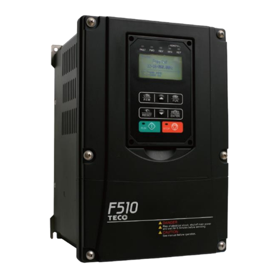
TECO F510 Inverter
Page 1 of 11
KW power and voltage
Note:-
I ) For detailed installation
and wiring refer to the
Instruction
06/10/17
manual.
Advertisement

Related Manuals for TECO F510


Summary of Contents for TECO F510
-
Page 1: Quick Start Guide
TECO F510 Inverter Quick Start Guide This guide is to assist you in installing and running the inverter and verify that it is functioning correctly for it’s main and basic features. For detailed information and if there are any doubts please refer to the instruction manual. - Page 2 Step 2 Apply power to the drive Apply power to the drive, the display will briefly show the supply voltage 440V followed by flashing. 005.00 This is the default (factory set) frequency. If the unit has been used previously then it will show the last frequency programmed.
- Page 3 Remote speed reference and Remote run Step 1 Remote mode wiring. Speed reference. 1) Ensure that you have carried out installation & wiring requirements as per step1 quick start guide on previous page before you proceed. Two analogue inputs are available. AI1 & AI2 Ensure 00-07 = 0 ( Default= Main frequency source).
- Page 4 Step 2 Remote mode Run 1) Remote Run signal can be either a PNP or NPN input type. Set PNP or NPN selection as required by SW3. Note : PNP (positive voltage switching) selection is recommended for use in EU. 2) Connect remote start switch if required according to diagram in the instruction manual.
- Page 5 How to alter Parameters from keypad 1) To alter parameters:- Press the DSP/FUN key, until the first parameter 00-00 is displayed. </ 2) Then use the arrow keys RESET to select the parameter required then press READ ENTER key to read the preset value. </ 3) Use RESET keys to alter the setting of the parameters...
- Page 6 Type Name Functions Main digital Frequency, parameter, voltage, current, temperature and displays Fault message. FAULT: When the inverter has a warning or fault message, the indicator lights up. FWD: When the inverter is in forward run mode, the indicator lights up. RUN mode: Continuously ON.
- Page 7 (8 keys) ▲ Increments parameter number and preset values. ▼ Decrements parameter number and preset values. Alternates frequency and run command source between LOCAL and REMOTE: REMOTE mode: inverter is controlled per parameter settings through control circuit terminals or communication. LOC/REM LOCAL mode: Inverter is controlled through digital operator.
- Page 8 10: 3 wire initialization(230/460V,60Hz) Note:- For Full Parameter List see the Instruction manual Control Modes & Auto Tune F510 provides three control modes. Select the relevant control mode for the application. Default control mode is V/f. V/f can be used for most applications specifically multi-motor or applications where auto tune is not successful or when a customized v/f pattern may be required.
- Page 9 For Motor parameters in V/f mode, set the name plate data in parameter Group 2. SLV Mode set parameters in parameter Group 17 Motor parameters are automatically set when performing an auto-tune (17-10 = 1). In most case no adjustment is required after performing an auto-tune except when using the inverter in special applications (e.g.
-
Page 10: Wiring Diagram
Group 17 Automatic Tuning Function Group Code Parameter Name Range Default Unit 8: Motor acceleration error 9: Warning Rotational Tuning Mode 0: VF Mode 17-14 Selection. 1: Vector Mode V 1.41 Note:- No-load motor voltage 17-08 & (02-19) Parameter determines the rated flux during motor’s rated rotation in SLV control mode. Set the value of this parameter to the same value as parameter 17-08. - Page 11 Braking resistor B1/P R/L1 U/T1 S/L2 V/T2 Main circuit power T/L3 W/T3 Grounding resistance should lower than 100Ω Forward rotation/stop Analog output 1 Reverse rotation/stop Analog signal output 1, 2 Analog output 2 (DC 0~10V)/4-20mA UP command Source(PNP) DOWN command Sink(NPN), Default setting Option Card (JN5-IO-8DO) Multi-step speed...
Need help?
Do you have a question about the F510 and is the answer not in the manual?
Questions and answers