TECO A510s Instruction Manual
A510s series
Hide thumbs
Also See for A510s:
- Instruction manual (674 pages) ,
- Quick setting manual (111 pages) ,
- Manual (107 pages)
Table of Contents
Advertisement
Quick Links
Advertisement
Table of Contents

Related Manuals for TECO A510s


Summary of Contents for TECO A510s
-
Page 2: Table Of Contents
Table of Contents Preface ................................0-1 Chapter 1 Safety Precautions ........................1-1 1.1 Before Supplying Power to the Inverter ....................1-1 1.2 Wiring ................................ 1-2 1.3 Before Operation ............................1-3 1.4 Parameters Setting ........................... 1-3 1.5 Operation ..............................1-4 1.6 Maintenance, Inspection and Replacement ..................... 1-5 1.7 Disposal of the Inverter .......................... -
Page 3: Table Of Contents
3.14 Cable Length vs, Carrier Frequency ..................... 3-36 3.15 Installing an AC Line Reactor ....................... 3-36 3.16 Power Input Wire Size, NFB and MCB Part Numbers ................. 3-37 3.17 Control Circuit Wiring ..........................3-39 3.18 Inverter Specifications .......................... 3-41 3.19 Inverter Derating Based on Carrier Frequency ..................3-48 3.20 Inverter Derating Based on Temperature ..................... -
Page 4: Table Of Contents
4.7.4 Installation & Setting ........................4-354 4.7.5 Descriptions of Terminals, LED and DIP switch ................. 4-356 4.7.6 Parameter setting ........................4-357 4.7.7 Profibus I/O List ........................... 4-357 4.7.8 Error Messages List ........................4-362 4.7.9 GSD File ............................4-362 Chapter 5 Check Motor Rotation and Direction ..................5-1 Chapter 6 Speed Reference Command Configuration ................ -
Page 5: Table Of Contents
Chapter 9 Using PID Control for Constant Flow / Pressure Applications ..........9-1 9.1 What is PID Control ........................... 9-1 9.2 Connect Transducer Feedback Signal ....................9-3 9.3 Engineering Units ............................9-4 9.4 Sleep / Wakeup Function .......................... 9-5 Chapter 10 Troubleshooting and Fault Diagnostics ................10-1 10.1 General .............................. -
Page 6: Preface
The A510S inverter is an electrical / electronic product and must be installed and handled by qualified service personnel. Improper handling may result in incorrect operation, shorter life cycle, or failure of this product as well as the motor. -
Page 7: Chapter 1 Safety Precautions
Chapter 1 Safety Precautions 1.1 Before Supplying Power to the Inverter Warning The main circuit must be correctly wired. For single phase supply use input terminals (R/L1, T/L3) and for three phase supply use input terminals (R/L1, S/L2, T/L3). Terminals U/T1, V/T2, W/T3 must only be used to connect the motor. -
Page 8: Wiring
1.2 Wiring Warning Always turn OFF the power supply before attempting inverter installation and wiring of the user terminals. Wiring must be performed by a qualified personnel / certified electrician. Make sure the inverter is properly grounded. (200V Class: Grounding impedance shall be less than 100Ω. -
Page 9: Before Operation
1.3 Before Operation Warning Make sure the inverter capacity matches the parameters 13-00. Reduce the carrier frequency (parameter 11-01) If the cable from the inverter to the motor is greater than 80 ft (25m). A high-frequency current can be generated by stray capacitance between the cables and result in an overcurrent trip of the inverter, an increase in leakage current, or an inaccurate current readout. -
Page 10: Operation
1.5 Operation Warning Be sure to install all covers before turning on power. Do not remove any of the covers while power to the inverter is on, otherwise electric shock may occur. Do not connect or disconnect the motor during operation. This will cause the inverter to trip and may cause damage to the inverter. -
Page 11: Maintenance, Inspection And Replacement
1.6 Maintenance, Inspection and Replacement Warning Wait a minimum of five minutes after power has been turned OFF before starting an inspection. Also confirm that the charge light is OFF and that the DC bus voltage has dropped below 25Vdc. ... -
Page 12: Chapter 2 Model Description
(2) The A510S inverter has not been damaged during transportation there should be no dents or parts missing. (3) The A510S inverter is the type you ordered. You can check the type and specifications on the main nameplate. (4) Check that the input voltage range meets the input power requirements. -
Page 13: Inverter Models – Motor Power Rating (Hd-Heavy Duty)
2.2 Inverter Models – Motor Power Rating (HD – Heavy Duty) 200V Class Applied Applied Filter Voltage A510S Model Motor Motor with without (KW) (HP) 1ph/3ph, ◎ A510-2001-SH 0.75 200~240V ◎ A510-2002-SH +10%/-15% ◎ A510-2003-SH 50/60Hz ◎ A510-2005-SH3 ◎ A510-2008-SH3 ◎... - Page 14 400V Class Applied Applied Filter Voltage A510S Model Motor Motor with without (KW) (HP) ◎ 0.75 A510-4001-SH3 ◎ A510-4001-SH3F 0.75 ◎ A510-4002-SH3 ◎ A510-4002-SH3F ◎ A510-4003-SH3 ◎ A510-4003-SH3F ◎ A510-4005-SH3 ◎ A510-4005-SH3F ◎ A510-4008-SH3 ◎ A510-4008-SH3F ◎ A510-4010-SH3 ◎ A510-4010-SH3F ◎...
- Page 15 575/690V Class Applied Applied Filter Voltage A510S Model Motor Motor with without (HP) (KW) ◎ A510-5001-SH3 0.75 ◎ A510-5002-SH3 3ph, 575V ◎ A510-5003-SH3 +10%/-15% ◎ A510-5005-SH3 50/60Hz ◎ A510-5008-SH3 ◎ A510-5010-SH3 ◎ A510-6015-SH3 ◎ A510-6020-SH3 ◎ A510-6025-SH3 18.5 ◎ A510-6030-SH3 ◎...
-
Page 16: Chapter 3 Environment And Installation
Chapter 3 Environment and Installation 3.1 Environment The environment will directly affect the proper operation and the life span of the inverter. To ensure that the inverter will give maximum service life, please comply with the following environmental conditions: Protection Protection Class IP20/NEMA 1 or IP00 Ambient Temperature: (-10°C - +40°C (14 -104 °F) -
Page 17: Installation
Air Flow 150mm 150mm Fig 3.2.1: A510S Installation space X = 1.18” (30mm) for inverter ratings up to 25HP X = 1.96” (50mm) for inverter ratings 30HP or higher Important Note: The inverter heatsink temperature can reach up to 194°F / 90°C during operation; make sure to... -
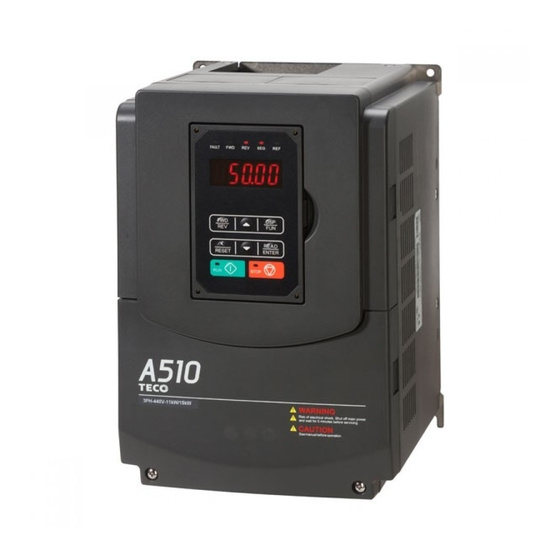
Page 18: External View
3.3 External View (a) 200V 1 ~ 7.5 HP / 400V 1 ~ 7.5 HP / 575V 1~ 3 HP Fan Cover Anti-dust Cover Mounting Hole Rings (4 rings) Front Cover Digital Operator Nameplate and Barcode Terminal Cover (Wall-mounted type, IEC IP20) (Wall-mounted type, IEC IP20, NEMA1) (b) 200V 10 ~ 25 HP / 400V 10 ~ 30 HP / 575V 5~10HP / 690V 15~40HP (Wall-mounted type, IEC IP20) - Page 19 (c) 200V 30 ~ 40 HP / 400V 40 ~ 75 HP / 690V 50~75HP Mounting Hole Front Cover Rings (4 rings) Digital Operator Nameplate and Barcode Terminal Cover (Wall-mounted type, IEC IP20, NEMA1) (d) 200V 50 ~ 100 HP / 400V 100 ~ 215 HP / 690V 100~270HP Anti-dust Cover Mounting Hole Mounting Hole...
-
Page 20: Warning Labels
(e) 200V 125 ~ 150 HP / 400V 270 ~ 425 HP Anti-dust Cover Mounting Hole Mounting Hole Front Cover Rings (4 rings) Rings (4 rings) Front Cover Digital Operator Nameplate Nameplate Digital Operator Terminal Cover and Barcode and Barcode Terminal Cover Wiring Box (Wall-mounted type, IEC IP00) -
Page 21: Removing The Front Cover And Keypad
3.5 Removing the Front Cover and Keypad Caution Before making any wiring connections to the inverter the front cover needs to be removed. It is not required to remove the digital operator before making any wiring connections. 575V/690V 1 –... - Page 22 Step 3: Make wire connections and place cover back Step 4: Fasten screw (b) 200V: 10 ~ 25 HP / 400V: 10 ~ 30 HP /575V: 5~10HP/690V 15~40HP Step 1: Unscrew cover Step 2: Remove cover...
- Page 23 Step 3: Make wire connections and place cover back Step 4: Fasten screw (c) 200V: 30 ~ 40 HP / 400V: 40 ~ 75 HP /690V: 50~75HP (Chassis Type) Step 1: Unscrew cover Step 2: Remove cover...
- Page 24 Step 3: Make wire connections and place cover back Step 4: Fasten screw (d) 200V: 50 ~ 100 HP / 400V: 100 ~ 215 HP /690V: 100~270HP (Chassis Type) Step 1: Unscrew cover Step 2: Remove cover...
- Page 25 Step 3: Make wire connections and place cover back Step 4: Fasten screw (e) 200V: 125 ~ 150 HP / 400V: 270 ~ 425 HP (Chassis Type) Step 1: Unscrew cover Step 2: Remove cover 3-10...
- Page 26 Step 3: Make wire connections and place cover back Step 4: Fasten screw 3-11...
-
Page 27: Built-In Filter Type (400V 1 ~60Hp)
3.5.2 Built-in filter type (400V: 1 ~ 60 HP) Step 1: Unscrew cover Step 2: Remove cover Step 3: Unscrew filter section Step 4: Remove filter cover Step 5: Make connections and place filter cover back Step 6: Fasten screw 3-12... -
Page 28: Wire Gauges And Tightening Torque
To comply with UL standards, use UL approved copper wires (rated 75° C) and round crimp terminals (UL Listed products) as shown in table below when connecting to the main circuit terminals. TECO recommends using crimp terminals manufactured by NICHIFU Terminal Industry Co., Ltd and the terminal crimping tool recommended by the manufacturer for crimping terminals and the insulating sleeve. -
Page 29: Wiring Peripheral Power Devices
3.7 Wiring Peripheral Power Devices Caution After power is shut off to the inverter the capacitors will slowly discharge. Do NOT touch the inverter circuit or replace any components until the “CHARGE” indicator is off. Do NOT wire or connect/disconnect internal connectors of the inverter when the inverter is powered up or after power off but the “CHARGE””... - Page 30 200V: 3HP~8HP/ 400V: 5HP~8HP/575V: 1~3HP Disconnect the ground wire of J1. on the control board (C/B). 200V: 10HP/ 400V: 10~20HP/575V: 5~10HP Disconnect the ground wire of isolated metal plate. 3-15...
- Page 31 200V: 15- 25HP/ 400V: 25~30HP/690V: 15~40HP Disconnect the ground wire of isolated metal plate. 200V: 30-40HP/ 400V: 40-75HP/690V: 50~75HP Disconnect the ground wire of isolated metal plate. 3-16...
- Page 32 200V: 50HP/ 400V: 100HP and the above/690V: 100HP Disconnect the ground screw below the C/B and ground studs of isolated metal plate. Caution Refer to the recommended wire size table for the appropriate wire to use. The voltage between the power supply and the input terminals of the inverter may not exceed 2%.
- Page 33 A filter must be installed when there are inductive loads affecting the A510 inverter. The inverter meets EN55011 Class A, category C3 when the Inverter TECO special filter is used. See section 11.3 for peripheral devices. Inverter: Ground Output terminals T1, T2, and T3 are connected to U, V, and W terminals of the motor.
-
Page 34: General Wiring Diagram
SOURCE PNP Digital Inputs Multi-Step Speed Ref. 3 Section SINK NPN (DEFAULT) Note 1 Fault Reset Jog Command A510S Option Card (PG) External base block 24V Power terminal for digital signal (source) Factory Default (R1A) Multi-Function 24VG Digital signal common (sink) -
Page 35: User Terminals
3.9 User Terminals (Control Circuit Terminals) 200V: 1 ~ 2 HP, 400V: 1 ~ 3HP 200V: 3 ~ 150 HP, 400V: 5 ~ 425HP, 575V:1~10HP, 690V:15~270HP 3-20... - Page 36 Description of User Terminals Type Terminal Terminal Function Signal Level / Information 2-wire forward/ stop (default) * 1 2-wire reversal/ stop (default) * 1 Multi-speed/ position setting command 1 (default) * 1 Signal Level 24 VDC Multi-speed/ position setting command 2 (photo isolated) Digital (default) * 1...
- Page 37 Type Terminal Terminal Function Signal Level / Information L: from 0.0 to 0.5V H: from 4.0 to 13.2V Max. Frequency: 0 - 32KHz Pulse command input, Built-in pull-up resistance. Pulse input Bandwidth: 32KHz When open collector input is signal used, it is not required to connect resistance.
- Page 38 Caution Maximum output current capacity for terminal 10V is 20mA. Multi-function analog output AO1 and AO2 are used for an analog output meter. Do not use these outputs for feedback control. Control board’s 24V and ±10V are to be used for internal control only, Do not use the internal power-supply to power external devices.
-
Page 39: Power Terminals
3.10 Power Terminals 200V: 1 ~ 25HP 200V: 30 ~ 150HP 400V: 1 ~ 40HP Terminal 400V: 50 ~ 425HP 575V: 1 ~ 10HP 690V: 50 ~ 270HP 690V: 15 ~ 40HP R/L1 S/L2 Input Power Supply (For single phase use terminals R/L1 and S/L2) T/L3 B1/P ... - Page 40 400V: 20HP (Frame 3) Terminal screw size B1/P B2 200V: 15~25HP, 400V: 20 ~ 30HP, 690V: 15~40HP Terminal screw size B1/P B2 400V: 40HP Terminal screw size B1/P B2 200V: 30 ~40HP, 400V: 50 ~ 75HP Terminal screw size 3-25...
- Page 41 690V: 50~75HP ‧ Terminal screw size ‧ T ‧ ‧ M6 ‧ M6 200V: 50~60HP, 400V: 100HP Terminal screw size Power supply 400V 75HP 200V 50-60HP/ 400V 100HP 3-26...
- Page 42 690V: 100~150HP Power supply 690V 100~150HP 400V : 125HP Terminal screw size 3-27...
- Page 43 200V: 75~100HP, 400V: 150~215HP, 690V: 175~270HP Terminal screw size 200V: 125~150HP, 400V: 270~425HP Terminal screw size Notes: For wire gauges and screw torques, please refer to the table in section 3.6. 3-28...
- Page 44 3.11 Input / Output Power Section Block Diagram The following diagrams 1 - 8 show the basic configuration of the power sections for the range of horsepower and input voltages. This is shown for reference only and is not a detailed depiction. 1: 200V: 1 HP / 400V: 1 ~ 2 HP 2: 200V: 2 ~ 25 HP / 400V: 3 ~ 40 HP / 575V:1~10HP / 690V: 15~40HP 3-29...
- Page 45 3: 200V: 30 ~ 40 HP / 400V: 50 ~ 75 HP/ 690V: 50~150HP Control DC /DC Circuit Converter DC /DC Cooling Fan Converter Main Power Section 4: 200V: 50 ~ 60 HP / 400V: 100 ~ 125 HP 3-30...
- Page 46 5: 200V: 75, 100 HP 6: 400V: 150HP, 175HP, 215 HP / 690V: 175~270HP DC Link L1/R Reactor U/T1 L2/S V/T2 W/T3 L3/T Control DC /DC Circuit Converter AC/DC Cooling Fan Main Power Section 3-31...
- Page 47 7: 200V: 125, 150 HP 8: 400V: 270HP, 300HP, 375HP, 425 HP DC Link L1/R Reactor U/T1 L2/S V/T2 W/T3 L3/T Control DC /DC Circuit Converter AC/DC Cooling Fan Main Power Section 3-32...
-
Page 48: Cooling Fan Supply Voltage Selection (400V Class)
(1) 400V: 150HP~215HP (2) 400V:270HP~425HP The inverter input voltage range of the A510s 600V class models ranges from 575 to 690Vac. In these models the cooling fan is directly powered from the power supply. Inverter models A510s-6175~6270equires the user to select the correct jumper position based on the inverter input voltage ("690V"... - Page 49 position according to the input voltage. If the voltage setting is too low, the cooling fan will not provide adequate cooling for the inverter resulting in an over-heat error. If the input voltage is greater than 690Vac, select the “690V” position. (3)690V:175HP~270HP 3-34...
-
Page 50: Inverter Wiring
Always use a ground wire that complies with the local codes and standards for electrical equipment and minimize the length of ground wire. When using more than one inverter, be careful not to loop the ground wire, as shown below in Fig. 3.12.1. A510S A510S A510S... -
Page 51: Input Power And Motor Cable Length
3.13 Input Power and Motor Cable Length The length of the cables between the input power source and /or the motor and inverter can cause a significant phase to phase voltage reduction due to the voltage drop across the cables. The wire size shown in Tables 3.16.1 is based on a maximum voltage drop of 2%. -
Page 52: Power Input Wire Size, Nfb And Mcb Part Numbers
The following table shows the recommended wire size, molded case circuit breakers and magnetic contactors for each of the A510S models. It depends on the application whether or not to install a circuit breaker. The NFB must be installed between the input power supply and the inverter input (R/L1, S/L2, T/L3). - Page 53 *3: Control line is the terminal wire on the control board. *4: The NFB and MCB listed in the table are of TECO product numbers, products with same rated specification of other brands may be used. To reduce electrical noise interference, ensure that a RC surge absorber (R: 10Ω/ 5W, C: 0.1μf/1000VDC) is added to both sides of MCB coil.
-
Page 54: Control Circuit Wiring
Fig. 3.17.2 below. Relay Coil 50 mA max. DO1, DO2 + 48V max. Free-wheeling diode (100V, > 100mA) A510S Fig. 3.17.2 Photo-Coupler Connected to an External Relay 3-39... - Page 55 In Section 3.8 the control boards referenced have a jumper SW3 that can select the digital input to terminals - to be set for SINK or SOURCE. The following Fig. 3.17.3 (a.) – (d.) shows examples for the various SINK / Source interfaces. Sink Configuration +24V Source...
-
Page 56: Inverter Specifications
3.18 Inverter Specifications Basic Specifications 200V class Inverter capacity (HP) Rated output Capacity (KVA) 12.6 17.9 22.9 27.8 Heavy Duty type Rated output current (A) 17.5 H.D. Maximum applicable motor (150%/1min) (KW) (0.75) (1.5) (2.2) (3.7) (5.5) (7.5) (11) (15) (18.5) 13.5 20.1... - Page 57 Basic Specifications 400V class Inverter capacity (HP) Rated output Capacity (KVA) 11.3 13.7 18.3 23.6 29.7 34.3 Heavy Duty type Rated output current (A) 14.8 H.D. Maximum applicable motor (150%/1min) (KW) (0.75) (1.5) (2.2) (3.7) (5.5) (7.5) (11) (15) (18.5) (22) 10.1 12.6...
- Page 58 Inverter capacity (HP) Rated Output capacity (KVA) Heavy Duty type Rated output current (A) H.D. Maximum applicable motor (150%/1min) (KW) (200) (220) (280) (315) Motor rated current (A) Rated Output capacity (KVA) Normal Duty type Rated output current (A) N.D. Maximum applicable motor (120%/1min) (KW)
- Page 59 *2: A510S model is designed to use in heavy duty conditions, the factory setting is the HD (Heavy Duty type) mode. *3: The overload capacity of A510S model HD (Heavy Duty) is 150% / 1min, 200% / 2sec. See the table below for the carrier frequency default setting and range.
- Page 60 The following table shows maximum output frequency for each control mode. Duty Cycle Control mode Other settings Maximum output frequency maximum frequency set to V/F + PG 599Hz 599Hz SLV2 200V 1~10HP, 400V 1~15HP 150Hz 200V 15~25HP, 400V 20HP 110Hz 400V 25~30HP 100Hz 200V 30~150HP, 400V...
-
Page 61: General Specifications
General Specifications LCD keypad with parameter copy function (Optional Seven-segment display * 5 + Operation mode LED keypad) Control mode V/F, V/F+PG, SLV, SV, PMSV, PMSLV, SLV2* with space vector PWM mode Frequency control range 0.1Hz~599.0Hz Frequency accuracy Digital references: ±0.01%(-10 to +40°C) Analog references: ±0.1% (25°C (Temperature change) ±10°C ) - Page 62 Location Indoor (protected from corrosive gases and dust). -10~+40°C (14°F~104°F) (IP20/NEMA1), -10~+50°C (14°F~122°F) (IP00) ) without Ambient temperature de-rating; with de-rating, its maximum operation temperature is 60°C (140°F) Storage temperature -20~+70°C (-4°F~+158°F) Humidity 95%RH or less ( no condensation ) Altitude and vibration Altitude of 1000m (3181ft) or below ;...
-
Page 63: Inverter Derating Based On Carrier Frequency
3.19 Inverter Derating Based on Carrier Frequency 200V Models 1 - 20 HP 25 HP Iout Iout 80% of HD 80% of HD 0 2kHz 8kHz 16kHz 0 2kHz 6kHz 12kHz 30 – 40 HP 50 - 100 HP Iout Iout 80% of HD 80% of HD... - Page 64 400V Models 1 - 30 HP 40 - 50 HP Iout 60% of HD 0 2kHz 8kHz 16kHz 60 – 175 HP 215 HP 270 - 375 HP 425 HP Iout Iout 90% of HD 90% of HD 2kHz 4kHz 5kHz 2kHz 5kHz...
- Page 65 575V 1 - 10 HP 575/690V 15 - 30 HP Iout Iout 80% of HD 80% of HD 8kHz 0 2kHz 8kHz 16kHz 0 2kHz 5kHz 10kHz 575/690V 40 - 60 HP 575/690V 75HP Iout 80% of HD 4kHz 8kHz 0 2kHz 5kHz 10kHz...
-
Page 66: Inverter Derating Based On Temperature
3.20 Inverter Derating Based on Temperature Iout 60% of ND 60% of HD Temperature 40°C 60°C 3-51... -
Page 67: Inverter Dimensions
3.21 Inverter Dimensions (a) 200V: 1 – 7.5HP / 400V: 1 - 7.5HP/ 575V:1-3HP (IP20/NEMA1) Dimensions in mm (inch) Inverter Model Net Weight in kg (lbs) A510-2001-SH (5.12) (8.46) (5.91) (4.65) (7.99) (0.20) (4.9) A510-2002-SH (5.12) (8.46) (5.91 (4.65) (7.99) (0.20) (4.9) A510-2003-SH... - Page 68 200V: 10 - 25HP / 400V: 10 - 30HP / 575V: 5~10HP / 690V: 15~40HP (IP20/NEMA1) Dimensions in mm (inch) Inverter Model Net Weight in kg (lbs) A510-2010-SH3 (8.27) (11.81) (8.46) (7.56) (11.26) (0.06) (13.67) A510-2015-SH3 (10.43) (14.17) (8.86) (9.65) (13.39) (0.06) (22.05)
- Page 69 Dimensions in mm (inch) Inverter Model Net Weight in kg (lbs) A510-6020-SH3 (10.43) (14.17) (8.86) (9.65) (13.39) (0.06) (22.05) A510-6025-SH3 (10.43) (14.17) (8.86) (9.65) (13.39) (0.06) (22.05) A510-6030-SH3 (10.43) (14.17) (8.86) (9.65) (13.39) (0.06) (22.05) A510-6040-SH3 (10.43) (14.17) (8.86) (9.65) (13.39) (0.06) (22.05)
- Page 70 (b) 200V: 30 - 40HP / 400V: 40 - 75HP / 690V 50~75HP (IP20/NEMA1) Dimensions in mm (inch) Inverter Model Net Weight in kg (lbs) 286.5 A510-2030-SH3 (11.29) (20.67) (9.92) (8.66) (19.88) (0.13) (66.14) 286.5 A510-2040-SH3 (11.29) (20.67) (9.92) (8.66) (19.88) (0.13) (66.14)
- Page 71 (c) 200V: 50 - 100HP / 400V: 100 - 215HP / 690V: 100~270HP (IP00) Dimensions in mm (inch) Inverter Model Net Weight in kg (lbs) 46.7 A510-2050-SH3 (13.54) (22.83) (11.81) (9.84) (22.05) (0.06) (102.96) 46.7 A510-2060-SH3 (13.54) (22.83) (11.81) (9.84) (22.05) (0.06) (102.96)
- Page 72 46.7 A510-6125-SH3 (13.54) (22.83) (11.81) (9.84) (22.05) (0.06) (102.96) 46.7 A510-6150-SH3 (13.54) (22.83) (11.81) (9.84) (22.05) (0.06) (102.96) 324.5 A510-6175-SH3 (18.07) (31.10) (12.78) (12.60) (29.92) (0.06) (194.01) 324.5 A510-6215-SH3 (18.07) (31.10) (12.78) (12.60) (29.92) (0.06) (194.01) 324.5 A510-6250-SH3 (18.07) (31.10) (12.78) (12.60) (29.92)
- Page 73 Dimensions in mm (inch) Inverter Model Net Weight in kg (lbs) 348.5 49.7 A510-2050-SH3 (13.72) (29.13) (11.81) (9.84) (22.05) (0.06) (109.57) 348.5 49.7 A510-2060-SH3 (13.72) (29.13) (11.81) (9.84) (22.05) (0.06) (109.57) 463.5 1105 324.5 94.4 A510-2075-SH3 (18.25) (43.50) (12.78) (12.60) (29.92) (0.06) (208.12)
- Page 74 (e) 200V: 125 - 150HP / 400V: 270 - 425HP (IP00) Dimensions in mm (inch) Inverter Model Net Weight in kg (lbs) 1000 A510-2125-SH3 (27.17) (39.37) (16.14) (20.87) (10.43) (37.80) (0.08) (405.65) 1000 A510-2150-SH3 (27.17) (39.37) (16.14) (20.87) (10.43) (37.80) (0.08) (405.65) 1000...
- Page 75 (f) 200V: 125 - 150HP / 400V: 270 - 425HP (IP20/NEMA1) Dimensions in mm (inch) Inverter Model Net Weight in kg (lbs) 1313 A510-2125-SH3 (27.24) (51.69) (16.14) (20.87) (10.43) (37.80) (0.08) (432.11) 1313 A510-2150-SH3 (27.24) (51.69) (16.14) (20.87) (10.43) (37.80) (0.08) (432.11) 1313...
-
Page 76: Dimensions For Models With Built-In Filter
3.22 Dimensions for Models with Built-in Filter (a) 400V: 1 - 7.5HP Dimensions in mm (inch) Inverter Model Net Weight in kg (lbs) A510-4001-SH3F (5.12) (12.05) (5.91) (4.65) (7.99) (8.46) (7.71) A510-4002-SH3F (5.12) (12.05) (5.91) (4.65) (7.99) (8.46) (7.71) A510-4003-SH3F (5.12) (12.05) (5.91) - Page 77 (b) 400V: 10 - 30HP Dimensions in mm (inch) Inverter Model Net Weight in kg (lbs) 416.5 A510-4010-SH3F (8.27) (16.40) (8.46) (7.56) (11.26) (11.81) (0.06) (17.63) 416.5 A510-4015-SH3F (8.27) (16.40) (8.46) (7.56) (11.26) (11.81) (0.06) (17.63) 12.5 A510-4020-SH3F (10.43) (19.69) (8.86) (9.65) (13.39)
- Page 78 (c) 400V: 40 - 60HP Dimensions in mm (inch) Inverter Model Net Weight in kg (lbs) 286.5 32.5 A510-4040-SH3F (11.28) (26.73) (9.92) (8.66) (19.88) (20.67) (0.13) (71.65) 286.5 32.5 A510-4050-SH3F (11.28) (26.73) (9.92) (8.66) (19.88) (20.67 (0.13) (71.65) 286.5 32.5 A510-4060-SH3F (11.28) (26.73)
-
Page 79: Chapter 4 Keypad And Programming Functions
Chapter 4 Keypad and Programming Functions 4.1 LED Keypad 4.1.1 Keypad Display and Keys Reverse Direction External Sequence Forward Direction Status Indicator Indicator Status Indicator External Reference Fault Status Indicator Indicator 5 Digit, 7 Segment LED Display 8 button Membrane Keypad Run Status Indicator Stop Status... - Page 80 KEYS (8) Description RUN Inverter in Local Mode STOP STOP Inverter ▲ Parameter navigation Up, Increase parameter or reference value ▼ Parameter navigation down, decrease parameter or reference value Used to switch between Forward and Reverse direction FWD/REV Used to scroll to next screen DSP/FUN Frequency screen ...
-
Page 81: Seven Segment Display Description
4.1.2 Seven Segment Display Description Actual LED Display Actual LED Display Actual LED Display Actual LED Display ° Display output frequency Frequency Reference Set Frequency Reference LED lights on LED flashes Flashing digit At power-up, the display will show the frequency reference setting and all LEDs are flashing. Press the ... - Page 82 LED Display Examples Seven Segment Display Description 1. Displays the frequency reference at power-up. 2. Displays the actual output frequency during run operation. Displays parameter code. Displays the setting value of parameter. Displays input voltage. Displays inverter current. Displays DC Bus Voltage. Displays temperature.
-
Page 83: Led Indicator Description
4.1.3 LED Indicator Description Fault LED State Description FAULT LED No Fault Active Illuminated Fault Active Forward LED State Description FWD LED Inverter in reverse direction Illuminated Inverter is running in forward direction Flashing Forward direction active, no run command Reverse LED ... - Page 84 SEQ LED State Description SEQ LED Sequence controlled from keypad Illuminated Sequence set from external source REF LED State Description REF LED Frequency reference set from keypad Frequency reference set from external source Illuminated Run / Stop Status Indicators...
-
Page 85: Power-Up Monitor
4.1.4 Power-up Monitor Power-up Changing Monitor at Power-up 12- 00 Display Selection Highest bit -> 0 0 0 0 0 <- Lowest bit The setting range for each bit is 0 ~ 7 from the highest bit to the lowest bit. 0: No display 4: Temperature Range... -
Page 86: Modifying Parameters/ Set Frequency Reference
Example: 12- 00=【12345】 4.1.5 Modifying Parameters/ Set Frequency Reference Example: Modifying Parameters... - Page 87 Example: Set Frequency Reference Inverter stopped: Inverter is running: Display Voltage Class Display Voltage Class Flashing for 3 seconds Flashing for 3 seconds Display Frequency Reference ▲ Display Frequency Reference Press Press RUN 1x Press </RESET Output Frequency Set Frequency Reference Press </RESET Press Set Frequency Reference 0.01 Hz...
-
Page 88: Operation Control
4.1.6 Operation Control Stopped Running Stopping Stopped Output Frequency Indicator Indicator Indicator STOP Indicator STOP STOP STOP STOP STOP STOP STOP STOP 4-10... -
Page 89: Keypad Display And Keys
4.2 LCD Keypad 4.2.1 Keypad Display and Keys Reverse Direction External Sequence Forward Direction Status Indicator Indicator Status Indicator External Reference Fault Status Indicator Indicator LCD Display Monitor Fref Ref 12-16=005.00Hz 12-17=000.00Hz 12-18=0000.0A 8 button Run Status Membrane Keypad Indicator Stop Status Indicator DISPLAY... - Page 90 KEYS (8) Description RUN Inverter in Local Mode STOP STOP Inverter ▲ Parameter navigation Up, Increase parameter or reference value ▼ Parameter navigation down, decrease parameter or reference value FWD/REV Used to switch between Forward and Reverse direction Used to scroll to next screen DSP/FUN Frequency screen ...
-
Page 91: Keypad Menu Structure
4.2.2 Keypad Menu Structure Main Menu The A510S inverter main menu consists of two main groups (modes). The DSP/FUN key is used to switch between the monitor mode and the parameter group mode. Mode Description Monitor Mode View inverter status, signals and fault data. -
Page 92: Monitor Mode
Monitor Mode In monitor mode inverter signals can be monitored such as output frequency, output current and output voltage, etc…) as well as fault information and fault trace. See Fig 4.2.2.2 for keypad navigation. Power ON Group Monitor 00 Basic Func. Freq Ref 12-16=005.00Hz 01 V/F Pattern. -
Page 93: Programming Mode
Programming Mode In programming mode inverter parameters can be read or changed. See Fig 4.2.2.3 for keypad navigation. Fig 4.2.2.3 Programming Mode Notes: - The parameters values can be changed from the Edit screen with the up, down and < / RESET shift key. - To save a parameter press the READ/ENTER key. - Page 94 Auto-tuning Mode In the auto-tuning mode motor parameters can be calculated and set automatically based on the selected control mode. See Fig 4.2.2.4 for keypad navigation. Group 17 Auto-tuning 18 Slip Compen 19 Traverse Func. READ E NT ER Press ▲ or ▼ key to change the value. READ Edit 17-00...
- Page 95 4.2.2 Notes: 1. Use the up and down keys to scroll though the auto-tuning parameter list. Depending on the selected control mode in parameter 00-00, part of auto-tuning parameters will not be accessible. (Refer to the Auto-tuning Group 17 parameters). 2.
-
Page 96: Parameters
4.3 Parameters Parameter group Group Name Basic Parameters Group 00 Group 01 V/F Control Parameters Group 02 IM Motor Parameters Group 03 External Digital Input and Output Parameters Group 04 External Analog Input and Output Parameters Group 05 Multi-Speed Parameters Automatic Program Operation Parameters Group 06 Group 07... - Page 97 Group 00: Basic Parameters Control mode Code Parameter Name Setting Range Default Unit Attribute SLV SV SLV2 0: V/F 1: V/F+PG 2: SLV Control Mode 00-00 3: SV Selection 4: PMSV 5: PMSLV 6: SLV2 0: Forward Motor’s Rotation 00-01 1: Reverse Direction 0: Keypad...
- Page 98 Group 00: Basic Parameters Control mode Code Parameter Name Setting Range Default Unit Attribute SLV SV SLV2 5: Reserved 6: Reserved 7: AI2 Auxiliary Frequency Main and 0: Main Frequency Alternative 00-07 1: Main frequency + Frequency Command Modes Alternative Frequency Communication Frequency 0.00~599.00...
- Page 99 Group 00: Basic Parameters Control mode Code Parameter Name Setting Range Default Unit Attribute SLV SV SLV2 Acc/Dec Time 1 and Time 4 Emergency Stop 0.1~6000.0 00-26 Time 0: HD (Heavy Duty HD/ND Mode Mode) 00-27 Selection *** 1: ND (Normal Duty Mode) 0: Positive Characteristic (0~10V/4~20mA is...
- Page 100 Group 00: Basic Parameters Control mode Code Parameter Name Setting Range Default Unit Attribute SLV SV SLV2 00-47 User parameter 6 00-47 00-48 User parameter 7 00-48 00-49 User parameter 8 00-49 00-50 User parameter 9 00-50 00-51 User parameter 10 00-51 Set 13-06 = 1, start user 00-52 User parameter 11...
- Page 101 Group 01: V/F Control Parameters Control mode Code Parameter Name Setting Range Default Unit Attribute SLV SV SLV2 Middle Output Frequency 2 of 01-04 0.0~599.0 Motor 1 200V: 0.0~255.0 Middle Output 400V: 0.0~510.0 Voltage 2 of 01-05 575V: 0.0~670.0 Motor 1 690V: 0.0~804.0 Middle Output Frequency 1 of...
- Page 102 Group 01: V/F Control Parameters Control mode Code Parameter Name Setting Range Default Unit Attribute SLV SV SLV2 690V: 648.0~804.0 690.0 Torque Compensation 01-15 1~10000 Time Maximum Output Frequency of 01-16 5.0~599.0 60.0 Motor 2 200V: 0.1~255.0 220.0 Maximum Output 400V: 0.2~510.0 440.0 Voltage of Motor...
- Page 103 Group 02: IM Motor Parameters Control mode Code Parameter Name Setting Range Default Unit Attribute SLV SV SLV2 No-Load Current 02-00 0.01~600.00 of Motor1 Modes of V/F, V/F+PG are 10%~200% of Rated Current of inverter’s rated current. 02-01 Motor1 Modes of SLV, SV are 25%~200% of inverter’s rated current.
- Page 104 Group 02: IM Motor Parameters Control mode Code Parameter Name Setting Range Default Unit Attribute SLV SV SLV2 690V: 504~720 No-Load Current 02-20 0.01~600.00 of Motor 2 Rated Current of 10%~200% of inverter’s 02-21 Motor 2 rated current Rated Rotation 02-22 0~60000 Speed of Motor 2...
- Page 105 Group 03: External Digital Input and Output Parameters Control mode Code Parameter Name Setting Range Default Unit SLV SV SLV2 Attribute 0: 2-Wire Sequence (ON: Forward Run Multi-Function Command). Terminal 1: 2-Wire Sequence 03-00 (ON: Reverse Run Function Command). Setting-S1 2: Multi-Speed/Position Setting Command 1 3: Multi-Speed/Position...
- Page 106 Group 03: External Digital Input and Output Parameters Control mode Code Parameter Name Setting Range Default Unit SLV SV SLV2 Attribute 26: 3-Wire Sequence (Forward/Reverse command). 27: Local/ Remote Selection 28: Remote Mode Selection 29: Jog Frequency Selection 30: Acceleration/ Deceleration Time Selection 2 31: Inverter Overheating...
- Page 107 Group 03: External Digital Input and Output Parameters Control mode Code Parameter Name Setting Range Default Unit SLV SV SLV2 Attribute Mode (Stop Command) 54: Reserved 55: Reserved 56: Reserved 57: Reserved 58: Safety Function 59: Reserved 60: Reserved 61: Reserved 62: EPS Function (S1~S8) DI Scan 0: Scan Time 4ms...
- Page 108 Group 03: External Digital Input and Output Parameters Control mode Code Parameter Name Setting Range Default Unit SLV SV SLV2 Attribute 14: Mechanical Braking Control (03-17~18) 15: Reserved 16: Reserved 17: Reserved 18: PLC status 19: PLC Control Contact 20: Zero Speed 21: Inverter Ready 22: Under Voltage Detection...
- Page 109 Group 03: External Digital Input and Output Parameters Control mode Code Parameter Name Setting Range Default Unit SLV SV SLV2 Attribute 44: Reserved 45: PID sleep 46: Reserved 47: Reserved 48: Reserved 49: Reserved 50: Frequency Detection 3 (> 03-44+03-45) 51: Frequency Detection 4 (<...
- Page 110 Group 03: External Digital Input and Output Parameters Control mode Code Parameter Name Setting Range Default Unit SLV SV SLV2 Attribute from last set frequency when stopped 3: Refresh frequency at acceleration. Range and definition are Photo-coupler the same as those of 03-28 Output 03-11, 03-12...
- Page 111 Group 03: External Digital Input and Output Parameters Control mode Code Parameter Name Setting Range Default Unit SLV SV SLV2 Attribute Selection Deceleration Time 2 Frequency 03-44 0.0~599.0 Detection Level 2 Frequency 03-45 0.1~25.5 Detection Width 2 Frequency 03-46 0.0~599.0 Detection Level 3 Frequency 03-47...
- Page 112 Group 04: External Analog Input and Output Parameters Control mode Code Parameter Name Setting Range Default Unit Attribute SLV SV SLV2 8: Frequency Lower Limit 9: Jump Frequency 4 10: Added to AI1 11: Positive torque limit 12: Negative torque limit 13: Regenerative Torque Limit 14: Positive / Negative...
- Page 113 Group 04: External Analog Input and Output Parameters Control mode Code Parameter Name Setting Range Default Unit Attribute SLV SV SLV2 22: PID Output 23: PID Target Value 24: PID Feedback Value 25: Output Frequency of the Soft Starter 26: PG Feedback 27: Reserved 28: Communication control...
- Page 114 Group 05: Multi-Speed Parameters Control mode Code Parameter Name Setting Range Default Unit Attribute SLV SV SLV2 *Frequency Setting 05-06 0.00~599.00 40.00 of Speed-Stage 5 *Frequency Setting 05-07 0.00~599.00 50.00 of Speed-Stage 6 *Frequency Setting 05-08 0.00~599.00 50.00 of Speed-Stage 7 *Frequency Setting 05-09 0.00~599.00...
- Page 115 Group 05: Multi-Speed Parameters Control mode Code Parameter Name Setting Range Default Unit Attribute SLV SV SLV2 Acceleration Time Setting of Multi 05-27 0.1~6000.0 10.0 Speed 5 Deceleration Time Setting of Multi 05-28 0.1~6000.0 10.0 Speed 5 Acceleration Time Setting of Multi 05-29 0.1~6000.0 10.0...
- Page 116 Group 05: Multi-Speed Parameters Control mode Code Parameter Name Setting Range Default Unit Attribute SLV SV SLV2 Deceleration Time Setting of Multi 05-44 0.1~6000.0 10.0 Speed 13 Acceleration Time Setting of Multi 05-45 0.1~6000.0 10.0 Speed 14 Deceleration Time Setting of Multi 05-46 0.1~6000.0 10.0...
- Page 117 Group 06: Automatic Program Operation Parameters Control mode Code Parameter Name Setting Range Default Unit Attribute SLV SV SLV2 0: Disable 1: Execute a single cycle operation mode. Restart speed is based on the previous stopped speed. 2: Execute continuous cycle operation mode.
- Page 118 Group 06: Automatic Program Operation Parameters Control mode Code Parameter Name Setting Range Default Unit Attribute SLV SV SLV2 *Frequency Setting 06-04 of Operation-Stage 0.00~599.00 30.00 *Frequency Setting 06-05 of Operation-Stage 0.00~599.00 40.00 *Frequency Setting 06-06 of Operation-Stage 0.00~599.00 50.00 *Frequency Setting 06-07 of Operation-Stage...
- Page 119 Group 06: Automatic Program Operation Parameters Control mode Code Parameter Name Setting Range Default Unit Attribute SLV SV SLV2 Operation Time Setting of 06-19 0.0~6000.0 Speed-Stage 3 Operation Time Setting of 06-20 0.0~6000.0 Speed-Stage 4 Operation Time Setting of 06-21 0.0~6000.0 Speed-Stage 5 Operation Time...
- Page 120 Group 06: Automatic Program Operation Parameters Control mode Code Parameter Name Setting Range Default Unit Attribute SLV SV SLV2 Operation 0: Stop 1: Forward Direction Selection 06-36 2: Reverse of Speed-Stage 4 Operation 0: Stop 1: Forward Direction Selection 06-37 2: Reverse of Speed-Stage 5 Operation...
- Page 121 Group 07: Start /Stop Parameters Control mode Code Parameter Name Setting Range Default Unit Attribute SLV SV SLV2 Momentary Power 0: Disable Loss/Fault Restart 07-00 1: Enable Selection Fault Auto-Restart 07-01 0~7200 Time Number of Fault Auto-Restart 07-02 0~10 Attempts 07-03 Reserved 0: When the external run...
- Page 122 Group 07: Start /Stop Parameters Control mode Code Parameter Name Setting Range Default Unit Attribute SLV SV SLV2 Direction-Detection Speed Search 07-19 0~100 Operating Current Speed Search 07-20 0~100 Operating Current Integral Time of 07-21 0.1~10.0 Speed Searching Delay Time of 07-22 0.0~20.0 Speed Searching...
- Page 123 Group 08: Protection Parameters Control mode Code Parameter Name Setting Range Default Unit Attribute SLV SV SLV2 xxx0b: Stall prevention is enabled in acceleration. xxx1b: Stall prevention is disabled in acceleration. xx0xb: Stall prevention is enabled in deceleration. xx1xb: Stall prevention is disabled in deceleration.
- Page 124 Group 08: Protection Parameters Control mode Code Parameter Name Setting Range Default Unit Attribute SLV SV SLV2 Overload x0xxb: Standard Motor x1xxb: Inverter Duty Motor 0xxxb: Reserved 1xxxb: Reserved 0: Stop Output after Start-up Mode of Overload Protection Overload 08-06 1: Continuous Operation Protection after Overload...
- Page 125 Group 08: Protection Parameters Control mode Code Parameter Name Setting Range Default Unit Attribute SLV SV SLV2 0: Low-Torque Detection is Disabled. 1: Start to Detect when Selection of Reaching the Set Low-Torque 08-17 Frequency. Detection 2: Start to Detect when the Operation is Begun.
- Page 126 Group 08: Protection Parameters Control mode Code Parameter Name Setting Range Default Unit Attribute SLV SV SLV2 0: Disable 1: Deceleration to Stop Motor Overheat 08-35 Fault Selection 2: Free Run to top 3: Continue Running PTC Input Filter 08-36 0.00 ~ 10.00 0.20 Time Constant...
- Page 127 Group 09: Communication Parameters Control mode Code Parameter Name Setting Range Default Unit Attribute SLV SV SLV2 0: 1200 1: 2400 2: 4800 Baud Rate Setting 09-02 (bps) 3: 9600 4: 19200 5: 38400 0: 1 Stop Bit 09-03 Stop Bit Selection 1: 2 Stop Bit 0: No Parity 09-04 Parity Selection...
- Page 128 Group 10: PID Parameters Control mode Code Parameter Name Setting Range Default Unit Attribute SLV SV SLV2 1: AI1 given 2: AI2 given 3: PI given PID Target Value 4:10-02 given 10-00 Source Setting 5: Reserved 6: Frequency Command (00-05) 1: AI1 given PID Feedback Value Source...
- Page 129 Group 10: PID Parameters Control mode Code Parameter Name Setting Range Default Unit Attribute SLV SV SLV2 Delay Time of PID 10-18 0.0~255.5 Sleep *Frequency of PID 10-19 0.00~599.00 0.00 Waking up Delay Time of PID 10-20 0.0~255.5 Waking up 10-21 Reserved 10-22...
- Page 130 Group 10: PID Parameters Control mode Code Parameter Name Setting Range Default Unit Attribute SLV SV SLV2 14: m/s 15: MPM 16: CMM 17: W 18: KW 19: m 20: °C 21: RPM 22: Bar 23: Pa 10-36 Reserved 10-38 *Output Frequency Setting 10-39...
- Page 131 Group 11: Auxiliary Parameters Control mode Code Parameter Name Setting Range Default Unit Attribute SLV SV SLV2 S-curve Time Setting at the Stop 0.00~2.50 11-05 0.20 of Acceleration S-curve Time Setting at the Start 0.00~2.50 11-06 0.20 of Deceleration S-curve Time Setting at the 0.00~2.50 11-07...
- Page 132 Group 11: Auxiliary Parameters Control mode Code Parameter Name Setting Range Default Unit Attribute SLV SV SLV2 Variable Carrier Frequency Max. 2~16 11-30 Limit Variable Carrier Frequency Min. 1~16 11-31 Limit Variable Carrier Frequency 00~99 11-32 Proportional Gain DC Voltage Filter 11-33 0.1~10.0 Rise Amount...
- Page 133 Group 11: Auxiliary Parameters Control mode Code Parameter Name Setting Range Default Unit Attribute SLV SV SLV2 Frequency Hold 11-46 0.0~10.0 Time at Stop KEB Deceleration 11-47 0.0~25.5 Time 200V: 190~210 400V: 380~420 KEB Detection 11-48 Level 575V: 540~570 690V: 540~684 11-49 Zero-servo Gain 0~50 11-50 Zero-servo Count 0~4096...
- Page 134 Group 11: Auxiliary Parameters Control mode Code Parameter Name Setting Range Default Unit Attribute SLV SV SLV2 Preventing Oscillation Time Parameter of 11-61 Preventing 0~100 Oscillation Selection of 0: Mode1 11-62 Preventing 1: Mode2 Oscillation 0: Disable Strong Magnetic 11-63 Selection 1: Enable Acceleration...
-
Page 135: Control Mode
Group 12: Monitoring Parameters Control mode Code Parameter Name Setting Range Default Unit Attribute SLV SV SLV2 0: xxxxx (no unit) PID Feedback Display Unit 1: xxxPb (pressure) 12-02 Setting (LED) 2: xxxFL (flow) Line Speed 1500/ 12-03 0~65535 Display (LED) 1800 0: Display Inverter Output Frequency... - Page 136 Group 12: Monitoring Parameters Control mode Code Parameter Name Setting Range Default Unit Attribute SLV SV SLV2 Output Current of Display the output current 12-11 Current Fault of current fault Output Voltage of Display the output voltage 12-12 Current Fault of current fault Output Frequency Display the output...
- Page 137 Group 12: Monitoring Parameters Control mode Code Parameter Name Setting Range Default Unit Attribute SLV SV SLV2 Display the current Al2 input 12-26 AI2 Input (0V or 4mA corresponds to 0%, 10V or 20mA corresponds to 100%) Display the current torque command 12-27 Motor Torque (100% corresponds to...
- Page 138 Group 12: Monitoring Parameters Control mode Code Parameter Name Setting Range Default Unit Attribute SLV SV SLV2 (100% corresponds to the maximum frequency set by 01-02 or 01-16) Display the feedback value of the PID controller 12-39 PID Feedback (100% corresponds to the maximum frequency set by 01-02 or 01-16) 12-40...
- Page 139 12-77 Reserved Z-Phase Bias 12-78 -9999~9999 Pulse Value Pulse Input 12-79 0.0~100.0 Percentage *: Refer to the following attachment 1 ** A510S 200V 50HP (and the above) and 400V 100HP (and the above) don’t support heatsink temperature display function. 4-61...
- Page 140 Group 13: Maintenance Parameters Control mode Code Parameter Name Setting Range Default Unit Attribute SLV SV SLV2 Inverter Capacity 13-00 ---- Selection 13-01 Software Version 0.00-9.99 0: Disable to Clear Cumulative Operation Clear Cumulative 13-02 Hours Operation Hours 1: Clear Cumulative Operation Hours Cumulative 0~23...
- Page 141 Group 13: Maintenance Parameters Control mode Code Parameter Name Setting Range Default Unit Attribute SLV SV SLV2 (230/460V) Others: Reserved 0: No Clearing Fault Fault History History Clearance 13-09 Function 1: Clear Fault History Parameter 13-10 Password 0 ~ 9999 Function 2 13-11 C/B CPLD Ver.
- Page 142 Group 14: PLC Setting Parameters Control mode Code Parameter Name Setting Range Default Unit Attribute SLV SV SLV2 14-16 C1 Set Value 0~65535 14-17 C2 Set Value 0~65535 14-18 C3 Set Value 0~65535 14-19 C4 Set Value 0~65535 14-20 C5 Set Value 0~65535 14-21 C6 Set Value 0~65535...
- Page 143 Group 15: PLC Monitoring Parameters Control mode Code Parameter Name Setting Range Default Unit Attribute SLV SV SLV2 15-00 T1 Current Value1 0~9999 T1 Current Value 2 15-01 0~9999 (Mode7) 15-02 T2 Current Value 1 0~9999 T2 Current Value 2 15-03 0~9999 (Mode7)
- Page 144 Group 16: LCD Function Parameters Control mode Code Parameter Name Setting Range Default Unit Attribute V/F+ SLV SV SLV2 5~79 when using LCD to Main Screen operate, the monitored 16-00 Monitoring item displays in the first line. (default is frequency command) 5~79 when using LCD to...
- Page 145 Group 16: LCD Function Parameters Control mode Code Parameter Name Setting Range Default Unit Attribute V/F+ SLV SV SLV2 2: CFM 3: PSI 4: GPH 5: GPM 6: IN 7: FT 8: /s 9: /m 10: /h 11: °F 12: inW 13: HP 14: m/s 15: MPM...
- Page 146 Group 17: Automatic Tuning Parameters Control mode Code Parameter Name Setting Range Default Unit Attribute V/F+ SLV SV SLV2 0: Rotation Auto-tuning 1: Static Auto-tuning 2: Stator Resistance Measurement VF:2 3: Reserved VF+PG Mode Selection of 4: Loop Tuning 17-00 Automatic Tuning* SLV:6 5: Rotation Auto-tuning...
- Page 147 8: Motor’s acceleration error 9: Warning Proportion of 17-12 Motor Leakage 0.1~15.0 Inductance Motor Slip 17-13 0.10~20.00 1.00 Frequency Selection of 0:VF Rotation Auto-tuning 17-14 Rotation 1: Vector Rotation Auto-tuning Auto-tuning KVA: The default value of this parameter will be changed by different capacities of inverter. *: The default value is 1 in VF/ VF+PG mode while the default value is 0 in SLV/ SV/ SLV2 mode.
- Page 148 Group 18: Slip Compensation Parameters Control mode Code Parameter Name Setting Range Default Unit Attribute V/F+ SLV SV SLV2 Slip VF:0.0 Compensation 18-00 0.00~2.50 Gain at Low SLV* Speed. Slip Compensation 18-01 -1.00~1.00 Gain at High Speed. Slip Compensation 18-02 0~250 Limit Slip...
- Page 149 Group 20: Speed Control Parameters Control mode Code Parameter Name Setting Range Default Unit Attribute V/F+P SLV SV SLV2 20-00 ASR Gain 1 0.00~250.00 ASR Integral Time 0.001~10.000 20-01 20-02 ASR Gain 2 0.00~250.00 ASR Integral Time 0.001~10.000 20-03 ASR Integral Time 0~300 20-04 Limit...
- Page 150 Group 20: Speed Control Parameters Control mode Code Parameter Name Setting Range Default Unit Attribute V/F+P SLV SV SLV2 0: Deceleration to stop Over Speed (OS) 1: Coast to stop 20-19 Selection 2: Continue to operate Over Speed (OS) 0~120 20-20 Detection Level Over Speed (OS)
- Page 151 Group 21: Torque And Position Control Parameters Control mode Code Parameter Name Setting Range Default Unit Attribute V/F+P SLV SV SLV2 0: Speed Control Torque Control 21-00 Selection 1: Torque Control Filter Time of 0~1000 21-01 Torque Reference 0: According to AI Input 1: According to the Set Value of 21-03 Speed Limit...
- Page 152 Group 21: Torque And Position Control Parameters Control mode Code Parameter Name Setting Range Default Unit Attribute V/F+P SLV SV SLV2 The Command of the Pulse Number 21-17 -9999 ~ 9999 of Section 3 The Command of Rotation Cycle 21-18 -9999 ~ 9999 Number of Section The Command of...
- Page 153 Group 21: Torque And Position Control Parameters Control mode Code Parameter Name Setting Range Default Unit Attribute V/F+P SLV SV SLV2 The Command of Rotation Cycle 21-32 -9999 ~ 9999 Number of Section The Command of the Pulse Number 21-33 -9999 ~ 9999 of Section 11 The Command of...
- Page 154 Group 22: PM Motor Parameters Control mode Code Parameter Name Setting Range Default Unit Attribute V/F+P SLV SV SLV2 PM Motor Rated 22-00 0.00~600.00 Power 22-01 Reserved PM Motor Rated 25%~200% inverter’s 22-02 Current rated current PM Motor ‘s Pole 22-03 2~96 poles X...
- Page 155 Group 22: PM Motor Parameters Control mode Code Parameter Name Setting Range Default Unit Attribute V/F+P SLV SV SLV2 22-19 Reserved Offset Angle of the 22-20 Magnetic Pole and 0~360 PG Origin 0: PM Motor Tuning is not Active. 1: Parameter Auto-tune 22-21 PM Motor Tuning 2: Magnetic Pole Alignment and Loop...
- Page 156 Attachment 1: Parameters’ default value and upper limit value are adjusted by different capacities of inverter. The initial value of Max. frequency Max. frequency Display parameter 18-00 in (Hz) in SLV (Hz) in SLV when parameter Models Frame SLV/ SV (Slip when carrier carrier frequency 12-41 (Inverter...
- Page 157 The initial The initial The initial Allowable Max. value of value (V) of The initial Default Max. value (s) of to set carrier in parameters parameter value (s) carrier carrier in Models parameter paramete HD kHz 21-05 ~21-08 08-02(Stall of Accel. in HD HD kHz 20-08 (ASR...
- Page 158 200V Models 01-09 01-07 01-23 01-21 11-59 11-60 Minimum Middle Output Minimum Middle Output Gain of Upper Limit of Model Output Voltage Voltage 1 of Output Voltage Voltage 1 of Preventing Preventing 1 of Motor 1 Motor 1 1 of Motor 2 Motor 2 Oscillation Oscillation...
- Page 159 400V Models 01-09 01-07 01-23 01-21 11-59 11-60 Minimum Middle Output Minimum Middle Output Gain of Upper Limit of Model Output Voltage Voltage 1 of Output Voltage Voltage 1 of Preventing Preventing 1 of Motor 1 Motor 1 1 of Motor 2 Motor 2 Oscillation Oscillation...
- Page 160 575/690V Models Max. frequency The initial value of Max. frequency Display (Hz) in SLV parameter 18-00 in (Hz) in SLV when parameter Model Frame when carrier SLV/ SV (Slip carrier frequency 12-41 (Inverter frequency <= compensation at low > 8K temperature) speed) 5001...
- Page 161 The initial The initial value The initial value of Default Max. carrier (s) of parameter value (s) of Models parameters carrier in in HD kHz 20-08 (ASR Accel. & 21-05 ~21-08 HD kHz (others) Filter Time) Decel (Torque Limit) 5001 5002 200% 0.002...
- Page 162 Low Voltage Detection Level Function: Wiring: AC Motor Drive R/L1 UPS or 單相UPS或 S/L2 Battery 電池 T/L3 1-Phase UPS or Battery 440V Vac: 207~380 Vdc: 292~537 S1~S8 Execute Low Voltage Detection Level Input 24VG Timing Diagram of Magnetic 電磁接觸器動作時序圖 Contactor Before inputting emergency power, magnetic contactor ①and ③...
-
Page 163: Description Of Parameters
4.4 Description of Parameters 00-00 Control mode selection 0: V/F 1: V/F+PG 2: SLV Range 3: SV 4: PMSV 5: PMSLV 6: SLV2 The inverter offers the following control modes: Value Mode Info Application General Purpose Applications which do V/F Control without PG not require high precision speed control - Auto-tuning is not required. - Page 164 00-00=2: Sensorless Vector Control Verify the inverter rating matches the motor rating. Perform rotational auto-tune to measure and store motor parameters for higher performance operation. Perform non-rotational auto-tune if it’s not possible to rotate the motor during auto-tune. Refer to parameter group 17 for details on auto-tuning. 00-00=3: Closed Loop Vector Control Verify the inverter rating matches the motor rating.
- Page 165 Use the keypad to start and stop the inverter and set direction with the forward / reverse key). Refer to section 4-1 for details on the keypad. 00-02=1: External terminal control External terminals are used to start and stop the inverter and select motor direction. 00- 03 Alternative RUN Command Selection 0: Keypad control...
- Page 166 Operation (normally open Momentary switch) Run Command (On:Run) Stop (Normally closed Momentary Stop Command switch) (Off: Stop) S7 Forward/Reverse selection 24VG Figure 4.4.2 wiring example of 3-wire Figure 4.4.3 3-wire operation ■ 2-wire operation with hold function To enable 2-wire operation with hold function set any of parameters 03-02 to 03-07 (terminal S3 ~ S8) to 53. When this mode is enabled set terminal S1 (03-00=0) to forward and S2 (03-01=1) to reverse run command.
- Page 167 Note: Terminal S1, S2 and S5 must be closed for a minimum of 50ms to activate operation. Note: The inverter will display SE2 error when input terminals S1-S8 is set to 53 and 26 simultaneously. 00-02=2: Communication control The inverter is controlled by the RS-485 port. Refer to parameter group 9 for communication setup. 00-02=3: PLC control The inverter is controlled by the inverter built-in PLC logic.
- Page 168 00- 04 Language 0: English 1: Simplified Chinese Range 2: Traditional Chinese 3: Turkish It is required to be with LCD keypad to display the language selection of parameter 00-04. 00-04=0, LCD keypad displays in English. 00-04=1, LCD keypad displays in Simplified Chinese. 00-04=2, LCD keypad displays in Traditional Chinese.
- Page 169 +10V Main Speed Frequency Reference 2KΩ Command (Voltage Input) Main Speed Frequency Reference Command (Current Input) -10V Figure 4.4.4 Analog input as main frequency reference command 00-05/00-06= 2: Terminal UP / DOWN The inverter accelerates with the UP command closed and decelerates with the DOWN command closed. Please refer to parameter 03-00 ~ 03-07 for additional information.
- Page 170 00-05/00-06= 7: AI2 Auxiliary Frequency When 04-05 is set to 0 (auxiliary frequency), frequency command is provided by multi-function analog input AI2 and the maximum output frequency (01-02, Fmax) = 100%. When 04-05 is not set to 0, the frequency is 0. Refer to p4-76 for multi-speed descriptions. 00- 07 Main and Alternative Frequency Command modes 0: Main frequency...
- Page 171 00- 08 Communication frequency command – READ ONLY Range 0.00~599.00 Hz Display the frequency reference when 00-05 or 00-06 is set to communication control (3). Communication frequency command memory 00-09 0: Don’t save when power supply is off. (00-08) Range 1: Save when power is off.
- Page 172 Figure 4.4.6 Frequency reference upper and lower limits 4-94...
- Page 173 00-14 Acceleration time 1 Range 0.1~6000.0 Sec 00-15 Deceleration time 1 Range 0.1~6000.0 Sec 00-16 Acceleration time 2 Range 0.1~6000.0 Sec 00-17 Deceleration time 2 Range 0.1~6000.0 Sec 00-21 Acceleration time 3 Range 0.1~6000.0 Sec 00-22 Deceleration time 3 Range 0.1~6000.0 Sec 00-23 Acceleration time 4...
- Page 174 Acceleration / Deceleration Size Default Value 1~3HP 575V series 5~10HP 15~40HP 690V series 50~535HP A: Select acceleration and deceleration time via the digital input terminals The following table shows the acceleration / deceleration selected when the digital input function Accel/ Decel time 1 (#10) and Accel/Decel time 2 1(#30) are used.
- Page 175 B. Switch of Acceleration/Deceleration time according to motors 03-00~03-07 set to 40 (Switching between motor 1/motor 2),it can switch motors by digital input. This function I only for V/F control mode and V/F +PG card mode. Chose for motor1, acceleration and deceleration time of multi-speed depends on Figure 4.4.1. Chose for motor, acceleration and deceleration time of multi-speed depends on the following Figure.
- Page 176 When run command selection is external terminal control (00-02=1) and the inverter uses the jog frequency (00-18, default 6.0 Hz) as its frequency reference with 03-00~03-07=6 or 7(6: Forward jog run command 7: Reverse jog run command).The motor will run by the setting. 00-26 Emergency stop time Range...
- Page 177 00-27 HD/ND selection 0: HD (Heavy Duty / Constant Torque) Range 1: ND (Normal Duty / Variable Torque) The inverter overload curve, carrier frequency, stalls prevention level, rated input/output current and maximum frequency are automatically set based on the inverter duty (HD/ND) selection. Please refer to table 4.4.2 for detailed information.
- Page 178 00- 28 Command characteristic selection of master frequency 0: Positive characteristic (0-10V / 4-20mA = 0 -100%) Range 1: Negative / inverse characteristic (0-10V / 4~20mA = 100 - 0%) 00-28= 0: Positive reference curve, 0 – 10V / 4 – 20mA = 0 – 100% main frequency reference. 00-28= 1: Negative reference curve, 0 –...
- Page 179 Command time Frequency Reference Fmin (01-08) (Fref) time Output Frequency after softstart (Fout SFS) Pre-excitation DC braking 00-29=0 time 07-16 07-08 Pre-Excitation time Pre-excitation DC braking Fmin time 00-29=1 coast to 07-16 07-08 stop Fmin Pre-excitation DC braking 00-29=2 time 07-08 07-16 Fmin...
- Page 180 Range 4: HVAC 5: Compressor 6: Hoist- * Consult TECO for the settings 7: Crane- * Consult TECO for the settings Note: Before to set up 00-32 Application, it should do initialized setting (parameter 13-08) first. When setting 00-32, the I/O port function changed automatically. To avoid accident, be sure to confirm the I/O port signal of...
- Page 181 00-32=2: Conveyor Parameter Name Value 00-00 Control mode selection 0: V/F 00-14 Acceleration time 1 3.0 sec 00-15 Deceleration time 1 3.0 sec 00-27 HD/ND selection 0: HD 08-00 Stall prevention function xx0xb: Stall prevention during deceleration 00-32=3: Exhaust fan Parameter Name Value...
- Page 182 00-32=6: Hoist* Consult TECO for the detailed settings Parameter Name Value 00-00 Control mode selection 2: SLV 00-05 Main Frequency command source selection 0: keypad 11-43 Hold Frequency at start 3.0 Hz 11-44 Frequency hold Time at start 0.3 sec...
- Page 183 00-32=7: Crane* Consult TECO for the detailed settings Parameter Name Value 00-00 Control mode selection 0: V/F 00-05 Main Frequency Command Source Selection 0: keypad 00-14 Acceleration time 1 3.0 sec 00-15 Deceleration time 1 3.0 sec 00-27 HD/ND Mode selection...
- Page 184 Example: Set 00-03 (alternative run command source selection) to be different from the default value. Steps LCD Display Descriptions Group 00 Basic Func. The starting parameter group (00) in the setting modes of ▲ (Up)/ 01 V/F Pattern ▼ (Down) selection groups. 02 Motor Parameter PARA -01.
- Page 185 User parameter setting (00-41 to 00-56) (only for LCD keypad) 00- 41 User parameter 0 00- 42 User parameter 1 00- 43 User parameter 2 00- 44 User parameter 3 00- 45 User parameter 4 00- 46 User parameter 5 00- 47 User parameter 6 00- 48...
- Page 186 Example 1: Set 03-00 (Multi-function terminal Function Setting-S1) to user parameter 0 (00-41) Steps LCD Display Descriptions Group 00 Basic Func. 01 V/F Pattern Select the start parameter group (00) in the advanced modes. 02 Motor Parameter PARA -41. User P0 Press (READ/ ENTER) key and ▲...
- Page 187 Example 2: After one or more parameters in 00-41 ~ 00-56 are set, user parameters settings are as follows. Step LCD Display Descriptions Group 13 Driver Status Select the start parameter group (03) in the advanced modes. 14 PLC Setting 15 PLC Monitor PARA -06.
- Page 188 Step LCD Display Descriptions Press (READ/ ENTER) key to enter the screen of data setting/ read. Edit 00-41 S1 Function Sel *The selected setting value will flash. 2-Wire (FWD-RUN) In this example, 03-00 (Multi-function terminal Function Setting-S1) (00~57) has been defined as user parameters (00-41). The right bottom <...
-
Page 189: Main Screen
[Main Screen] [Main Menu] [Subdirectory] [READ/ ENTER] READ ENTER PARA Monitor Group Freq Ref -00 KVA Sel 12 – 16 = 000 . 00Hz 13 Driver Status -01 S/W Version 1 ------------------------------------ 14 PLC Setting 12-17 = 000.00Hz -02 Elapsed Time1 12-18 = 0000.0A 15 PLC Monitor READ... - Page 190 01-V/F Control Parameters 01-00 V/F curve selection Range 0~FF The V/F curve selection is enabled for V/F mode with or without PG or SLV2 mode. Make sure to set the inverter input voltage parameter 01-14. There are three ways to set V/F curve: (1) 01-00 = 0 to E: choose any of the 15 predefined curves (0 to E).
- Page 191 Table 4.4.3: 1 - 2HP V/F curve selection Type Specification 01-00 V/F curve Type Specification 01-00 V/F curve Starting Torque 50Hz 50Hz 16.8 High 16.1 15.4 Starting (Hz) Torque (Hz) 0 1.3 1.3 2.5 60Hz Starting Saturation Torque (Def. 60Hz Val.) 16.8 (1),(F)
- Page 192 Type Specification 01-00 setting V/F curve 1200Hz (00-31 = 1 ) 57.5 (Hz) 1200 0 200 *1. Values shown are for 200V class inverters; double values for 400V class inverters. 4-114...
- Page 193 Table 4.4.4: 3 - 30HP V/F curve selection Type Specification 01-00 V/F curve Type Specification 01-00 V/F curve Starting Torque 50Hz 50Hz 15.9 High 15.3 Starting 14.6 Torque (Hz) (Hz) 0 1.3 1.3 2.5 60Hz Saturati Starting (Def. Torque Val.) 60Hz 60Hz 15.9...
- Page 194 Type Specification 01-00 setting V/F curve 1200Hz (Set 00-31 to 1 ) 57.5 (Hz) 0 200 1200 *1. Values shown are for 200V class inverters; double values for 400V class inverters. 4-116...
- Page 195 Table 4.4.5 40HP and above V/F curve selection Type Specification 01-00 V/F curve Type Specification 01-00 V/F curve Starting Torque 50Hz 50Hz High 16.7 Starting 16.0 15.6 Torque (Hz) 0 1.3 (Hz) 1.3 2.5 60Hz Starting Saturation (Def. Torque Val.) 60Hz 60Hz 16.7...
- Page 196 01-02 Maximum output frequency of motor 1 Range 5.0~599.0 Hz 01-03 Maximum output voltage of motor 1 200V: 0.1~255.0 V 400V: 0.2~510.0 V Range 575V: 0.1~670.0 V 690V: 0.1~804.0 V 01-04 Middle output frequency 2 of motor 1 Range 0.0~599.0 Hz 01-05 Middle output voltage 2 of motor 1 200V: 0.0~255.0 V...
- Page 197 V/F curve setting (01-02~01-09 and 01-12~01-13) Select any of the predefined V/F curves setting ‘0’ to ‘E’ that best matches your application and the load characteristic of your motor, choose a custom curve setting ‘F’ or ‘FF’ to set a custom curve. Important: Improper V/F curve selection can result in low motor torque or increased current due to excitation.
- Page 198 When setting the frequency related parameters for a custom V/F curve values make sure that: > F > > F >F base mid2 mid1 (01-02) (01-12) (01-04) (01-06) (01-08) The ‘SE03’ V/F curve tuning error is displayed when the frequency values are set incorrectly. When 01-04 and 01-05 (or 01-18 and 01-19) are set to 0, the inverter ignores the set values of Fmin2 and Vmin2.
- Page 199 01-10 Torque compensation gain Range 0.0~2.0 In V/F or V/F + PG and SLV2 mode the inverter automatically adjusts the output voltage to adjust the output torque during start or during load changes based on the calculated loss of motor voltage. Torque compensation gain (01-10) can adjust in the running time.
- Page 200 the increasing frequency. When the speed is at 0~120Hz, the compensation amount is the same as that in Torque compensation mode 0. 01-14 Input voltage setting 200V: 155.0~255.0 V 400V: 310.0~510.0 V Range 575V: 540.0~670.0 V 690V: 648.0~804.0 V The minimum input voltage of inverter is 0.1V. Set the inverter input voltage (E.g.
- Page 201 01- 20 Middle output frequency 1 of motor 2 Range 0.0~599.0 Hz 01- 21 Middle output voltage 1 of motor 2 200V: 0.0~255.0 V 400V: 0.0~510.0 V Range 575V: 0.0~670.0 V 690V: 0.0~804.0 V 01- 22 Minimum output frequency of motor 2 Range 0.0~599.0 Hz 01-23...
- Page 202 02 - IM Motor Parameters 02- 00 No-load current of motor 1 Range 0.01~600.00 A 02- 01 Rated current of motor 1 V/F and V/F+PG modes are 10%~200% of inverter’s rated current. SLV, SV modes are Range 25%~200% of inverter’s rated current. 02-03 Rated rotation speed of motor1 Range...
- Page 203 02-19 No-Load Voltage of motor 1 200V: 50~240 V 400V: 100~480 V Range 575V: 420~600 V 690V: 504~720 V Motor parameters are automatically set when performing an auto-tune (17-10=1). In most case no adjustment is required after performing an auto-tune except when using the inverter in special applications (e.g. machine tool, positioning, etc…).
- Page 204 02-10, 75% for 02-11 and 137.5% for 02-12 to reduce the impact of core saturation. The motor core’s saturation coefficient is defined as a percentage of the motor excitation current. When the motor flux reaches 137.5% level, the core’s saturation coefficient shall be greater than 137.5%. When the motor flux is 50% or 75%, the core’s saturation coefficient is required to be less than 50% and 75%.
- Page 205 02-22 Rated rotation speed of motor 2 Range 0~ 60000 rpm 02- 23 Rated voltage of motor 2 200V: 50.0~240.0 V 400V: 100.0~480.0 V Range 575V: 150.0~670.0 V 690V: 200.0~804.0 V 02- 24 Rated power of motor 2 Range 0.01~600.00 kW 02-25 Rated frequency of motor 2 Range...
- Page 206 1800 1700 Rated speed in the nameplate is 1700 rpm, then Slip 。 Adjusting motor slip will change the rotor resistance parameter. The motor slip is adjusted depending on the motor performance. 02-37 Motor Mechanical Loss Range 0.0~10.0 % Adjustment range of mechanical loss is 0.0~10.0%.
- Page 207 03- External Digital Input and Output Parameters 03-00 Multi-function terminal function setting – S1 03-01 Multi-function terminal function setting – S2 03-02 Multi-function terminal function setting – S3 03-03 Multi-function terminal function setting – S4 03-04 Multi-function terminal function setting – S5 03-05 Multi-function terminal function setting –...
- Page 208 41: PID Sleep 42: PG disable 43: PG integral reset 44: Mode switching between speed and torque 45: Negative torque command 46: Zero-Servo Command 47: Fire Mode (Forced Operation mode) 48: KEB acceleration 49: Parameter writing allowable 50: Unattended Start Protection (USP) 51: Mode switching between speed and position 52: Multi Position Reference Enable 53: 2-Wire Self Holding Mode (Stop Command)
- Page 209 Table 4.4.6 Multi-function digital input setting (03-00 to 03-07) (“O”: Enable, “X”: Disable) Function Control mode Value Description V/F+P Name LCD Display SLV SV 2-wire type 2-Wire 2- wire (ON : Forward operation (Forward (FWD-RUN) command). operation) 2-wire type 2-Wire 2- wire (ON : Reverse operation (Reverse (REV-RUN)
- Page 210 Function Control mode Value Description V/F+P Name LCD Display SLV SV PID integral reset PID I-Reset ON: PID integral value reset Reserved Reserved Reserved Reserved Reserved Reserved PLC input PLC Input ON: Digital PLC input External fault Ext. Fault ON: External fault alarm 3-wire control (forward/reverse command).
- Page 211 Function Control mode Value Description V/F+P Name LCD Display SLV SV Lower Deviation of ON: Lower offset off frequency Lower Dev Run traverse operation wobbling Switching between motor Motor 2 Switch ON: Start motor 2 1/motor 2 PID Sleep PID Sleep ON: PID Sleep PG disabled PG disabled...
- Page 212 Function Control mode Value Description V/F+P Name LCD Display SLV SV EPS function EPS Input ON:EPS input 03-0X =00: 2-wire control: forward operation 03-0X =01: 2-wire control: reverse operation. Refer to the 2-wire operation mode in Figure 4.4.1. 03-0X =02: Multi-speed/position setting command 1. 03-0X =03: Multi-speed/position setting command 2.
- Page 213 Table 4.4.7 Multi-speed operation selection Multi-function digital input (S1 to S8) Speed Frequency selection Multi-speed Multi-speed Multi-speed Multi-speed frequency frequency 4 frequency 3 frequency 2 frequency 1 reference Frequency command 0( 05-01) or main speed frequency Auxiliary speed frequency (04-05 = 0) or frequency reference 1 ( 05-02) *3 Frequency command 2 ( 05-03) Frequency command 3 ( 05-04)
- Page 214 Wiring Example: Figure 4.4.17 and 4.4.18 show an example of a 9-speed operation selection. Figure 4.4.17 Control Terminal Wiring Example Figure 4.4.18: 9-speed timing diagram *1. When 00-05=1, multi-speed frequency reference is set by analog input AI1 or AI2. 4-136...
- Page 215 03-0X =06: Forward jog run command, uses jog frequency parameter 00-18. Note: Jog command has a higher priority than other frequency reference commands. Jog command uses stop mode set in parameter 07-09 when Jog command is active > 500ms. 03-0X =07: Reverse jog run command, uses jog frequency parameter 00-18.
- Page 216 Figure 4.4.20 Up / Down command timing diagram UP / DOWN Command Operation When the Forward Run command is active and the UP or Down command is momentarily activated the inverter will accelerate the motor up to the lower limit of the frequency reference (00-13). When using the UP / Down command, the output frequency is limited to the upper limit of frequency reference (00-12) and the lower limit of frequency reference (00-13).
- Page 217 the frequency reference value is saved even when powering down the inverter. Refer to Figure 4.4.21. for an example. Figure 4.4.21 Inhibit acceleration / deceleration command operation 03-0X =12: Main/ Alternative Run Switch Function When function terminals conduct, run command source is set in alternative run command (00-03). When functional terminal is set to 27 (Local/ Remote control selection), it will be precedential to main/alternative run switch.
- Page 218 (Sn)", indicating the inverter output is turned off (n indicates the digital input number 1 – 8). Upon removing the base block signal, the motor is stopped or will coast to a stop and the inverter will remains in the stop condition. During acceleration: When an external base block command is activated, the keypad displays "BBn BaseBlock (Sn)", indicating the inverter output is turned off (n indicates the digital input number 1 –...
- Page 219 For the manual energy saving operation refer to Figure 4.4.88. 03-0X =21: PID integral reset 03-0X =24: PLC Input It is required to be with the software of Drive Link. PLC software program conducts the ladder diagram editing. When the signal output conducts, it will be transmitted to the inverter to be active. 03-0X =25: External fault Activating the external fault input will turn off the inverter output and the motor will coast to a stop.
- Page 220 03-0X =28: Remote mode selection Switch between terminal source and communication (RS-422/RS-485) source for frequency reference and operation command. In Remote mode, indicators of SEQ and REF are on; you can use terminals AI1 and AI2 to control the frequency command, and use terminals S1, S2 or communication terminal RS-485 to control the operation command.
- Page 221 03-0X =32: Sync command Selects between frequency reference source from pulse input or frequency reference source selected by parameter 00-05. Refer to page 4-116 for more information. Input Ref. Source Frequency Reference / Run/Stop Command Source Pulse Input - Frequency reference set by pulse input Parameter 00-05 - Frequency reference source selected by parameter 00-05 Note: - Function is disabled when the Local/Remote selection (25) or Remote mode selection (26) is active.
- Page 222 03-0X =41: PID Sleep Set parameter 10-29 to 2 (active by DI) and refer to the descriptions of parameters 10-17~10-20. 03-0X =42: PG disable When input is active PG feedback is disabled and speed control is set to V/F control. 03-0X =43: PG integral reset When input is active, reset PG speed control integral accumulator.
- Page 223 03-0X =50: Unattended Start Protection (USP) When input is active prevents inverter from starting automatically when a run command is present at time of power-up. Please refer to Figure 4.4.24a for more details. Figure 4.4.24a Unattended Start Protection 03-0X =51: Mode switching between speed and position control. Refer to the parameter description of 21-09 ~ 21-41 Input Control...
- Page 224 03-09 Multi-function terminal S1-S4 type selection xxx0b: S1 A contact xxx1b: S1 B contact xx0xb: S2 A contact xx1xb: S2 B contact Range x0xxb: S3 A contact x1xxb: S3 B contact 0xxxb: S4 A contact 1xxxb: S4 B contact 03-10 Multi-function terminal S5-S8 type selection xxx0b: S5 A contact xxx1b: S5 B contact...
- Page 225 03-11 Relay (R1A-R1C) output 03-12 Relay (R2A-R2C) output 0: During Running 1: Fault contact output 2: Frequency Agree 3: Setting Frequency Agree (03-13 ± 03-14) 4: Frequency detection 1 (> 03-13, hysteresis range is the setting value of 03-14) 5: Frequency detection 2 (< 03-13, hysteresis range is the setting value of 03-14) 6: Automatic restart 7~8: Reserved 9: Baseblock...
- Page 226 53: Frequency Detection 6 (< 03-46+03-47) Default function Related parameter Fault signal 03-11 Zero 03-12 speed *use DO2/DOG on Frame 1. Figure 4.4.25 Multi-function digital output and related parameters 4-148...
- Page 227 Table 4.4.8 Function table of multi-function digital output Function Control mode Setting Contents Name LCD display SLV SV During Running ON: During running (Run Command is ON) Running Fault contact ON: Fault contact output (except CF00 and Fault output CF01 ) Frequency ON: frequency agree (frequency agree Freq.
- Page 228 Function Control mode Setting Contents Name LCD display SLV SV Source of Run Cmd ON: operation command from LED digital operation Status operator (local mode) command Source of ON: reference frequency from LED digital reference Freq Ref Status operator (local mode) command Low torque Under Torque ON: Low-torque detection is ON...
- Page 229 Function Control mode Setting Contents Name LCD display SLV SV PID sleep PID Sleep ON: During PID Sleep Invalid Do Reserved Reserved Func. Invalid Do Reserved Reserved Func. Invalid Do Reserved Reserved Func. Invalid Do Reserved Reserved Func. Frequency ON: output frequency > 03-44,Hysteresis Freq.
- Page 230 03-1X=0: During Running Run command is OFF and the inverter is stopped. Run command is ON or output frequency is greater than 0. 03-1X=1: Fault contact output Output is active during fault condition. Note: Communication error (CF00, CF01) do not activate the fault contact. 03-1X=2: Frequency Agree Output is active when the output frequency falls within the frequency reference minus the frequency detection width (o3-14).
- Page 231 Figure 4.4.26 Zero-speed operation 03-1X=21: Inverter Ready Output is active when no faults are active and the inverter is ready for operation. 03-1X=22: Undervoltage Detection Output is active when the DC bus voltage falls below the low voltage detection level (07-13). 03-1X=23: Source of operation command Output is active in local operation command.
- Page 232 03-1X=28: Traverse operation UP status Output is controlled by frequency wobbling operation; refer to Parameter group 19 for details. 03-1X=29: During Traverse operation status Output is controlled by the acceleration period or frequency wobbling operation, refer to Parameter group 19 for details.
- Page 233 03-44 Frequency Detection Level 2 Range 0.0~599.0 Hz 03-45 Frequency Detection Width 2 Range 0.1~25.5 Hz 03-46 Frequency Detection Level 3 Range 0.0~599.0 Hz 03-47 Frequency Detection Width 3 Range 0.1~25.5 Hz Frequency Detection:Set R1A-R1C、R2A-R2C or PH1 (03-11, 03-12 or 03-28) to output frequency signal and then set frequency confirmation and output frequency detection 1~6.
- Page 234 Table 4.4.9 Frequency detection operation Function Detection operation of frequency confirmation Description Freq Output Reference Output is active when the output frequency Frequency 03-14 falls within the frequency reference minus the frequency detection width (03-14). time Frequency agree Freq Any of the digital outputs function (03-11, Frequency 03-14 Reference...
- Page 235 Function Detection operation of frequency confirmation Description Output is active when the output frequency is below the frequency detection level 2(03-44) + frequency detection width 2(03-45) and turns off when the output Output frequency falls below frequency detection frequency level 2(03-44). detection Any of the digital outputs function (03-11, 03-12 or 03-28) can be set to 51 (Output...
- Page 236 03-15 Current Agree Level Range 0.1~999.9 A 03-16 Delay Time of Current Agree Detection Range 0.1~10.0 Sec 03-11=13, then, When the output current >03-15, relay is active. 03-15: The suggested setting value is 0.1~ the motor rated current. 03-16: The delay time performs depending on the setting value. Note: Delay time from ON to OFF in the signal of relay is 100ms (constant).
- Page 237 03-17≤03-18,the following is the time sequence: 03-18 03-17 STOP 運轉 03-11=14 03-17≥03-18,the following is the time sequence: 03-17 03-18 STOP 運轉 03-11=14 4-159...
- Page 238 03-19 Relay (R1A-R2C) type xxx0b: R1 A contact xxx1b: R1 B contact Range xx0xb: R2 A contact xx1xb: R2 B contact Parameter 03-19 selects the digital output type between a normally open and a normally closed contact. Each bit of 03-19 presents an output: 03-19= 0 0: normally open contact R2 R1...
- Page 239 Upper Limit of Output Frequency Frequency Reference △Hz Lower Limit of Frequency Reference Terminal S1 Terminal S2 Mode 3: When 03-40 is not set to 0 Hz and terminals conduction time > 2 Sec, frequency changes upon general acceleration/ deceleration. Upper Limit of Frequency...
- Page 240 03- 30 Function setting of pulse input 0: General Pulse Input Range 1: PWM There are two ways for pulse input selection: (1) General pulse input: PI= cutoff frequency divided by pulse input scale set by 03-31, corresponding to the maximum output frequency of motor 1 (01-02).
- Page 241 Pulse input scaling, 100% = Maximum pulse frequency. 03- 32 Pulse input gain Range 0.0~1000.0 % Target value (03-03) in % = Pulse input frequency scaled to 100% based on maximum pulse frequency (03-31) times the gain (03-32) + bias (03-33). 03-33 Pulse input bias Range...
- Page 242 Figure 4.4.28 PID control 03-35 Function setting of pulse output 1: Frequency command 2: Output frequency 3: Output frequency after the soft start Range 4: Motor speed 5: PID feedback 6: PID input 7: PG output (with PG card) Refer to Table 4.4.10 for pulse output function selection overview. 03-36 Scale of pulse output Range...
- Page 243 Figure 4.4.29 Pulse output proportion When setting 03-35 to 2 (output frequency) and setting 03-36 to 1 (0 Hz), PO's pulse output and the inverter output frequency are sync. For the pulse output signal level, please refer to figure 4.4.30. Figure 4.4.30 Pulse output signal level When 03-35 = 7 (PG pulse monitoring output), PG pulse output scaling is internally set 1:1, independent of the scaling set in parameter 03-36.
- Page 244 Figure 4.4.31 Speed follower from external PG Parameter settings: 1. Frequency reference selection: 00-05=4 (Pulse input) 2. Pulse input’s function selection: 03-30=0 (General pulse input) 3. Pulse input scale: 03-31 (set the number of pulse in Hz to match maximum output frequency, 01-02) 4.
- Page 245 6. Pulse input’s filter time: 03-34 (if the pulse input is unstable due to the interference, increase value.) 7. Pulse output function selection: 03-35=1 (Pulse output is output frequency 8. Scale pulse output parameter 03-36 to 100% of output frequency Inverter #1 parameter settings: Frequency reference from analog signal 1.
- Page 246 Figure 4.4.34 Synchronized operation master follower Master inverter parameter settings: 1. Pulse output function selection: 03-35=1 (Pulse output is output frequency 2. Scale pulse output parameter 03-36 to 100% of output frequency 3. Set one of the Multi-function inputs Sn: 03-00 ~ 03-07=32 (Synchronization command) Follower inverter parameter settings: 1.
- Page 247 Timer output is turned OFF after the multi-function timer input is turned OFF for the time specified in parameter 03-38. Timing example: 03- 41 Torque Detection Level Range 0~300 % 03-42 Brake Release Delay Time Range 0.00~65.00 Sec Brake Release Function: It is required to be with the frequency agree function, as the following figure: When the inverter starts running, if the output frequency >...
- Page 248 03-43 UP/DOWN Acceleration/ Deceleration Selection 【0】: Acceleration/Deceleration Time 1 Range 【1】: Acceleration/Deceleration Time 2 Calculate the acceleration/ deceleration time of frequency command by switch the function of UP/DOWN from parameter 03-43. Ex: H1 (set frequency increment at acceleration) and H2 (set frequency increment at deceleration).
- Page 249 04-External Analog Input / Output Parameter 04-00 AI input signal type 0: AI1: 0~10V AI2: 0~10V/ 0~20mA 1: AI1: 0~10V AI2: 4~20mA/ 2~10V Range 2: AI1: -10~10V AI2: 0~10V/ 0~20mA 3: AI1: -10~10V AI2: 4~20mA/ 2~10V 04-01 AI1 signal scanning and filtering time Range 0.00~2.00 Sec 04-02...
- Page 250 If AI2 is 0~10V, set parameter 04-00 to 0 or 2 and tune SW2 on the control board to V. If AI2 is 0~20mA, set parameter 04-00 to 0 or 2 and tune SW2 on the control board to I. If AI2 is 4~20mA, set parameter 04-00 to 1 or 3, tune SW2 on the control board to I.
- Page 251 (2) AI1 signal filtering time (04-01) (3) AI2 signal filtering time (04-06) All analog inputs (AI1, AI2) have a 1 order programmable input filter that can be adjusted when noise is present on each of the incoming analog signal to prevent erratic drive control. The filter time constant (range: 0.00 to 2.00 seconds) is defined as the time that the input step signal reaches 63% of its final value.
- Page 252 Function Control mode Setting Description SLV SLV2 Name Screen display SLV SV Adjust the lower limit (0 to 100%) of frequency command based on analog input, the maximum output = 100%. The Frequency lower Ref. Low Bound lower limit of frequency command is the limit greater one of the actual frequency command’s lower limit 00-13 or the...
- Page 253 Example: When the internal gain of AI1 (04-02) is set to 100% and AI2 to 5V (for example FGAIN = 50%), the reference frequency of terminal AI1 will be 50%, as shown in Figure 4.4.39. Figure 4.4.39 Frequency reference gain adjustment (example) 04-05=2: Frequency Reference bias (FBIAS) Multi-function analog input terminal AI2 can be used to adjust the frequency reference bias of AI1.
- Page 254 Example: Terminal AI1 input is 0V, 04-02 = 100% (AI1 gain), 04-03 = 0% (AI1 bias) and terminal AI2 input is 3V. The reference frequency will be 30% as shown in Figure 4.4.41. Figure 4.4.41 Frequency Reference bias adjustment (example) 04-05=3: Output Voltage Bias (VBIAS) Multi-function analog input AI2 can be used to adjust the output voltage.
- Page 255 Figure 4.4.43 Acceleration / deceleration time reduction coefficient 04-05=5: DC braking current Multi-function analog input AI2 can be used to adjust the DC Injection braking current. DC braking current parameter 07-07 setting should be set to 0% to use this function. The inverter rated current = 100% Figure 4.4.44 DC braking current adjustment 04-05=6: Over-torque detection level...
- Page 256 Figure 4.4.45 Over-torque detection level adjustment 4-05=7: Stall prevention level during running Multi-function analog input AI2 can be used to adjust the stall prevention level during operation. Inverter rated current = 100%. When AI2 is set to control stall prevention level (04-05 = 7) and parameter 08-03 (Stall prevention level during operation) is used, then the lesser of the two value becomes the active stall prevention level during operation.
- Page 257 Figure 4.4.47 Adjustment of lower limit of frequency reference 04-05=9: Jump frequency 4 Multi-function analog input AI2 can be used to adjust Jump frequency 4. Maximum output frequency (01-02, Fmax) = 100%. Setting 11-08 to 11-10 to 0.0Hz turns of the Jump frequency function.
- Page 258 Frequency Reference Bias 100% -10V Terminal AI2 analog input (20mA) (4mA) 100% Figure 4.4.49 Operation of being added to Al1 as bias Example: 04-02 (AI1 gain) = 100%, 04-03 (AI2 gain) = 0%, and terminal AI2 level is 2V. If input terminal AI1 is 0V, the internal reference frequency of terminal AI1 will be 20 %.
- Page 259 04-11 AO1 function Setting 0: Output frequency 1: Frequency command 2: Output voltage 3: DC voltage 4: Output current 5: Output power 6: Motor speed 7: Output power factor 8: AI1 input 9: AI2 input 10: Torque command 11: q -axis current 12: d-axis current Range 13: Speed deviation...
- Page 260 Figure 4.4.50 Analog outputs and related parameters Analog output AO1 and AO2 adjustment (04-12, 04-13 and 04-17, 04-18) Signal: Use parameter 04-11 to select the analog output signal for AO1 and parameter 04-16 to select the analog output signal for AO2. Gain: Use parameter 04-12 to adjust the gain for AO1 and parameter 04-17 to adjust the gain for AO2.
- Page 261 Table 4.4.12 Selection of analog output terminals function (04-11 and 04-16) Control Mode Monitoring 04-11, 04-16 Function Parameter Parameters VF VF+PG SLV SLV SLV2 (Keypad display) setting Group 12 Output Freq 12-17 Freq Ref 12-16 Output Voltage 12-19 DC Voltage 12-20 Output Current 12-18...
- Page 262 05- Multi-Speed Parameters 05-00 Acceleration and deceleration selection of multi-speed 0: Acceleration and deceleration time 1 ~ 4 used. Range 1: Use independent acceleration and deceleration time for each multi-speed setting. 05-00=0: Standard Acceleration and deceleration times parameters 00-14 ~ 00-17 / 00-21 ~ 00-24 are used for multi-speed 0 ~ 15.
- Page 263 Example: Acceleration / deceleration timing when 05-00 is set to 1. In this example the following parameters are set: 00-02=1 (External Terminal Operation ) 03-00=0 (Terminal S1: Forward /Stop) 03-01=1 (Terminal S2: Reversal /Stop) 03-02=2 (Terminal S3: Speed 1) 03-03=3 (Terminal S4: Speed 2) 03-03=4 (Terminal S5: Speed 3) *Speed 1 is required to confirm if AI2 function setting (04-05) is set to 0 (Auxiliary frequency).
- Page 264 Acceleration / Deceleration Calculation Mode 2: If the run command is remains on, acceleration and deceleration time (a ~ f) is calculated based on the active speed command as follows: 05-03 05-02 05-04 05-06 05-01 05-05 Stop Terminal S1 Terminal S2 Terminal S3 Terminal S4 Terminal S5...
- Page 265 05-01 Frequency setting of speed-stage 0 Range 0.0~599.00 Hz 05-17 Acceleration time setting for multi speed 0 Range 0.0~6000.0 Sec 05-18 Deceleration time setting for multi speed 0 Range 0.0~6000.0 Sec 05-19 Acceleration time setting for multi speed 1 Range 0.0~6000.0 Sec 05-20 Deceleration time setting for multi speed 1...
- Page 266 05-32 Deceleration time setting for multi speed 7 Range 0.0~6000.0 Sec 05-33 Acceleration time setting for multi speed 8 Range 0.0~6000.0 Sec 05-34 Deceleration time setting for multi speed 8 Range 0.0~6000.0 Sec 05-35 Acceleration time setting for multi speed 9 Range 0.0~6000.0 Sec 05-36...
- Page 267 06-Automatic Program Operation Parameters 06-00 Automatic operation mode selection 0: Disable 1, 4: Execute a single cycle operation. Restart speed is based on the previous stopped speed. 2, 5: Execute continuous cycle operation. Restart speed is based on the previous cycle stop speed.
- Page 268 Freq. 06-02 50 Hz 06-01 30 Hz 05-01 15 Hz 06-15 20 Hz 06-31 06-16 06-17 06-18 Figure 4.4.52 Single cycle automatic operation (stop) Example 2: Automatic operation mode – Continuous cycle In this example the inverter repeats the same cycle. Parameter Settings: 06-00 = 2 or 5 (Continuous cycle operation)
- Page 269 Example 3: Automatic operation mode – Single cycle and continue running at last speed of the cycle In this example the inverter executes a single cycle and continue running at last speed of the cycle. Parameter Settings: 06-00= 3 or 6 (Single cycle operation) 06-32~06-35= 1 (Forward) 06-36~06-47=...
- Page 270 Automatic operation frequency reference settings 06-01 Frequency setting of speed-stage 1 06-02 Frequency setting of speed-stage 2 06-03 Frequency setting of speed-stage 3 06-04 Frequency setting of speed-stage 4 06-05 Frequency setting of speed-stage 5 06-06 Frequency setting of speed-stage 6 06-07 Frequency setting of speed-stage 7 06-08...
- Page 271 Automatic operation direction settings 06-32 Operation direction selection of speed-stage 0 06-33 Operation direction selection of speed-stage 1 06-34 Operation direction selection of speed-stage 2 06-35 Operation direction selection of speed-stage 3 06-36 Operation direction selection of speed-stage 4 06-37 Operation direction selection of speed-stage 5 06-38 Operation direction selection of speed-stage 6...
- Page 272 07- Start/Stop Parameters 07-00 Momentary Power Loss/Fault Restart Selection 0: Disable Range 1: Enable 07-00=0 : Inverter trips on “UV” fault if power loss time is greater than 8ms. 07-00=1 : Inverter restarts after restarting the power at the momentary power loss. Note: When 07-00=1, inverter restore automatically the motor rotation after restarting the power even if momentary power loss occurs.
- Page 273 Automatic restart operation: a) Fault is detected. The inverter turn off the output, displays the fault on the keypad and waits for the minimum baseblock time parameter 07-18 to expire before accepting another run / automatic restart command. b) After the minimum baseblock time (07-18) and delay time of speed search have expired, the active fault is reset and a speed search operation is performed.
- Page 274 07- 04 Direct Start at Power on 【0】: When the external run command is enabled, direct start at power up Range 【1】: When the external run command is enabled, unable to direct start at power-up. 07-04=0, If operation switch is conducted at power up, the inverter will start automatically. 07-04=1, If operation switch is not conducted at power up, the inverter is not able to start and the warning signal of STP1 flashes.
- Page 275 Duration of DC injection braking during a start operation. DC injection braking at start is disabled when parameter 07-16 is set to 0 sec. DC Injection Braking Operation When DC Injection braking is active DC voltage is applied to the motor, increasing the braking current and resulting in an increase in the strength of the magnetic field trying to lock the motor shaft.
- Page 276 DC braking current can be controlled via the multi-function analog input (04-05) function 5. Refer to Figure 4.4.44. 07-09 Stop mode selection 0: Deceleration to stop 1: Coast to stop Range 2: DC braking to stop 3: Coast to stop with timer When a stop command is issued the inverter stops according to the stop mode selected.
- Page 277 07-09=1: Coast to stop When a stop command is issued, the motor will coast to a stop. Stop time depends on motor load and friction of the system. The inverter waits for the time set in the minimum baseblock time (07-18) before accepting the next run command.
- Page 278 Time Figure 4.4.60 DC braking to stop 07-09=3: Coast to stop with timer When a stop command is issued the motor will coast to a stop after the minimum Baseblock time (07-18) has expired. The inverter ignores the run command until the total time of the timer has expired. The total time of the timer is determined by the deceleration time (00-15, 17, 22 or 24) and the output frequency upon stop.
- Page 279 07-13 Low voltage detection level 200V: 150~210Vdc 400V: 300~420Vdc Range 575V: 500~600Vdc 690V: 500~600Vdc 07-25 Low voltage detection time Range 0.00~1.00 Sec Adjust the 07-13 voltage level from 150 to 300 Vdc (200V class) or from250 to 600 Vdc (400V class). When the AC input voltage is lower than the 07-13 value (07-13/ 1.414 = AC voltage detection level) for the time specified in 07-25 the low-voltage error "UV"...
- Page 280 In order to quickly magnetize the motor, reduce the pre-excitation time (07-14) and set the pre-excitation level (07-15) to a high level. If 07-15 is set greater than 100%, providing a high excitation current during the pre-excitation time (07-14), motor’s magnetization time is shorted. When the setting reaches 200%, magnetization is reduced by roughly half. A high pre-excitation level (07-15) might result in excessive motor sound during pre-excitation.
- Page 281 07-18 Minimum base block time Range 0.1~5.0 Sec In case of a momentary power failure, the inverter continues to operate after the power has been restored when parameter 07-00 is set to 1. Once the momentary power failure is detected; the inverter will automatically shut down the output and maintain B.B for a set time (07-18).
- Page 282 07-22 Delay time of speed searching 0.0~20.0 Sec Range 07-23 Voltage recovery time 0.1~5.0 Sec Range 07-24 Direction-Detection Speed Search Selection 0: Disable Range 1: Enable 07-26 SLV Speed Search Function 0: Enable Range 1: Disable 07-27 Start Selection after fault during SLV mode 0: Start with speed search Range 1: Normal start...
- Page 283 Figure 4.4.64 Speed search and operation commands Notes: Speed Search Operation - The speed search cannot be used when the motor rated power is greater than the inverter rated power. - The speed search cannot be used when the motor rated power is two inverter sizes smaller than the inverter currently used.
- Page 284 07-23: Voltage recovery time - Sets the voltage recovery time. - Sets the time for the inverter to restore the output voltage from 0V to the specified V/f level after speed search function is completed. 07-24: Direction-Detection Speed Search Selection 0: Disable Direction-Detection Speed Search Speed search is executed using speed search operating current defined in parameter 07-20.
- Page 285 ■ Speed search based on current detection (a) Speed search at starting Run command Search command Speed search decel time (07-21) Output frequency V/f during speed search (07-18) Return to voltage at normal operation Voltage recovery time (07-23) Output voltage Output current (07-20) Speed search...
- Page 286 Notes: If the minimum base block time (07-18) is longer than the momentary power failure time, the speed search starts operation after the minimum base block time (07-18). If the minimum base block time (07-18) is too short, the speed search operation begins immediately after power has been restored.
- Page 287 08-Protection Parameters 08-00 Stall prevention function. xxx0b: Stall prevention function is enabled during acceleration. xxx1b: Stall prevention function is disabled during acceleration. xx0xb: Stall prevention function is enabled during deceleration. xx1xb: Stall prevention function is disabled during deceleration. Range x0xxb: Stall prevention function is enabled during operation. x1xxb: Stall prevention function is disabled during run.
- Page 288 Figure 4.4.67 Stall prevention during acceleration If the motor is used in the constant power (CH) region, the stall prevention level (08-01) is automatically reduced to prevent the stall. Stall prevention level during acceleration (Constant horsepower) Stall Prev. Lev. Acceleration (CH) = Stall prevention level in acceleration (08-01) x Fbase (01-12) Output frequency Parameter 08-21 is the stall prevention limit value in Constant Horsepower region.
- Page 289 When the DC-bus voltage exceeds the stall prevention level deceleration will stop and the inverter will wait for the DC-bus voltage to fall below the stall prevention level before continuing deceleration. Stall prevention level can be set by 08-02, see Table 4.4.13. Table 4.4.13 Stall prevention level Inverter model 08-02 default value...
- Page 290 Figure 4.4.70 Stall prevention selection in operation Note: Stall prevention level in operation is set by multi-function analog input AI2 (04-05=7). 08-05 Selection for motor overload protection (OL1) xxx0b: Motor overload is disabled xxx1b: Motor overload is enabled xx0xb: Cold start of motor overload xx1xb: Hot start of motor overload Range x0xxb: Standard motor...
- Page 291 With hot start enabled (08-05 = xx1xb), motor overload protection occurs in 3 and a half minutes when operating the motor at 150% of the motor rated current at an output frequency greater than 60Hz. Refer to the following figure 4.4.71 for an example of motor overload protection standard curve. Figure 4.4.71 Motor overload protection curve (example: standard motor) When using force cooled motors (Special inverter motor), thermal characteristics are independent of the motor speed, set 08-05 = x1xxb.
- Page 292 Figure 4.4.72 Motor overload rating at different output frequencies 08-06 Start-up mode of overload protection operation (OL1) 0: Stop output after overload protection Range 1: Continuous operation after overload protection. 08-06=0: When the inverter detects a motor overload the inverter output is turned off and the OL1 fault message will flash on the keypad.
- Page 293 08-09 Selection of input phase loss protection 0: Disable Range 1: Enable 08-09=0: Input phase loss detection is disabled. 08-09=1: Input phase loss detection is enabled. Keypad shows "IPL input Phase Loss" (IPL), when an input phase loss is detected the inverter output is turned off and the fault contact is activated. Note: The input phase loss detection is disabled when the output current is less than 30% of the inverter rated current.
- Page 294 08-19 Level of low-torque detection Range 0~300 % 08-20 Time of low-torque detection Range 0.0~10.0 Sec The over torque detection function monitor the inverter output current or motor torque and can be used to detect increase in inverter current or motor torque (e.g. heavy load). The low torque detection function monitor the inverter output current or motor torque and can be used to detect a decrease in inverter current or motor torque (e.g.
- Page 295 Low-torque detection Parameter 08-18 selects low-torque detection function. An low-torque condition is detected when the output current / torque falls below the level set in parameter 08-19 (low-torque detection level) for the time specified in parameter 08-20 (Low-torque detection time). 08-17=0: Low-torque detection is disabled.
- Page 296 08-23 Ground Fault (GF) selection 0: Disable Range 1: Enable 08-23=1: If the inverter leakage current is greater than 50% of inverter rated current and the ground fault function is enabled (08-23), the keypad will display a "GF Ground Fault" (GF), motor will coast to a stop and fault contact is activated.
- Page 297 Note : There is no 08-37=2 for the models of 2050, 4100 or the above. Motor Overheat Fault Selection 08-35 0: Disable 1: Deceleration to Stop Range 2 : Free Run to top 3 : Continue Running 08-36 PTC Input Filter Time Constant Range 0.00 ~ 10.00 sec 08-39...
- Page 298 08-35=1、2、3: When the motor cools down and AI2 voltage level is lower the value of 08-43, 『 OH4 Motor overheat 』 will reset. Note: The resistor (PTC) conform the British Standards Institution: When Tr is 150 ℃ in Class F and is 180 ℃ in Class H 。 Tr -...
- Page 299 09-Communication Parameters 09-00 INV Communication Station Address Range 1~31 09-02 Baud rate setting (bps) 0: 1200 1: 2400 2: 4800 Range 3: 9600 4: 19200 5: 38400 09-03 Stop bit selection 0: 1 stop bit Range 1: 2 stop bits 09-04 Parity selection 0: No Parity...
- Page 300 Modbus (RS-485) communication specification: Items Specification Interface RS-485 Communication type Asynchronous (start - stop synchronization) Baud rate: 1200, 2400, 4800, 9600, 19200 and 38400 bps Data Length: 8 bits (Fixed) Communication parameters Parity: options of none, even and odd bit. For even and odd selection stop bit is fixed at 1 bit.
- Page 301 09-06: RS-485 communication error detection time 09-07: Stop selection of RS-485 communication failure = 1: Deceleration to stop by deceleration time 00-15 = 2: Coast to stop = 2: Deceleration to stop using the deceleration time of 00-26 (emergency stop time) = 3: Continue to operate (only shows a warning message, press the stop button to stop operation) 09-08: Comm.
- Page 302 10-PID Parameters 10-00 PID target value source setting 1: AI1 given 2: AI2 given 3: Pulse given Range 4: Use 10-02 setting 5: Reserved 6: Frequency Command (00-05) Note: Parameter only active when frequency command selection (00-05) is set to 5. When 10-00=1 or 2 , Source of signal is proportional to be corresponding to PID target via analog input terminal.
- Page 303 10-01 PID feedback value source setting 1: AI1 given Range 2: AI2 given 3: Reserved Note: Parameter 10-00 and 10-01 cannot be set to the same source. If both parameters are set to the same source the keypad will show a SE05 alarm. 10-02 PID target value Range...
- Page 304 10-09 PID bias Range -100~100 % 10-10 PID Primary delay time Range 0.00~10.00 % 10-14 PID integral limit Range 0.0~100.0 % 10-23 PID limit Range 0.00~100.0 % 10-24 PID output gain Range 0.0~25.0 10-25 PID reversal output selection 0: Do not allow the reversal output Range 1: Allow the reversal output 10-26...
- Page 305 PID Control Type The inverter offers two types of PID control: (a) PID control with differential feedback: (10-03 = x1xxb) Make sure to adjust the PID parameters without causing system instability. Refer to Figure 4.4.78 for PID control for feedback value differential. Figure 4.4.78 PID control for feedback differential value (b) Basic PID control: (10-03 = x0xxb) This is the basic type of PID control.
- Page 306 Select PID target value (10-00): 10-00: PID target value =1: analog AI1 given (default) =2: analog AI2 given =3: Pulse given =4:10-02 =6 frequency command (00-05) Select PID feedback value (10-01): 10-01: PID feedback value = 1: Analog AI1 given = 2: Analog AI2 given =3: Pulse given Pulse input...
- Page 307 PID Control Setting PID control block diagram. The following figure shows the PID control block diagram. Pulse Input 10-00=3 Figure 4.4.81 PID control block diagram 4-229...
- Page 308 PID Tuning Use the following procedures to start PID control, (1) Enable PID control (set 10-03 to a value greater than "xxx0b"). (2) Increase the proportional gain (10-05) to the highest value possible without causing the system to become unstable. (3) Decrease the integral time (10-06) to the lowest value possible without causing the system to become unstable.
- Page 309 PID Fine Tuning All PID control parameters are related to each other and require to be adjusted to the appropriate values. Therefore, the procedure achieving the minimum steady-state is shown as following: (1) Increase or decrease the proportion (P) gain until the system is stable using the smallest possible control change.
- Page 310 10-11 PID feedback loss detection selection 0: Disable Range 1: Warning 2: Fault 10-12 PID feedback loss detection level Range 0~100 % 10-13 PID feedback loss detection time Range 0.0~10.0 Sec The PID control function provides closed-loop system control. In case PID feedback is lost, the inverter output frequency may be increase to the maximum output frequency.
- Page 311 10-17 Start frequency of PID sleep Range 0.00~599.00 Hz 10-18 Delay time of PID sleep Range 0.0~255.5 Sec 10-19 Frequency of PID wakeup Range 0.00~599.00 Hz 10-20 Delay time of PID wakeup Range 0.0~255.5 Sec 10-29 PID sleep selection 0: Disable Range 1: Enable 2: Set by DI...
- Page 312 Figure 4.4.83: (b) Timing diagram PID sleep / wakeup Figure 4.4.83: (c) Timing diagram of PID sleep compensation frequency/ wakeup Notes: 10-40=0, refer to Figure 4.4.83 (b) The PID sleep timer is enabled when the output frequency (Fout) falls below the PID sleep frequency (10-17). When the sleep timer reaches the set PID sleep delay time (10-18) the inverter will decelerate to a stop and enter the sleep mode.
- Page 313 Example: -- When wakeup frequency< sleep frequency, inverter starts by the sleep frequency and sleeps depending on sleep frequency. -- When wakeup frequency> sleep frequency, inverter starts by the wakeup frequency and sleeps depending on sleep frequency. Parameter 10-00 and 10-01 cannot be set to the same source. If both parameters are set to the same source the keypad will show a SE05 alarm.
- Page 314 10-30 Upper Limit of PID Target Range 0 ~ 100 10-31 Lower Limit of PID Target Range 0 ~ 100 Target value of PID will be limited to the range of upper & lower limit of PID target. 10-33 Maximum Value of PID Feedback Range 1~10000 When the maximum value of PID feedback is active, it will become 100% the corresponding value of 10-02.
- Page 315 11-Auxiliary Parameters 11-00 Direction Lock Selection 0: Allow forward and reverse rotation Range 1: Only allow forward rotation 2: Only allow reverse rotation If motor operation direction is set to 1 or 2, the motor can only operate in that specific direction. Run commands in the opposite direction are not accepted.
- Page 316 11-02 Random PWM Function Selection 0: Disable Range 1: Enable 11-02=0: Random PWM control disabled. 11-02=1: Random PWM control enabled. Random PWM control can improve the ‘metal’ noise produced by the motor, more comfortable for the human ear. At the same time, Random PWM also limits RFI noise to a minimum level.
- Page 317 11-08 Jump frequency 1 11-09 Jump frequency 2 11-10 Jump frequency 3 Range 0.0~599.0 Hz 11-11 Jump frequency width Range 0.0~25.5 Hz These parameters allow “jumping over” of certain frequencies that can cause unstable operation due to resonance within certain applications. Note: Prohibit any operation within the jump frequency range.
- Page 318 11-13 Automatic return time Range 0~120 sec If the keypad is not pressed within the time specified in 16-06 (returning time of automatic back button), the keypad will automatically return to the mode screen. When it is set to 0, the automatic return function is off. Press the back button to return to the previous directory. 11-12 Manual energy saving gain Range...
- Page 319 The parameter of automatic energy saving function has been set at the factory before shipment. In general, it is no need to adjust. If the motor characteristic has significant difference from the TECO standard, please refer to the following commands for adjusting parameters: Enable Automatic Energy Savings Function To enable automatic energy saving function set 11-19 to 1.
- Page 320 Figure 4.4.89 Voltage limit value of commissioning operation 11-22: Adjustment time of automatic energy saving Sets sample time constant for measuring output power. Reduce the value of 11-22 to increase response when the load changes. Note: If the value of 11-22 is too low and the load is reduced the motor may become unstable. 11-23: Detection level of automatic energy saving Sets the automatic energy saving output power detection level.
- Page 321 11-30 Variable Carrier Frequency Max. Limit Range 2~16 KHz 11-31 Variable Carrier Frequency Min. Limit Range 1~16 KHz 11-32 Variable Carrier Frequency Proportional Gain 00~99 Range Carrier frequency method depends on the selected control mode. Variable Carrier Frequency Fixed Carrier Frequency Control Mode (11-01 = 0) (11-01 = 2-16 kHz)
- Page 322 11-34 DC Voltage Filter Fall Amount Range 0.00~1.00 V 11-35 DC Voltage Filter Deadband Level Range 0.0~99.0 V 11-36 Frequency gain of OV prevention Range 0.000~1.000 11-37 Frequency limit of OV prevention Range 0.00~10.00 Hz 11-38 Deceleration start voltage of OV prevention 200~400 V : 200V 400~800 V : 400V Range...
- Page 323 Figure 4.4.90 Stamping Operation Over-voltage prevention (OVP) function monitors the DC-bus voltage and adjusts the speed reference, acceleration and deceleration rate, to prevent the inverter from tripping on an overvoltage. When the speed reference is reduced, the motor will start to decelerate. When the inverter is operating at a fixed output frequency and excessive regenerative energy back to the inverter is detected the inverter will accelerate the motor in order to reduce the DC-bus voltage.
- Page 324 When 11-40=1: OV prevention Mode 1 1) DC voltage filter is used to provide a stable reference value for determining the change in DC voltage change during regenerative operation. - Adjust the DC voltage filtering increase rate parameter 11-33 (DC Voltage Filter Rise Amount). When the DC voltage exceeds 11-33 +11-35 (DC Voltage Filter Deadband Level), the output of the filter will increase.
- Page 325 - When DC voltage reaches the setting of 11-39 (stop voltage of OVP deceleration), it will decelerate based on the set value of 00-24 (Tdec4) - Deceleration rate is linear based on the slope defined by the start point (11-38) and end point (11-39). 4).
- Page 326 The inverter will return to normal operation when: (1) The reference frequency is restored while running and the reference level exceeds 80% of the master frequency command. (2) Stop command is issued. Notes: - Reference frequency loss level (11-42) is corresponding to the maximum output frequency of Motor 1 (01-02). - Reference frequency loss level is used in the analog signal (1: AI1 or 7: AI2) from the selection of main frequency source (00-05).
- Page 327 Figure 4.4.94 Reserved function When the inverter is in stop mode, this function can also be used to prevent wind milling. In addition, it can be used for the purpose of braking using the motor to consume the braking energy resulting in a better controlled stop.
- Page 328 Figure 4.4.95 KEB operation 11- 49 Zero-servo gain Range 0~50 11- 50 Zero-servo count Range 0~4096 11- 51 Braking selection of zero-speed 0: Zero-speed DC braking is disabled Range 1: Zero-speed DC braking is enabled When the motor is stopped, the zero-servo function is used to maintain the motor shaft position in SV control mode.
- Page 329 Use one of multi-function digital inputs (03-00 to 03-07) set to 46 to execute the zero-servo command. If the frequency reference is lower than the zero speed level (the larger of 01-08 or 07-06 (DC braking start frequency)), zero servo operation is active (zero servo start position) and the motor shaft will remain in the same position even if the analog reference signal level is greater than 0.
- Page 330 Figure 4.4.97 Zero-speed braking operation 11-52 Droop control level Range 0.0~100.0% 11-53 Droop control delay Range 0.00~2.00 Sec Droop control is used for load balancing when using two standard AC motors to drive the load in applications such as cranes and conveyors. When droop control is active the inverter reduces the speed when the torque reference rises and increases the speed when the torque reference drops.
- Page 331 - Droop function is disabled when 11-52 is set to 0.0%. 11-53: Droop control delay This setting is used adjust the response speed of the droop function. Increase value in case of current oscillation. 11-54 Output KWHr initialization 0: Do not clear output KWHr Range 1: Clear output KWHr Reset kW-hour meter (12-40).
- Page 332 11- 58 Record reference frequency 0: Disable Range 1: Enable This function is enabled only when one of multi-function digital input terminals (03-00 to 03-07) is set to 11 (ACC / DEC disabled) or to 8 and 9 (up / down). 11-58= 0 : When ACC / DEC is enabled, frequency command is set to 0 Hz when stop command and power cut is reset.
- Page 333 11- 59 Gain of Preventing Oscillation Range 0.01~2.50 It is used to adjust preventing oscillation function. If the oscillation in driving motor occurs at normal duty, it is required to increase the setting value gradually in the unit of 0.01. 11- 60 Upper Limit of Preventing Oscillation Range...
- Page 334 12 - Monitoring Parameters 12-00 Display screen selection (LED) Highest bit => 0 0 0 0 0 <= lowest bit The value range of each bit is 0~7 from the highest bit to the lowest bit, 0: No display 1: Output current 2: Output voltage Range 3: DC bus voltage...
- Page 335 Example2: S1~S8, R1, R2 and DO1 are OFF Note: Refer to section 4.3 for monitors 12-11~12-64. Monitoring parameter12-66: Encoder Angle Encoder PG pulse (20-27) is set to correct connection with the encoder wiring. Make the motor rotate forwardly at non-run state and the angle will accumulate to 360 ° at two times; if make the motor rotate reversely, the angle will regress to 360 °...
- Page 336 13-Maintenance Parameters 13-00 Inverter Capacity Selection Range ---- Inverter model: 13- 00 display Inverter model: 13- 00 display A510-2001-XXX A510-4001-XXX A510-2002-XXX A510-4002-XXX A510-2003-XXX A510-4003-XXX A510-2005-XXX A510-4005-XXX A510-2008-XXX A510-4008-XXX A510-2010-XXX A510-4010-XXX A510-2015-XXX A510-4015-XXX A510-2020-XXX A510-4020-XXX A510-2025-XXX A510-4025-XXX A510-2030-XXX A510-4030-XXX A510-2040-XXX A510-4040-XXX A510-2050-XXX A510-4050-XXX A510-2060-XXX...
- Page 337 13-06 Parameters lock 0: Parameters are read-only except 13-06 Range 1: User Defined Parameters 2: All parameters are writable 13-07 Parameter password function Range 0~9999 13-08 Restore factory setting / Initialize 0: No Initialization 1: Reserved 2: 2-wire initialization (220/440V) [60Hz] 3: 3-wire initialization (220/440V) [60Hz] Range 4: 2-wire initialization (200/415V) [60Hz]...
- Page 338 13-08=6: 2-wire initialization (200V/380V) Multi-function digital input terminal S1 controls forward operation / stop command, and S2 controls reverse operation / stop command. Refer to Figure 4.4.1. Inverter input voltage (01-14) is automatically set to 220V (200V class) or 440V (400V class) 13-08=7: 3-wire initialization (200V/380V) Multi-function digital input terminal S5 controls the forward / reverse direction, and terminals S1 and S2 are set for 3-wire start operation and stop command.
- Page 339 13-10 Parameter Password Function 2 Range 0 ~ 9999 13-11 C/B CPLD Ver. Range 0.00~9.99 This parameter displays the CPLD software version on the control board. It is only displayed on the control board with CPLD. 13-12 PG Card Id Range 0~255 This parameter displays the ID of option card on the control board.
- Page 340 14-PLC Parameters 14-00 T1 set value 1 14-01 T1 set value 2 (mode 7) 14-02 T2 set value 1 14-03 T2 set value 2 (mode 7) 14-04 T3 set value 1 14-05 T3 set value 2 (mode 7) 14-06 T4 set value 1 14-07 T4 set value 2 (mode 7) 14-08...
- Page 341 14-36 MD1 set value 1 14-37 MD1 set value 2 14-38 MD1 set value 3 14-39 MD2 set value 1 14-40 MD2 set value 2 14-41 MD2 set value 3 14-42 MD3 set value 1 14-43 MD3 set value 2 14-44 MD3 set value 3 14-45...
- Page 342 16-LCD Function group 16-00 Main screen monitoring Range 5~67 16-01 Sub-screen monitoring 1 Range 5~67 16-02 Sub-screen monitoring 2 Range 5~67 At power-up the inverter shows two monitor section on the display, main monitor section and the sub-screen monitor section (smaller font). Choose the monitor signal to be displayed as the main-screen monitor screen in parameter 16-00, and the monitor signals to be displayed on the sub-screen monitor in parameters 16-01 and 16-02, similar to monitor parameters 12-5 ~ 12-64.
- Page 343 16-03 Set / displayed contents 0.01 Hz 0.01 % (maximum output frequency 01-02=100%) Frequency display unit is rpm 3 - 39 Reserved Set the decimal point by using the fifth place. i.e. □ □□□□ Sets full display scaling excluding decimals Set the number of decimal places 00040 - 09999: □□□□...
- Page 344 16-05 LCD backlight Range Adjust the screen contrast of the digital operator. If it is set to 0, the screen backlight is turned off. 16-07 Copy function selection 0: Do not copy parameter 1: Read inverter parameters and save to the keypad Range 2: Write the keypad parameters to inverter 3: Compare parameters of inverter and keypad...
- Page 345 ■ READ: Copy inverter parameters to the keypad Steps Keypad (English) Description Select the copy function group (16) from the group menu. Press the Read / Enter key and select parameter (16-07) copy sel. Press the Read / Enter key to display the data setting / read screen (LCD display is inversed).
- Page 346 WRITE: Copy Keypad parameters to the Inverter Steps LCD Display (English) Description Select the copy function group (16) from the group menu. Press the Read / Enter key and select parameter (16-07) copy sel. Press the Read / Enter key to display the data setting / read screen (LCD display is inversed).
- Page 347 Verify: Compare Inverter Parameters against Keypad Parameters ■ Steps LCD Display (English) Description Select the copy function group (16) from the group menu. Press the Read / Enter key and select parameter (16-07) copy sel. Press the Read / Enter key to display the data setting / read screen (LCD display is inversed).
- Page 348 17-Automatic Tuning Parameters 17-00 Mode selection of automatic tuning 0: Rotational auto-tuning 1: Static auto-tuning 2: Stator resistance measurement Range 3: Reserved 4: Loop tuning 5: Rotational Auto-tuning Combination (Item: 4+2+0) 6: Static Auto-tuning Combination (Item: 4+2+1) 17-01 Motor rated output power Range 0.00~600.00 kW 17-02...
- Page 349 17-11 Error history of automatic tuning 0: No error 1: Motor data error 2: Stator resistance tuning error 3: Leakage induction tuning error 4: Rotor resistance tuning error Range 5: Mutual induction tuning error 6: Encoder error 7: DT Error 8: Motor’s acceleration error 9: Warning Notes:...
- Page 350 When tuning a special motor (e.g. constant power motor, high-speed spindle motor), with a motor rated voltage or rated motor frequency that is lower than a standard AC motor, it is necessary to confirm the motor nameplate information or the motor test report. Prevent the inverter output voltage from saturation when the motor rated voltage is higher than the inverter input voltage (see Example 1).
- Page 351 ■ Motor no-load voltage (17-08) a) Motor no-load voltage is mainly used in SV or SLV mode, set to value 10~50V lower than the input voltage to ensure good torque performance at the motor rated frequency. b) Set to 85 ~ 95% of the motor rated voltage. In general, the no-load voltage can be closer to the motor rated voltage for larger motors, but cannot exceed the motor rated voltage.
- Page 352 17-12 Proportion of Motor Leakage Inductance Range 0.1~15.0 % Only the stator resistance auto tune (17-00=2) can be set. The static non-rotational type and rotational type auto tune will automatically measure the proportion of motor leakage inductance so this parameter is not active. It is set the value to 4%.
- Page 353 18-04 Regenerating slip compensation selection 0: Disable Range 1: Enable 18-05 FOC delay time Range 1~1000 msec 18-06 FOC gain Range 0.00~2.00 Slip compensation automatically adjusts the output frequency based on the motor load to improve the speed accuracy of the motor mainly in V/F mode. The slip compensation function compensates for the motor slip to match the actual motor speed to the reference frequency.
- Page 354 18-02: Slip compensation limit Sets slip compensation limit in constant torque and the constant power operation (figure 4.4.100). If 18-02 is 0%, the slip compensation limit is disabled. Figure 4.4.100 Slip compensation limit When the slip compensation gain 18-00 at low speed is adjusted, and the actual motor speed is still lower than the reference frequency, the motor may be limited by the slip compensation limit.
- Page 355 SLV mode adjustment 18-00: Slip compensation gain a) Slip compensation can be used to control the full rang speed accuracy under load condition. b) If the speed is lower than 2 Hz and the motor speed decreases, increase the value of 18-00. c) If the speed is lower than 2 Hz and the motor speed increases, reduce the value of 18-00.
- Page 356 Figure 4.4.102 18-00/18-01 Slip compensation gain versus frequency reference Torque Decrease Increase Decrease Increase 18-01 18-01 18-01 18-01 Speed Figure 4.4.103 18-01 Effect on torque speed curve 18-05: FOC (Flux Orient Control) delay time In the SLV mode, the slip compensation of the magnetic flux depends on the torque current and excitation current. If the motor load rises above 100% while running at the motor rated frequency, the motor voltage and resistance drops sharply, which may cause the inverter output to saturate and current jitter occur.
- Page 357 19–Wobble Frequency Parameters 19-00 Center frequency of wobble frequency Range 5.00~100.00% 19-01 Amplitude of wobble frequency Range 0.1~20.0% 19-03 Jump time of wobble frequency Range 0~50 msec 19-04 Wobble frequency cycle time Range 0.0~1000.0 Sec 19-05 Wobble frequency ratio Range 0.1~10.0 msec 19-06 Upper offset amplitude of wobble frequency...
- Page 358 In wobble operation, the inverter operates uses the in the wobble time (19-04, tup + tdown) and wobble frequency (19-05, tup / tdown). Set multi-function digital output terminals (R1A-R1C, R2A-R2C) to output wobble operation (in acceleration) by setting from 03-11 to 03-12 to 20 or 21. Refer to the figure 4.4.105 for the wobble ON / OFF control.
- Page 359 In wobble operation, the center frequency can be controlled by one of multi-function digital inputs. The wobble upper and lower deviation command (03-00 to 07 = 38) and the wobble lower deviation command (03-00 to 07 = 39) cannot be active at the same time, this will result in the inverter operating at the original center frequency (19 - 00).
- Page 360 20-Speed Control Parameters 20-00 ASR gain 1 Range 0.00~250.00 20-01 ASR integral time 1 Range 0.001~10.000 Sec 20-02 ASR gain 2 Range 0.00~250.00 20-03 ASR integral time 2 Range 0.001~10.000 Sec 20-04 ASR integral time limit Range 0~300 % 20-05 ASR positive limit Range 0.1 ~ 10 %...
- Page 361 20-15 ASR gain change frequency 1 Range 0.0~599.0 Hz 20-16 ASR gain change frequency 2 Range 0.0~599.0 Hz 20-17 Torque compensation gain at low speed Range 0.00~2.50 20-18 Torque compensation gain at high speed Range -10~10% 20-33 Detection Level at Constant Speed Range 0.1~5.0 % Parameter 20-33 is used when 20-07 is set to 0 and frequency command source is set to analog input mode.
- Page 362 SLV control mode: The ASR function adjusts the output frequency to control the motor speed to minimize the difference between the frequency reference and actual motor speed. The ASR controller in SLV mode uses a speed estimator to estimate the motor speed. In order to reduce speed feedback signal interference, a low-pass filter and speed feedback compensator can be enabled.
- Page 363 SV control mode and PMSV mode: The ASR function adjusts the output frequency to control the motor speed to minimize the difference between the frequency reference and actual motor speed. The ASR controller in SLV mode uses a speed estimator to estimate the motor speed. In order to reduce speed feedback signal interference, a low-pass filter and speed feedback compensator can be enabled.
- Page 364 b) ASR gain tuning at maximum output frequency 1. Operate the motor at the highest output frequency (Fmax). 2. Increase the ASR proportional gain 1 (20-00) as much as possible without causing instability. 3. Decrease the ASR integral time 1(20-01) as much as possible without causing instability. c) The gain tuning of acceleration / deceleration integral control (20-07) 1.
- Page 365 ASR setting (SV/SLV/PMSV control mode) In SLV mode the ASR gain is divided into a high-speed and low-speed section. The speed controller has a high-speed gain 20-00/20-01 and a low-speed gain 20-02/20-03 that can be set independently. a) The high/low switch frequency can be set with parameter 20-15 and 20-16. Similar to the ASR gain, the speed estimator has a high-speed gain 20-09/20-10 and a low-speed gain 20-11/20-12.
- Page 366 Figure 4.4.113 System response of ASR proportion gain a) Reduce ASR integral time 1(20-01), ASR integral time 2 (20-02) and carefully monitor system stability. 1. A long integral time will result in poor system response. 2. If the integral time setting is too short, the system may become unstable Refer to the following figure. While tuning ASR P and I gain the system may overshoot and an over voltage condition can occur.
- Page 367 reduce the system response. Increasing the low-pass time reduces the speed feedback signal interference but may results in sluggish system response when the load suddenly changes. Adjust the low-pass filter time if the load stays fairly constant during normal operation. The low bandwidth of the speed feedback must be supported by the low gain of ASR to ensure the stable operation.
- Page 368 Use parameter 20-17 to adjust the torque compensation gain for the low speed range. By tuning 20-17an offset is added to the torque-speed curve. Increase 20-17 when the no-load speed is lower than the frequency reference. Decrease 20-17 when the no-load speed is higher than the frequency reference. The effect on the torque-speed curve from 20-17 is shown as the following figure: Torque Decrease 20-17 Increase 20-17...
- Page 369 20-19 Overspeed (OS) selection 0: Deceleration to stop Range 1: Coast to stop 2: Continue to operate 20-20 Overspeed (OS) detection level Range 0~120 % 20-21 Overspeed (OS) detection time Range 0.0~2.0 sec 20-22 Speed deviation (DEV) selection 0: Deceleration to stop Range 1: Coast to stop 2: Continue to operate...
- Page 370 ■ PG feedback setting (1) Over speed operation setting (20-19 to 20-21) a) When the motor speed exceeds the tuning limit, an error is detected. If the motor speed feedback exceeds the value of 20-20 (overspeed detection level) for the time specified in 20-12 (over speed detection delay time) an over-speed (OS) condition is detected.
- Page 371 20-28=0: Forward operation, phase A is leading (phase B is leading for reversal operation). 20-28=1: Forward operation, phase B is leading (phase A is leading for reversal operation). Figure 4.4.118 PG and motor rotation direction Motor direction is determined as below: Forward: The motor direction is counter-clockwise when inverter runs in forward direction (see figure 4.4.119.) Figure 4.4.119 Motor operation direction Forward: The motor direction is clockwise when inverter runs in forward direction (see figure 4.4.120.)
- Page 372 Examples: 20-29=001 → n=0, k=1, proportion = (1+0)/1=1 20-29=032 → n=0, k=32, proportion = (1+0)/32=1/32 20-29=132 → n=1, k=32, proportion = (1+1)/32=1/16 (7) Gear ratio of PG and motor (20-30, 20-31). Gear ratio specifies when a gearbox is connected between the PG and the motor a) Set the gear ratio of the load side parameter 20-31.
- Page 373 21-Torque And Position Control Parameters 21-00 Torque control selection 0: Speed control Range 1: Torque control 21-01 Filter time of torque reference Range 0~1000 msec 21-02 Speed limit selection 0: according AI input Range 1: according to the set value of 21-03 2: Input by the Communication Address (2502H) 21-03 Speed limit value...
- Page 374 Torque Control The torque reference command (Tref) uses analog input AI2 (04-05=15) Note: Torque reference command cannot be set via the keypad. Multi-function analog input (AI2) can used for torque reference (04-05=15) (torque) or torque compensation level (04-05=16). The direction (torque output) of the motor depends on the polarity of the analog input signal (AI2) instead of the direction of the run command.
- Page 375 Table 4.4.17 Speed limit input method Related Input method Input terminal parameter Description setting 21-02=0 Analog input (AI1 or AI2) as speed limit Voltage input Analog input (AI1 or AI2 is set by 04-05 ) as reference 00-05=1 (-10V – 10V) frequency input Terminal AI1 signal level : -10V - 10V 04-00=2,3...
- Page 376 Example 1: Set 30% speed limit in forward and reverse direction. Figure 4.4.122 Speed limit setting Example 2: Settings: 1. Speed limit value (21-03) =100% (positive speed limit) 2. Speed limit bias (21-04) = 20% The speed range in torque control is from -20% (21-04) to 120% (21-03+21-04) Figure 4.4.123 Speed limit setting (Example 2) 4-298...
- Page 377 Example: Torque limit and speed limit operation: In this example the torque limit and speed limit are used in a winding and unwind operation. Winding operation The line speed (N) and motor torque (T) are in the same direction of the motor. Refer to Figure 4.4.124 Output torque Torque Limit...
- Page 378 The relationship among Tref (torque reference), NLmt (speed limit) and N (motor speed) is shown below when used in winding operation and roll-out operation. Operations Winding operation Unwind operation T-N curve Operation Forward Reverse Forward Reverse direction Tref ( Torque −...
- Page 379 21-05 Positive torque limit Range 0~300 % 21-06 Negative torque limit Range 0~300 % 21-07 Forward regenerating torque limit Range 0~300 % 21-08 Reversal regenerating torque limit Range 0~300 % Use the torque limit function to limit the torque applied to the load, or limit the regenerative torque. In speed control the torque limit function has a higher priority than the motor speed control and compensation.
- Page 380 Torque limit setting by using multi-function analog input AI2 (04-05) Table 4.4.18 Torque limit analog input 04-05 (AI2) Function Positive torque limit Negative torque limit Regenerative torque limit (for both forward and reversal directions). Positive/negative torque limit (positive and negative detection torque limit ) Set the analog input terminal (AI2) signal level (04-00), gain (04-07) and bias (04-08) The default setting for the analog input AI2 is 0 -10V representing 0 –...
- Page 381 When the analog input is at maximum (10V or 20mA), the torque limit is 100% of the motor rated torque. In order to increase the torque limit above 100% the analog input gain (04-07) has to set to a value greater than 100%. For example: 200.0% of the gain will result in the torque limit of 200% of motor rated torque at 10V (20mA) analog input level.
- Page 382 21-26 The command of rotation cycle number of section 8 Range -9999~9999 21-27 The command of the pulse number of section 8 Range -9999~9999 21-28 The command of rotation cycle number of section 9 Range -9999~9999 21-29 The command of the pulse number of section 9 Range -9999~9999 21-30...
- Page 383 21-09 Maximum frequency for position control Maximum output frequency when moving to the next position. The position control function uses deceleration time 1 (00-15). In the SV control mode, multi-function digital input terminals (03-00 to 03-07) can be used to select the position. See table 4.4.19.
- Page 384 Spindle Positioning Function (Z-phase locked function) Parameter 21-42 is set to 1 and the speed is lower than the lowest frequency so the inverter will enter into the position mode when Z-phase signal appears. The origin is positioned in z phase signal and the setting value of parameter 21-43.
- Page 385 External Position 2 Position 0 Position 1 Position 3 Position 4 Position 5 Position Command Position Command Enable Position Position 0 Position 3 Position 3 Position 1 Command Position 1 Position 3 of Inverter Fig. 4.4.131 Position Enable Diagram Multi-position mode is the absolute type. If the first section is at 100 pulse and make the motor rotate at more than 100 pulse, then the second section is required to set at 200 pulse.
- Page 386 22- PM Motor Parameters 22-00 PM motor rated power Range 0.00~600.00 Kw 22-02 PM motor rated current Range 25%~200% inverter’s rated current 22-03 PM motor’s pole number Range 2~96 Poles 22-04 PM Motor’s rated rotation speed Range 1~60000 rpm 22-05 PM motor’s maximum rotation speed Range 1~60000 rpm...
- Page 387 22-08 PM Encoder Type 0: TAMAGAWA Non Wire-Saving Encoder 1: TAMAGAWA Wire-Saving Encoder Range 2: SUMTAK Wire-Saving Encoder 3: General Incremental Encoder 4: Sine Wave 22-10 PM SLV Start Current Range 0 ~ 120% Motor Rated Current 22-11 I/F Mode Start Frequency Switching Point Range 1.0 ~ 20% 22-12...
- Page 388 22-08: PM Encoder Type After PM encoder type is adjusted, the inverter is required to reconnect to renew the system. If user does not need the specified encoder types, select item 3 to avoid the error. When item 3 is selected, run start is the strong magnetic start and the current is about 80% setting value of the rated current (22-02) at start.
- Page 389 WARNING! Electric Shock Hazard High voltage is supplied to the motor when performing an auto-tune, even when the motor is stopped, which could result in death or serious injury. Do not touch the motor when performing magnetic pole realignment until the auto-tuning procedure is completed.
- Page 390 Attachment 1: Parameters’ default value and upper limit value are adjusted by different capacities of inverter. The initial value of Max. frequency Max. frequency Display parameter 18-00 in (Hz) in SLV (Hz) in SLV when parameter Models Frame SLV/ SV (Slip when carrier carrier frequency 12-41 (Inverter...
- Page 391 The initial The initial The initial Allowable Max. Parameter value of value (V) of initial Default Max. value (s) of to set carrier in 11-59 parameters parameter value carrier carrier in Models parameter parameter HD kHz (Gain of 21-05 ~21-08 08-02(Stall (s) of in HD...
- Page 392 200V Models 01-07 01-09 01-21 01-23 11-59 11-60 Middle Output Minimum Middle Output Minimum Gain of Upper Limit of Model Voltage 1 of Output Voltage Voltage 1 of Output Voltage Preventing Preventing Motor 1 1 of Motor 1 Motor 2 1 of Motor 2 Oscillation Oscillation...
- Page 393 400V Models 01-07 01-09 01-21 01-23 11-59 11-60 Middle Output Minimum Middle Output Minimum Gain of Upper Limit of Model Voltage 1 of Output Voltage Voltage 1 of Output Voltage Preventing Preventing Motor 1 1 of Motor 1 Motor 2 1 of Motor 2 Oscillation Oscillation...
- Page 394 575/690V Models Max. frequency The initial value of Max. frequency Display (Hz) in SLV parameter 18-00 in (Hz) in SLV when parameter Model Frame when carrier SLV/ SV (Slip carrier frequency 12-41 (Inverter frequency <= compensation at low > 8K temperature) speed) 5001...
- Page 395 The initial The initial value The initial value of Default Max. carrier (s) of parameter value (s) of Models parameters carrier in in HD kHz 20-08 (ASR Accel. & 21-05 ~21-08 HD kHz (others) Filter Time) Decel (Torque Limit) 5001 5002 200% 0.002...
-
Page 396: Built-In Plc Function
4.5 Built-in PLC Function The PLC ladder logic can be created and downloaded using the TECO drive link software. 4.5.1 Basic Command NO / NC I1I8 / i1i8 Inputs Outputs Q1Q2 / q1q2 Auxiliary command M1MF / m1mF... -
Page 397: Basic Command Function
4.5.2 Basic Command Function ◎ D (d) command function Example 1: I1─D ───[ Q1 New scanning cycle Example 2: i1─d ───[ Q1 ◎ NORMAL( -[ ) output I1───[Q1 ◎ SET( )output I1─── Q1 ◎ RESET( )output I1─── Q1 ◎... -
Page 398: Application Functions
4.5.3 Application Functions 1: Counter Function Symbol Description Counter mode (1 ~ 4) UP/Down counting modes can be set by (I1 ~ f8). OFF: Count up (0, 1, 2, 3…) ON: Count down (…3,2,1,0) Use (I1~f8) to reset counting value ON: Internal count value is reset and counter output ... - Page 399 Counter mode 2 21 21 20 20 19 19 19 20 20 18 18 19 19 20 0 20 20 Counter input pulse Note: In this mode the internal counter may increase past the counter compare value, unlike mode 1 where the internal counter value is limited to the counter compare value.
- Page 400 (1) Counter mode 3 is similar to the counter mode 1, with the exception that the counter value is saved when the drive is powered down and reloaded at power up. (2) Counter mode 4 is similar to the counter mode 2, with the exception that the counter value is saved when the drive is powered down and reloaded at power up.
- Page 401 2: Timer Function Symbol Description Timer mode (1-7) Timing unit: 1:0.0~999.9 second 2:0~9999 second 3:0~9999 minute Use (I1~f8) to reset timing value ON: Internal timing value is reset and timer output is OFF OFF: Internal timer stays running Internal timer value ...
- Page 402 Example: (2) Timer mode 2 (ON-delay Timer mode 2) Reset internal Timer reset timer value Internal timer value Internal timer value = 0 and output Timer start T=t1+t2 When the set value is reached, the timer output turns on (T1 to T8) Reset timer and output T= timer set value (3) Timer mode 3 (OFF-delay Timer mode 1)
- Page 403 (4) Timer mode 4 (OFF-delay Timer mode 2) (5) Timer mode 5 (FLASH Timer mode 1) (6) Timer mode 6 (FLASH Timer mode 2) (7) Timer mode 7 (FLASH Timer mode 3) 4-325...
- Page 404 3: Analog comparator function Symbol Description Analog comparator mode (1~3) Input comparison value selection (AS1~AS4,MD1~MD4,T1~T8,C1~C8,V1~V7) Current analog input value Set the reference comparison value (Upper limit) (AS1~AS4,MD1~MD4,T1~T8,C1~C8,V1~V7, constant ) Set the reference comparison value (lower limit) ...
- Page 405 4: Operation control function Symbol Description Forward /Reversal control can be set by ( I1~f8 ) OFF: Forward(FWD) ON: Reversal(REV) Speed terminal control can be set by ( I1~f8 ) OFF: Operation based on set frequency ON: Operation based on frequency of speed Set frequency (can be constant or V3、V4,V5 ) ...
- Page 406 5: Summation and subtraction functions RESULT (calculation result) = V1+ V2- V3 Symbol Description Calculation result : RESULT Addend V1(AS1~AS4,MD1~MD4,T1~T8,C1~C8,V1~V7, constant ) Addend V2(AS1~AS4,MD1~MD4,T1~T8,C1~C8,V1~V7, constant ) Subtrahend V3(AS1~AS4,MD1~MD4,T1~T8,C1~C8,V1~V7, constant ) Coil output of error signal (M1~MF) ...
-
Page 407: Modbus Protocol Descriptions
4.6.1 Communication Connection and Data Frame The inverter can communicate with a PC or PLC via RS485 or RS232 using the Modbus RTU or Modbus ACSII protocol. The maximum frame length is 80 bytes. Network Connection A510S A510S A510S A510S... - Page 408 Data Format Frame Data Frame for ASCII Mode STX(3AH) Start Bit = 3AH Node Address Hi Communication Address(Station): Node Address Lo 2-digit ASCII Code Function Hi Function Code (command): Function Lo 2-digit ASCII Code Command Start Address Command Start Address Command Start byte: Command Start Address 4-digit ASCII Code...
- Page 409 06H: Write a WORD to register 08H: Loop test 10H: Write several data to register (complex number register write) Checksum Calculation ex. NODE ADDRESS FUNCTION COMMAND DATA LENGTH ------------------------------------------ 0FH ------------ 2’s complement Checksum CS (H) 46H (ASCII) CS (L) 31H (ASCII) CRC Check: CRC code covers the content from node address to DATA.
- Page 410 CRC calculate program (C language): UWORD ch_sum (UBYTE long, UBYTE *rxdbuff ) BYTE i = 0; UWORD wkg = 0xFFFF; while ( long-- ) { wkg ^= rxdbuff++; for ( i = 0 ; i < 8; i++ ) { if ( wkg &...
-
Page 411: Register And Data Format
4.6.2 Register and Data Format Command Data (Read / Write) Register No. Content 2500H Reserved Operation Command 1 : Run 0 : Stop Reverse Command 1 : Reverse 0 : Forward External Fault 1 : Fault Fault Reset 1 : Reset Reserved Reserved Multi-function Comm S1... - Page 412 Monitor Data (Read-only) Register No. Content Operation 1 : Run 0 : Stop Direction 1 : Reverse 0 : Forward Inverter ready 1 : ready 0 : unready Fault 1 : Abnormal Warning 1 :“ON” Zero Speed 1 :“ON” Is440V 1 :“ON”...
- Page 413 Over Torque 2 Terminal S1 Terminal S2 Terminal S3 Terminal S4 Terminal S5 Terminal S6 Terminal S7 Terminal S8 2522H Reserved Reserved Reserved Reserved Reserved Reserved Reserved Reserved 2523H Frequency command (0.01Hz) 2524H Output frequency (0.01Hz) 2525H Reserved 2526H DC voltage command (0.1V) 2527H Output current (0.1A) No alarm...
- Page 414 2529H Digital Output State 252AH AO1 (0.00V ~ 10.00V) AO2 (0 ~ 1000): Voltage (corresponding to 0.00~10.00V); Current 252BH (corresponding to 4mA~20mA) 252CH Analog Input 1 (0.1%) 252DH Analog Input 2 (0.1%) 252EH Reserved 252FH A510/L510/E510 Check Note: Write in zero for Not used BIT, do not write in data for the reserved register. * If the maximum output frequency of motor is over 300HZ,the frequency resolution is changed to 0.1Hz 4-336...
- Page 415 Read Holding Register [03H] Read consecutive holding registers. The address of the first holding register is specified in the protocol Example: Read frequency command from the inverter with node address 1. ASCII Mode Command Message Response Message (Normal) Response Message (Error) Node Address Node Address Node Address...
- Page 416 Loop back test [08H] Check the communication between the master and the follower (inverter). The data used can be arbitrary. ASCII Mode Command Message Response Message (Normal) Response Message (Error) Node Address Node Address Node Address Function Function Function Exception code Test Code Test Code LRC CHECK...
- Page 417 Write Single Holding Register [06H] Write single holding register. The register address of the holding register is specified in the message. Example: Write a 60.00Hz frequency command to node address 1. ASCII Mode Command Message Response Message (Normal) Response Message (Error) Node Address Node Address Node Address...
- Page 418 Write Multiple Holding Register [10H] Write multiple holding registers. The address of the first holding register is specified in the message. Example: Write a 60.00Hz frequency command to node address 1 and enable FWD run command. ASCII Mode Command Message Response Message (Normal) Response Message (Error) Node Address...
- Page 419 RTU Mode Command Message Response Message (Normal) Response Message (Error) Node Address Node Address Node Address Function Function Function High High Exception code Starting Starting Register Register High CRC-16 Number of High Number of High Registers Registers Number of Bytes* High CRC-16 High...
-
Page 420: Parameter Data
4.6.3 Parameter Data Function Register No Function Register No Function Register No Group 0 Group 0 Group 1 0 – 00 0000H 0 – 43 002BH 1 – 00 0100H 0 – 01 0001H 0 – 44 002CH 1 – 01 0101H 0 –... - Page 421 Function Register Function Register Function Register Function Register Group 2 Group 3 Group 3 Group 4 2 – 00 0200H 3 – 00 0300H 3 – 43 032BH 4– 00 0400H 2 – 01 0201H 3 – 01 0301H 3 – 44 032CH 4 –...
- Page 422 Function Register No Function Register No Function Register No Group 5 Group 5 Group 6 5 – 00 0500H 5 – 33 0521H 6– 00 0600H 5 – 01 0501H 5 – 34 0522H 6 – 01 0601H 5 – 02 0502H 5 –...
- Page 423 Function Register No Function Register No Function Register No Function Register Group 6 Group 7 Group 8 Group 8 6 – 33 0621H 7– 00 0700H 8– 00 0800H 8 – 41 0829H 6 – 34 0622H 7 – 01 0701H 8 –...
- Page 424 Function Register No Function Register No Function Register No Group 9 Group 10 Group 11 9– 00 0900H 10– 00 0A00H 11– 00 0B00H 9 – 01 0901H 10 – 01 0A01H 11 – 01 0B01H 9 – 02 0902H 10 –...
- Page 425 Function Register No Function Register No Function Register No Group 11 Group 12 Group 12 High WORD: 2510H 11 – 44 0B2CH 12– 00 12 – 35 0C23H Low WORD: 2511H 11– 45 0B2DH 12 – 01 0C01H 12– 36 0C24H 11 –...
- Page 426 Function Register No Function Register No Function Register No Group 12 Group 13 Group 14 12 – 70 0C46H 13– 00 0D00H 14– 00 0E00H 12 – 71 0C47H 13 – 01 0D01H 14 – 01 0E01H 12 – 72 0C48H 13 –...
- Page 427 Function Register No Function Register No Function Register No Group 14 Group 15 Group 16 14 – 35 0E23H 15– 00 0F00H 16– 00 1000H 14 – 36 0E24H 15 – 01 0F01H 16 – 01 1001H 14 – 37 0E25H 15 –...
- Page 428 Function Register No Function Register No Function Register No Group 17 Group 18 Group 19 17– 00 1100H 18– 00 1200H 19– 00 1300H 17 – 01 1101H 18 – 01 1201H 19 – 01 1301H 17 – 02 1102H 18 –...
- Page 429 Function Register No Function Register No Function Register No Group 20 Group 21 Group 21 20– 00 1400H 21– 00 1500H 21–33 1521H 20 – 01 1401H 21 – 01 1501H 21 – 34 1522H 20 – 02 1402H 21 – 02 1502H 21 –...
- Page 430 Function Register No Function Register No Function Register No Group 22 22 – 00 1600H 22 – 01 1601H 22 – 02 1602H 22 – 03 1603H 22 – 04 1604H 22 – 05 1605H 22 – 06 1606H 22 – 07 1607H 22 –...
-
Page 431: Profibus Communication Protocol
If Profibus DP communication card and RS-485 is used simultaneously, the error will occur. Specifications Contents Main Functions Providing A510S Profibus-DP communication function Inverter Models F510 / A510S series Installation Installing in the slot of option card on the inverter’s control board Communication Card’s... - Page 432 Profibus Layer2 Cable 4.7.4 Installation & Setting a) Turn on the inverter’s power. Check the software version on the control board of A510S. It is required to use the inverter’s software version to be V1.2 and the above when Profibus DP communication option card is used.
- Page 433 Descriptions for removing the inverter’s front cover IP00/ IP20 Model 1) Loosen the screws of terminal cover. 2) Press the latches on both sides of terminal cover and pull it out. 3) Press the latch on the digital operator and pull it out. 4) Take out the connection cable of digital operator.
-
Page 434: Descriptions Of Terminals, Led And Dip Switch
4.7.5 Descriptions of Terminals, LED and DIP switch LED1 LED2 A- B+ E Terminals Terminal Function Profibus send & receive signal (Positive) Profibus send & receive signal (Negative) Connect to isolation layer of Profibus Cable Description LED light presents Profibus-DP communication LED1 (Red) card communicates with PLC LED2 (Red) -
Page 435: Parameter Setting
B+ and A-. 4.7.6 Parameter setting PLC can monitor the inverter A510S via Profibus DP communication card by the setting of the following parameters. When parameter 09-01 is set to 4: Profibus, PLC can monitor the inverter A510, but cannot perform the operation command and frequency command. It is required to set parameter 00-02 to 2: communication control, to perform the operation command. - Page 436 Profibus No.. Contents address CF07 Ground OC Fuse broken OLDOP Input Phase Loss Output Phase Loss PG Overspeed PIW402 PG Open PG Speed Deviation External Fault 01 External Fault 02 CF20 External Fault 03 External Fault 04 External Fault 05 External Fault 06 External Fault 07 External Fault 08...
- Page 437 Profibus Contents address Multi-function terminal S1 Multi-function terminal S2 Multi-function terminal S3 Multi-function terminal S4 Multi-function terminal S5 Multi-function terminal S6 Reserved Reserved PIW404 Reserved Reserved Reserved Reserved Reserved Reserved Reserved Reserved PIW406 Frequency Command (6000/60Hz) PIW408 Output Frequency (6000/60Hz) PIW410 Reserved PIW412...
- Page 438 Profibus Contents address R1A-R1C Action 0: Non-action 1: Action R2A-R2C Action 0: Non-action 1: Action PIW418 R3A-R3C Action 0: Non-action 1: Action 3-15 Reserved PIW420 AO1 (0.00V ~ 10.00V) AO2 (0 ~ 1000) Voltage (corresponding to 0.00~10.00V) Current PIW422 (Corresponding to 4mA~20mA) PIW424 AI 1 Input (1/0.1%) PIW426...
- Page 439 Data Output (Write data into the inverter from PLC) Profibus Content address Operation Command 1 : Run 0 : Stop Reverse Command 1 : Reverse rotation 0 : Forward rotation (Limit Fwd./ Rev. rotation by the setting of parameter 11-00 0: Allow FWD/REV 1: Allow FWD only 2: Allow REV only ) External Error 1 : Error...
-
Page 440: Error Messages List
4.7.8 Error Messages List If Profibus DP communication option card cannot exchange data with Profibus network communication or A510S, or communication card hardware fault occurs, inverter’s operator will displays error messages and LED light of Profibus DP communication option card will flash so Profibus DP communication option card cannot work normally. - Page 441 MaxTsdr_19.2 = 60 MaxTsdr_93.75 = 60 MaxTsdr_187.5 = 60 MaxTsdr_500 = 100 MaxTsdr_1.5M = 150 MaxTsdr_3M = 250 MaxTsdr_6M = 450 MaxTsdr_12M = 800 Redundancy ;Not Redundancy Supported Repeater_Ctrl_Sig ;TTL 24V_Pins ;Not Connected Implementation_Type = "VPC3" Bitmap_Device = "DP_NORM" Bitmap_Diag = "bmpdia"...
-
Page 442: Chapter 5 Check Motor Rotation And Direction
Chapter 5 Check Motor Rotation and Direction This test is to be performed solely from the inverter keypad. Apply power to the inverter after all the electrical connections have been made and protective covers have been re-attached. Important: Motor rotation and direction only applies to standard AC motors with a base frequency of 60Hz. - Page 443 LCD Keypad Display At this point, DO NOT RUN THE MOTOR, the LCD keypad should display as shown below in Fig. 5.3 and the speed reference 12-16=005.00Hz should be blinking at the parameter code “12-16”. Next press the RUN key, see Fig 5.4.
-
Page 444: Chapter 6 Speed Reference Command Configuration
Chapter 6 Speed Reference Command Configuration The inverter offers users several choices to set the speed reference source. The most commonly used methods are described in the next sections. Frequency reference command is selected with parameter 00-05. 00-05: Main Frequency Command (Frequency Source) This function sets the frequency command source. -
Page 445: Reference From External Analog Signal (0-10V / 4-20Ma)
6.2 Reference from External Analog Signal (0-10V / 4-20mA) Analog Reference: 0 – 10 V (Setting 00-05 = 1) Analog Reference: Potentiometer / Speed Pot (Setting 00-05 = 1) - Page 446 Analog Reference: 4 – 20mA (Setting 00-05 = 1)
-
Page 447: Reference From Serial Communication Rs485
6.3 Reference from Serial Communication RS485 (00-05=3) 8 7 6 5 4 3 2 1 Control board Cable Shield RS485 Port RS485 PLC / Computer Connection To set the speed reference for the inverter via serial communication parameter 00-05 has be set to “3” for frequency command via serial communication. - Page 448 Examples: Frequency Reference Command: 10.00 Hz (Inverter Node Address: 01) Command String (hexadecimal): 01 06 25 02 03 E8 23 B8 To set the frequency reference to 10.00, a value of ‘1000’ (03E8h) has to be send to the inverter. Frequency Reference Command: 30.00 Hz (Inverter Node Address: 01) Command String (hexadecimal): 01 06 25 02 0B B8 24 44 To set the frequency reference to 30.00, a value of ‘3000’...
-
Page 449: Reference From Pulse Input
6.4 Reference from Pulse Input (00-05=4) Set Pulse Input Setup as Frequency Reference Set parameter 00-05 to 4 and 03-30 to 0 to use the pulse input terminal PI as the frequency reference source. Next set the pulse input scaling (03-31), enter the pulse input frequency to match the maximum output frequency. -
Page 450: Reference From Two Analog Inputs
6.5 Reference from two Analog Inputs Analog input AI1 is used as master frequency reference and analog input AI2 is used as auxiliary frequency reference. Analog Reference AI1: 0 – 10 V (Setting 00-05 = 1) Analog Reference AI2: 0 – 10 V (Setting 00-06 = 1, 04-05 = 1) Dipswitch SW2 04-00 Setting AI1 –... -
Page 451: Chapter 7 Operation Method Configuration (Run / Stop)
Chapter 7 Operation Method Configuration (Run / Stop) The inverter offers users several choices to run and stop from different sources. The most commonly used methods are described in the next sections. Operation command is selected with parameter 00-02. 00-02: Run Command Selection This function sets the frequency command source. -
Page 452: Run / Stop From External Switch / Contact Or Pushbutton
7.2 Run/Stop from External Switch / Contact or Pushbutton (00-02=1) Use an external contact or switch to Run and Stop the inverter. Example: NPN wiring Permanent Switch / Contact... - Page 453 Momentary Contacts (Push Buttons) Use push button / momentary switch to Run and Stop the inverter. Set parameter 13-08 to 3, 5 or 7 for 3-wire program initialization, multi-function input terminal S1 is set to run operation, S2 for stop operation and S7 for forward/reverse command. 00-01 Operation Method = 1 03-07 Terminal S7 Function = 26 Note: Stop mode selection can be set with parameter 07-09, default is deceleration to stop.
-
Page 454: Run / Stop From Serial Communication Rs485
7.3 Run/Stop from Serial Communication RS485 (00-02=3) 8 7 6 5 4 3 2 1 Control board Cable Shield RS485 Port RS485 PLC / Computer Connection To control (Run/Stop) the inverter via serial communication parameter 00-02 has be set to either a “3” for communication control. - Page 455 Examples: Run Forward Command (Inverter Node Address: 01) Command String (hexadecimal): 01 06 25 01 00 01 12 C6 Run Reverse Command (Inverter Node Address: 01) Command String (hexadecimal): 01 06 25 01 00 03 93 07 Stop Command (Inverter Node Address: 01) Command String (hexadecimal): 01 06 25 01 00 00 D3 06 Note: The last 2 bytes of the command strings consist of a CRC16 checksum, please refer to section 4.5 of the instruction manual for additional information.
-
Page 456: Chapter 8 Motor And Application Specific Settings
Chapter 8 Motor and Application Specific Settings It is essential that before running the motor, the motor nameplate data matches the motor data in the inverter. 8.1 Set Motor Nameplate Data (02-01, 02-05) 02-05 Rated power of motor 1 The nominal motor rated capacity is set at the factory. Please verify that the motor name plate data matches the motor rated capacity shown in parameter 02-05. -
Page 457: Acceleration And Deceleration Time
8.2 Acceleration and Deceleration Time (00-14, 00-15) Acceleration and Deceleration times directly control the system dynamic response. In general, the longer the acceleration and deceleration time, the slower the system response, and the shorter time, the faster the response. An excessive amount of time can result in sluggish system performance while too short of a time may result in system instability. -
Page 458: Torque Compensation Gain
8.3 Torque Compensation Gain (01-10) This parameter sets the relationship between output frequency and output voltage. Constant torque applications have the same torque requirements at low speed as well as at high speed. Initial Setup For Variable Torque / Normal Duty applications set parameter 01-10 to an initial value of 0.5. For Constant Torque / Heavy Duty applications set parameter 01-10 to an initial value of 1.0. -
Page 459: Automatic Energy Saving Functions
The parameter of automatic energy saving function has been set at the factory before shipment. In general, it is no need to adjust. If the motor characteristic has significant difference from TECO standard, please refer to the following commands for adjusting parameters:... - Page 460 11-22: Adjustment time of automatic energy saving Set sample time constant for measuring output power. Reduce the value of 11-22 to increase response when the load changes. Note: If the value of 11-22 is too low and the load is reduced the motor may become unstable. 11-23: Detection level of automatic energy saving Set the automatic energy saving output power detection level.
-
Page 461: Emergency Stop
8.5 Emergency Stop The emergency stop time is used in combination with multi-function digital input function #14 (Emergency stop). When emergency stop input is activated the inverter will decelerate to a stop using the Emergency stop time (00-26) and display the [EM STOP] condition on the keypad. Note: To cancel the emergency stop condition the run command has to be removed and emergency stop input deactivated. -
Page 462: Forward And Reverse Jog
8.6 Forward and Reverse Jog The jog forward command is used in combination with multi-function digital input function #6 (Jog Forward) and the jog reverse command is used in combination with multi-function digital input function #7 (Jog Reverse). Example: Jog Forward input terminal S5 (03-04 = 06) and Jog Reverse input terminal S7 (03-06=7) with NPN wiring. -
Page 463: Analog Output Setup
8.8 Analog Output Setup Signal: Use parameter 04-11 to select the analog output signal for AO1 and parameter 04-16 to select the analog output signal for AO2. Gain: Use parameter 04-12 to adjust the gain for AO1 and parameter 04-17 to adjust the gain for AO2. Adjust the gain so that the analog output (10V) matches 100% of the selected analog output signal (04-11 for AO1 and 04-16 for AO2). - Page 464 04-12 AO1 gain 0.0~1000.0% Range 04-13 AO1 bias -100.0~100.0% Range 04-16 AO2 function Setting See parameter 04-11 Range 04-17 AO2 gain 0.0~1000.0% Range 04-18 AO2 bias -100.0~100.0% Range 04-19 AO2 Output Signal Type 0: AO2 0~10V Range 1: AO2 4~20mA 04-20 Filter Time of AO Signal Scan 0.00~0.50s...
-
Page 465: Chapter 9 Using Pid Control For Constant Flow / Pressure Applications
Chapter 9 Using PID Control for Constant Flow / Pressure Applications 9.1 What is PID Control? The PID function in the inverter can be used to maintain a constant process variable such as pressure, flow, temperature by regulating the output frequency (motor speed). A feedback device (transducer) signal is used to compare the actual process variable to a specified setpoint. - Page 466 Example 1: Example 2: Gain = 1.0 Gain = 2.0 Set-Point = 80% Set-Point = 80% Feedback = 78% Feedback = 78% Error = Set-point - Feedback = 2% Error = Set-point - Feedback = 2% Control Error = Gain x Error = 2% Control Error = Gain x Error = 4% Please note that an excessive gain can make the system unstable and oscillation may occur.
-
Page 467: Connect Transducer Feedback Signal
Commonly used PID control modes 0001b: Forward operation: PID operation enabled, motor speeds increases when feedback signal is smaller than set-point (most fan and pump applications) 0011b: Reverse operation: PID operation enabled, motor slows down when feedback signal is smaller than set-point (e.g. -
Page 468: Engineering Units
Feedback Signal from AI1 (10-01 = 1), and set the input voltage to 0 – 10V / SW2 = V 9.3 Engineering Units (only for LCD) The PID setpoint scaling can be selected with parameter 16-03 and 16-04. Example: 0 – 200.0 PSI Setpoint, set 16-03 to 12000 (1 decimal, range 0 – 200) and 16-04 to 2 (PSI). -
Page 469: Sleep / Wakeup Function
9.4 Sleep / Wakeup Function The PID Sleep function can be used to prevent a system from running at low speeds and is frequently used in pumping application. The PID Sleep function is turned on by parameter 10-29 set to 1. The inverter output turns off when the PID output falls below the PID sleep level (10-17) for the time specified in the PID sleep delay time parameter (10-18). -
Page 470: Chapter 10 Troubleshooting And Fault Diagnostics
Chapter 10 Troubleshooting and Fault Diagnostics 10.1 General Inverter fault detection and early warning / self-diagnosis function. When the inverter detects a fault, a fault message is displayed on the keypad. The fault contact output energizes and the motor will coast to stop (The stop method can be selected for specific faults). - Page 471 LED display Description Cause Possible solutions Deceleration time set too short, Increase deceleration time DC bus voltage exceeds Reduce input voltage to resulting in regenerative energy the OV detection level: Over voltage flowing back from motor to the comply with the input 410Vdc: 230V class inverter.
- Page 472 LED display Description Cause Possible solutions Check V/f curve. Inverter thermal overload Inverter Voltage setting V/F mode too high, Replace inverter with protection tripped. overload If an inverter overload resulting larger rating. Check and reduce motor occurs 4 times in five in over-excitation of the motor.
- Page 473 LED display Description Cause Possible solutions PG pulses are not received by the inverter for the time PG cable disconnected. Check PG wiring. Open circuit specified in 20-26 (PG PG has no power. Check PG power-supply. open circuit detection time).
- Page 474 LED display Description Possible causes Corrective action External fault (Terminal S1) External fault Active when 03-00= 25, (S1) and Inverter external fault selection 08-24=0 or 1. External fault (Terminal S2) External fault Active when 03-01= 25, (S2) and Inverter external fault selection 08-24=0 or 1.
- Page 475 LED display Description Possible causes Corrective action CF07 Perform rotational or Motor control stationary auto-tune SLV mode is unable to run motor. fault Motor control fault Increase minimum output frequency (01-08) DC bus fuse blown Check IGBTs DC fuse (Models 200V fuse open ...
-
Page 476: Warning / Self-Diagnosis Detection Function
10.3 Warning / Self-diagnosis Detection Function When the inverter detects a warning, the keypad displays a warning code (flash). Note: The fault contact output does not energize on a warning and the inverter continues operation. When the warning is no longer active the keypad will return to its original state. When the inverter detected a programming error (for example two parameters contradict each other of are set to an invalid setting), the keypad displays a self-diagnostics code. - Page 477 LED display Description Possible causes Corrective action (flash) Inverter overheat warning Inverter over Multi-function input Multi-function digital input Multifunction digital input heating function set incorrectly. set to 32. (Terminal S1 ~ warning Check wiring overheat warning active. S8) Active when 03-00 ~ 03-07 = 31).
- Page 478 LED display Description Possible causes Corrective action (flash) External External base block baseblock (Terminal S5) (flash) External External base block baseblock (Terminal S6) Multi-function input Multifunction digital input function set incorrectly. Check wiring external baseblock active. (flash) External External base block baseblock...
- Page 479 LED display Description Possible causes Corrective action Motor speed exceeds level set in 20-20 (PG (flash) Over speed Level) for the Motor over Check ASR parameters Motor speed overshoot time set in 20-21 (PG speed group 21. over speed time). Active (ASR) ...
- Page 480 LED display Description Possible causes Corrective action (flash) Connection lost or wire No Modbus Check connection communicati communication received broken. Check host computer / on error Host stopped for 2 sec. software. Active when 09-07=3. communicating. over current ...
- Page 481 LED display Description Possible causes Corrective action EF1 ( flash ) External fault External fault (Terminal (S1) S1) Active when 03-00= 25, and Inverter external fault selection 08-24=2. EF2 ( flash ) External fault External fault (Terminal (S2) S2) Active when 03-01= 25, and Inverter external fault selection 08-24=2.
- Page 482 LED display Description Possible causes Corrective action EF9 ( flash ) error of Forward run and reverse forward/revers run are active within 0.5 Forward run and reverse run Check run command al rotation sec of each other. Stop active (see 2-wire control).
- Page 483 LED display Description Possible causes Corrective action HPErr Inverter capacity setting Model Inverter capacity setting does error: Check inverter capacity selection Inverter capacity setting not match voltage class error setting 13-00. 13-00 does not match (13-00). the rated voltage. ...
- Page 484 Check encoder wiring Encoder PG card is connected 17-07 PG pulse number Error encoder signal setting is not Abnormal encoder signal error is detected when corresponding to the motor auto rotational encoder. tuning is running. Replace the encoder. Wrong running direction...
-
Page 485: Auto-Tuning Error
10.4 Auto-tuning Error When a fault occurs during auto-tuning of a standard AC motor, the display will show the “AtErr” fault and the motor stops. The fault information is displayed in parameter 17-11. Note: The fault contact output does not energize with an auto-tuning fault. Refer to Table 10.4.1, for fault information during tuning, cause and corrective action. -
Page 486: Pm Motor Auto-Tuning Error
10.5 PM Motor Auto-tuning Error When a fault occurs during auto-tuning of a PM motor, the display will show the “IPErr” fault and the motor stops. The fault information is displayed in parameter 22-18. Note: The fault contact output does not energize with an auto-tuning fault. Refer to Table 10.5.1, for fault information during tuning, cause and corrective action. -
Page 487: Chapter 11 Inverter Peripheral Devices And Options
Chapter 11 Inverter Peripheral devices and Options 11.1 Braking Resistors and Braking Units Inverters ratings 200V 1 ~ 25HP / 400V 1 ~ 40HP / 575V 1~10HP/600V 15~40HP have a built-in braking transistor. For applications requiring a greater braking torque an external braking resistor can be connected to terminals B1 / P and B2;... - Page 488 Minimum Inverter Braking unit Braking resistor Braking Resistance torque Spec for one (Peak / Qty Input Qty Resistor Resistor and Qty Continues) HP KW Model Part Number Req. (Ω) (W) Voltage Req. specification dimensions Req. (set) 10%ED (pcs) (L*W*H) mm 1200W/27.2Ω 100 ...
- Page 489 Minimum Inverter Braking unit Braking resistor Braking Resistance torque Spec for one (Peak / Input Qty Resistor Qty Resistor and Continues) HP KW Model Part Number (Ω) (W) Voltage Req. specification Req. dimensions 10%ED (L*W*H) mm 1500W/20Ω 100 75 JNTBU‐430 3 JNBR‐6KW20 6000W/20Ω 3 12 139% ...
- Page 490 Minimum Inverter Braking unit Braking resistor Braking Resistance torque Spec for one (Peak / Qty Input Qty Resistor Resistor and Qty Continues) HP KW Model Part Number Req. (Ω) (W) Voltage Req. specification dimensions Req. (set) 10%ED (pcs) (L*W*H) mm 120% 25Ω 10000 25 ...
-
Page 491: Ac Line Reactors
11.2 AC Line Reactors An AC line reactor can be used for any of the following: Capacity of power system is much larger than the inverter rating. Inverter mounted close to the power system (in 33ft / 10 meters). Reduce harmonic contribution (improve power factor) back to the power line. Protect inverter input diode front-end by reducing short-circuit current. - Page 492 Table 11.2.1 List of AC Line Reactors (continued) Model AC reactor Input Rated Current(A) Specification Rated Current(A) Part Number Voltage HD/ND (mH / A) 4.9mH JNACL4P9M5A4 3.4/4.1 3.7mH JNACL3P7M6P5A4 6.5A 4.2/5.4 2.9mH JNACL2P9M8P5A4 8.5A 5.5/6.9 1.7mH JNACL1P7M15A4 9.2/12.1 1.2mH JNACL1P2M25A4 14.8/17.5 0.88mH JNACL0P88M30A4...
- Page 493 62/80 0.45mH 100A 86/99 0.45mH 100A 99/125 0.30mH 200A 131/147 0.30mH 200A 147/163 0.30mH 200A 0.30mH 163/212 200A 192/216 0.15mH 300A 216/246 0.15mH 300A Note: AC reactors listed in this table can only be used for the inverter input side. Do not connect AC reactor to the inverter output side.
-
Page 494: Input Noise Filters
11.3 Input Noise Filters A. Input Noise Filter on Specifications & Ratings Install a noise filter on power supply side to eliminate noise transmitted between the power line and the inverter. The inverter noise filter shown in Table 11.4.1 below meets the EN61800-3 class A specification. - Page 495 Inverter size Noise filter Input voltage Model Rated current Dimension 1HP/2HP/3HP/5HP FN258HV-7-29 255*50*126 575V 3Ø 7.5HP/10HP FN258HV-16-29 305*55*142 15HP/20HP/25HP/30HP FN258HV-30-33 335*60*150 40HP FN258HV-42-33 329*70*185 50HP/60HP FN258HV-55-34 329*80*185 75HP FN258HV-75-34 329*80*220 690V 100HP/125HP FN258HV-100-35 379*90*220 3Ø 150HP FN258HV-130-35 439*110*240 175HP FN3359HV-150-28 300*210*120 215HP FN3359HV-180-28...
- Page 496 B. Input or Output Noise Filter (EMI Suppression Zero Phase Core) Part Number: 4H000D0250001 Select a matched ferrite core to suppress EMI noise according to the required power rating and wire size. The ferrite core can attenuate high frequencies in the range of 100 kHz to 50 MHz, as shown in figure 11.4.1 below, and therefore should minimize the RFI generated by the inverter.
-
Page 497: Input Current And Fuse Specifications
3 phases Single-phase 100% of rated Horse Rated input Three-phase rated input Model output current power current fuse rating current HD/ND HD/ND HD/ND A510S-2001-H 5.4/6.5 9.4/11.3 A510S-2002-H 8/9.6 8.5/10.3 14.7/17.9 A510S-2003-H 11/12 11.7/12.8 20.3/22.1 A510S-2005-H3 17.5/22 18.7/22.3 A510S-2008-H3 25/30 26.3/31.6 A510S-2010-H3 12.6... - Page 498 400V class 100% of rated Horse Rated input current Model output current Fuse rating power HD/ND HD/ND A510S-4001-H3(F) 3.4/4.1 3.7/4.5 A510S-4002-H3(F) 4.2/5.4 5.3/5.9 A510S-4003-H3(F) 5.5/6.9 6.0/7.5 A510S-4005-H3(F) 9.2/12.1 9.6/11.6 A510S-4008-H3(F) 11.3 14.8/17.5 15.5/18.2 A510S-4010-H3(F) 13.7 18/23 18.7/24.0 A510S-4015-H3(F) 18.3 24/31 25.0/32.3...
- Page 499 600V class 100% of rated Horse Rated input current Model output current Fuse rating power HD/ND HD/ND 1.7/3.0 1.7/3.0 A510S-5001-H3(C3) 3/4.2 3/4.2 A510S-5002-H3(C3) 4.2/5.8 4.2/5.8 A510S-5003-H3(C3) 6.6/8.8 6.6/8.8 A510S-5005-H3(C3) 9.9/12.2 9.9/12.2 A510S-5008-H3(C3) 11.4 11.4/14.5 11.4/14.5 A510S-5010-H3(C3) 17.9 15/19 15/19 A510S-6015-H3(C3) 22.7...
-
Page 500: Pg Speed Feedback Card
11.5 PG Speed Feedback Card Refer to specified instruction manual for installation of each option card. JN5-PG-O 24~16 AWG Wiring Size JN5-PG-L (0.205~1.31mm JN5-PG-PM 0.22~0.25 N.M Torque JN5-PG-PMR 0.2 N.M Refer to the dedicated option card manual for installation instructions. A) JN5-PG-O speed feedback card: Open collector speed feedback card JN5-PG-O terminal specification: Terminal Name... - Page 501 B) JN5-PG-L speed feedback card: Line driver speed feedback card JN5-PG-L terminal specification Terminal Name Description Power supply for encoder. 12V or 5V ±5%, 200mA Maximum (12V or 5V input voltage selected by the Switch Jumper. Can’t GND (0V Common Terminal) use both 12V and 5V at the same time) Encoder input signal, A correct divider ratio output requires a A, /A, B, /B, Z, /Z...
- Page 502 C) JN5-PG-PM speed feedback card: synchronous motor line driver speed feedback card JN5-PG-PM terminal specification Terminal Name Description Power supply for encoder. 5V ±5%, 200mA Maximum GND (0V Common Terminal) Encoder input signal, A correct divider ratio output requires a A, /A, B, /B, Z, /Z two-phase input.
- Page 503 D) JN5-PG-PMR speed feedback card with TAMAGAWA Resolver Encoder JN5-PG-PMR terminal specification Terminal Name Description Excitation signal to Resolver. 7Vrms, 10KHz. R+, R- COS signals from Resolver. S1, S3 SIN signals from Resolver. S2, S4 A,B,Z pulse Monitor signal output, a+, a-, b+, b-, z+, z- Line driver output Type,RS-422 level.
-
Page 504: Other Options
A. Analog Operator ‧ Besides the standard LED & LCD keypad in inverter A510S, analog dial operator (JNEP-16-A) is also available. Refer to the following figure. This operator can be pulled out and movable. Refer to the following figure for wiring with inverter. - Page 505 When using a remote mount keypad a blank cover can be installed in place of the original keypad to prevent dust and debris from entering the inverter. Name Model Specification Blank cover JN5-OP-A03 Blank cover Name Model Specification JN5-CB-01M 1m (3.3ft) JN5-CB-02M 2m (6.6ft) LED digital...
- Page 506 D. Protective cover If equipment application is around dusty and more metal shavings environment, it is suggested to purchase the protective cover to install both sides of inverter to avoid the unknown objects entering. Frame Model JN5-CR-A01 JN5-CR-A02 JN5-CR-A04 Appearance of Installation of Appearance of protective...
-
Page 507: Communication Options
11.7 Communication Options (a) PROFIBUS communication interface module (JN5-CM-PDP) For wiring example and communication setup refer to JN5-CM-PDP communication option manual. (b) DEVICENET communication interface module (JN5-CM-DNET) For wiring example and communication setup refer to JN5-CM-DNET communication option manual. (c) CANopen communication interface module (JN5-CM-CAN) For wiring example and communication setup refer to JN5-CM-VAN communication option manual. -
Page 508: Appendix A: Communication Networks
Use a RS232 to RS485 converter to connect a PC / PLC with a built-in RS-232 interface. A maximum of 31 inverters can be connected to the network. Terminating resistors of 120 ohm must be installed at both end of the network. Refer to A510s RS-485 Modbus communication manual for more information. A1-1... -
Page 509: A1.2 Profibus Dp Network
A1.2 Profibus DP Network This section shows a Profibus DP network consisting of several inverters communicating using the profibus DB option card. Inverter #1 Inverter #2 Inverter #n 5 4 3 2 1 5 4 3 2 1 5 4 3 2 1 3 2 1 3 2 1 3 2 1... -
Page 510: Appendix B: Ul Instructions
Appendix B: UL Instructions Danger Electric Shock Hazard Do not connect or disconnect wiring while the power is on. Failure to comply will result in death or serious injury. Warning Electric Shock Hazard Do not operate equipment with covers removed. Failure to comply could result in death or serious injury. - Page 511 Do not modify the inverter circuitry. Failure to comply could result in damage to the inverter and will void warranty.Teco is not responsible for any modification of the product made by the user. This product must not be modified.
- Page 512 UL Standards The UL/cUL mark applies to products in the United States and Canada and it means that UL has performed product testing and evaluation and determined that their stringent standards for product safety have been met. For a product to receive UL certification, all components inside that product must also receive UL certification.
- Page 513 Main Circuit Terminal Wiring UL approval requires crimp terminals when wiring the inverter’s main circuit terminals. Use crimping tools as specified by the crimp terminal manufacturer. Teco recommends crimp terminals made by NICHIFU for the insulation cap. The table below matches inverter models with crimp terminals and insulation caps. Orders can be placed with a Teco representative or directly with the Teco sales department.
- Page 514 690V 80A Motor Overtemperature Protection Motor overtemperature protection shall be provided in the end use application. ■ Field Wiring Terminals All input and output field wiring terminals not located within the motor circuit shall be marked to indicate the proper connections that are to be made to each terminal and indicate that copper conductors, rated 75°C are to be used.
- Page 515 supply the current flow will not rise above value. Please see electrical ratings for maximum voltage and table below for current. • The MCCB and breaker protection and fuse ratings (refer to the preceding table) shall be equal to or greater than the short-circuit tolerance of the power supply being used.
- Page 516 ■ 08-05 Motor Overload Protection Selection The inverter has an electronic overload protection function (OL1) based on time, output current, and output frequency, which protects the motor from overheating. The electronic thermal overload function is UL-recognized, so it does not require an external thermal overload relay for single motor operation. This parameter selects the motor overload curve used according to the type of motor applied.
- Page 517 ■ 08-06 Motor Overload Operation Selection 08-06 Start-up mode of overload protection operation (OL1) 0: Stop output after overload protection Range 1: Continuous operation after overload protection. 08-06=0: When the inverter detects a motor overload the inverter output is turned off and the OL1 fault message will flash on the keypad.
- Page 518 UL- Additional Data Closed-Loop Crimp Terminal Size Type 1 During installation, all conduit hole plugs shall be removed, and all conduit holes shall be used Recommended Input Fuse Selection...
Need help?
Do you have a question about the A510s and is the answer not in the manual?
Questions and answers