
Related Manuals for TECO N3 Series


Summary of Contents for TECO N3 Series
- Page 1 N3 INVERTER SERIES Operating Manual 230V 1Ø 0.5 - 3HP 0.4 - 2.2kW 230V 3Ø 0.5 - 40HP 0.4 – 30kW 460V 3Ø 1 - 75HP 0.75 – 55kW Revision: 2.03.05...
-
Page 2: Table Of Contents
N3 Drive Operations Manual Table of Contents 1.0 Introduction ............................. 1 2.0 Product Inspection ......................... 2 2.1 Nameplate Layout ........................2 3.0 Operating Precautions ........................3 3.1 Before Power up ......................... 3 3.2 During Power up ......................... 4 3.3 Before Operation ........................4 3.4 During Operation ........................ - Page 3 N3 Drive Operations Manual 19.0 b (Basic) and A (Advanced)parameters defined ..............28 19.1 b (Basic) Parameter Summary ..................28 - 29 19.2 b (Basic) Parameter Details ................... 30 - 33 19.3 A (Advanced) Parameter Summary ................34 - 46 19.4 A (Advanced) Parameter Details ..................
-
Page 4: Introduction
Before proceeding with the set-up and installation please take time to review this manual to ensure proper operation and above all else, personnel safety. Should there be any problem in using the product that cannot be resolved with the information provided in the manual, please contact your nearest TECO distributor or sales representative for assistance. -
Page 5: Product Inspection
N3 Drive Operations Manual 2.0 Product Inspection TECO’s inverters have all passed a functional factory test before delivery. Please check the following when you receive and unpack the inverter: Check for any damages that may have occured during transportation or handling. If there is damage, do not apply power, and contact a TECO sales representative. -
Page 6: Operating Precautions
N3 Drive Operations Manual 3.0 Operating Precautions 3.1 Before Power Up CAUTION The input voltage must comply with the inverter’s specified input voltage.(See product nameplate) DANGER Make sure the applied voltage input connections are correct, L1 (L), L2, and L3 (N) are power-input terminals and must not be connected to T1, T2, and T3. Otherwise, inverter damage can result. -
Page 7: During Power Up
N3 Drive Operations Manual 3.2 During Power up DANGER Do not connect or disconnect any wiring on the inverter as bodily harm and / or damage to the equipment may result. When momentary power loss is greater than 2 seconds (the higher the HP rating, the longer the time), the inverter can not sustain power to the control circuit. -
Page 8: During Operation
N3 Drive Operations Manual 3.4 During Operation DANGER Do not connect or disconnect the motor during operation. The overcurrent circuit will cause the inverter to trip or damage the equipment may result. DANGER Do not remove any protective covers as lethal voltages are present inside the inverter. -
Page 9: Environment And Installation
N3 Drive Operations Manual 4.0 Environment and Installation The environment will directly affect the proper operation and the life span of the inverter. To ensure that the inverter will give maximum service life, please comply with the following environmental conditions: ... -
Page 10: Fig 4.1.2 Din Rail Mounting Clearances
N3 Drive Operations Manual 4.8 in FRONT 4.8 in 2.0 in 2.0 in 2.0 in Fig. 4.1.2 Mounting Clearances NOTES: Environment & Installation; Inverter Mounting Cont. -
Page 11: General Wiring Diagram 1 - 2 Hp
N3 Drive Operations Manual 5.0 General Wiring Diagram 1 - 2 HP Braking DC Choke Resistor 230V: 0.5 – 10 HP 460V: 1 – 15 HP Braking TERMINAL DESIGNATIONS FOR Resistor DC Power Ground Terminal POWER DEVICE INPUTS FOR 230V: 15 – 20 HP Supply Designation VARIOUS HORSEPOWER. -
Page 12: General Wiring Diagram 3 - 75 Hp
N3 Drive Operations Manual 6.0 General Wiring Diagram 3 – 75 HP* DC Power Supply 230V: 25 – 40 HP External Braking Unit 460V: 25 – 75 HP TERMINAL DESIGNATIONS FOR POWER DEVICE INPUTS FOR VARIOUS HORSEPOWER. Ground Terminal Braking (See Sec. -
Page 13: Power Terminals Designations And Ratings (Terminal Block Tm1)
N3 Drive Operations Manual 7.0 Power Terminals Designations and Ratings (Terminal Block TM1) Depending on inverter ratings, the power terminals (TM1) can have one of three configurations. These are shown as A), B), C) and D) in Fig. 7.1. Section 7.2 covers the electrical ratings and tightening torques of the terminals. ... -
Page 14: Power Terminal Block Tm1 Electrical Ratings And Tightening Torques
N3 Drive Operations Manual 7.2 Power Terminal Block TM1 Electrical Ratings and Tightening Torques Table7.1 Electrical Ratings and Tightening Torques Tightening Torque Phase Horsepower Power source Volts Amps Ø Lb-ft / KG-M Lb-in / KG-CM 0.5 & 1 200-240V 0.59 / 0.08 7.10 / 8.20 1&... -
Page 15: Motor Cable Length
N3 Drive Operations Manual 8.3 Motor Cable Length The length of the cables between the motor and inverter can cause a significant phase to phase voltage reduction at the motor due to the voltage drop across the cables. To calculate this reduction, apply the following formula: Phase-to-phase voltage drop (V) = 3 ×resistance of wire (Ω/km) ×... -
Page 16: Input Power Wiring And Installation Recommendations With Examples
N3 Drive Operations Manual 8.6 Input Power Wiring and Installation Recommendations with Examples Fig. 8.6 shows input power installation recommendations with correct and incorrect examples. When possible the inverter should be connected to a dedicated input power source. (Fig. 8.6 a) ... -
Page 17: Input / Output Power Section Block Diagram
N3 Drive Operations Manual 9.0 Input / Output Power Section Block Diagram The following Fig. 9.0 A), B) and C) show the basic configuration of the power sections for the range of horsepower and input voltages. This is shown for reference only and is not a detailed depiction. L1(L) L3 (N) Control... -
Page 18: Control Terminals (Terminal Block Tm2)
N3 Drive Operations Manual 10.0 Control Terminals (Terminal Block TM2) The following table shows the control terminal designations for terminal block TM2. Refer to the parameter section of this manual and to General Wiring Diagrams 5.0 and 6.0 for further explanation of the functions and connections. Table 10.1 Control Terminal Designations (Terminal Block TM2) Terminal Description... -
Page 19: Control Terminal Layout And Control Switches
N3 Drive Operations Manual 10.2 Control Terminal Layout (Terminal Block TM2) and Control Switches 3 – 40 HP (230V) 3 – 75 HP (460V) 0.5 – 2 HP (230V) 1 – 2 HP (460V) AGND Version 1.4 and above Fig. 10.2.1 Control Terminal TM2 Layout AGND Version 1.3 0.5 –... -
Page 20: Peripheral Power Devices
N3 Drive Operations Manual 11.0 Peripheral Power Devices The following describes some of the precautions that should be followed when selecting peripheral power devices. ~ ~ ~ Power Supply Power supply: Make sure the correct voltage is applied to avoid damaging the Molded inverter. -
Page 21: Input Fuse Types And Ratings
N3 Drive Operations Manual 12.0 Input Fuse Types and Ratings Inverter input fuses are provided to disconnect the inverter from input power in the event of a component failure in the inverter’s power circuitry. The inverter’s electronic protection circuitry is designed to clear inverter output short circuits and ground faults without blowing the inverter input fuses. -
Page 22: Applicable Specifications For Circuit Breakers And Magnetic Contactors
CN-125 (MC) made by TECO CAUTION TECO bears no responsibility for failures caused by the following conditions: (1) A molded-case circuit breaker is not installed, or an improper or overrated breaker is used between the power source and the inverter. -
Page 23: Reactor Input / Output Specifications
N3 Drive Operations Manual 14.0 Reactor Input / Output Specifications The specifications for the input (AC Power side) and output (DC to Motor side) reactors are as shown in the following tables. Table 14.1 Input Reactor Specifications AC inductance at AC inductance at AC input side AC input side... -
Page 24: Braking Unit And Braking Resistor Selections
5. Alternative selection choice: 450: (JNTBU-430 + JNBR-4R8KW32) 2, 460: (JNTBU-430 + JNBR-4R8KW27R2) 2 Above 25HP, please add Braking Transistor Units: 200V JNTBU-230, 400V JNTBU-430, and 400V JUVPHV-0060 For more detailed information, please contact TECO. When installing a braking unit and resistor, ensure that there is adequate clearance and ventilation. -
Page 25: Emc Filters
N3 Drive Operations Manual 16.0 EMC Filters The inverters use PWM (Pulse Width Modulation) in the output power section which results in rapid on / off switching of the solid state power devices (IGTB transistors). Because of this, unwanted EMI (Electromagnetic Interference) and RFI (Radio Frequency Interference) is produced which may affect other equipment. -
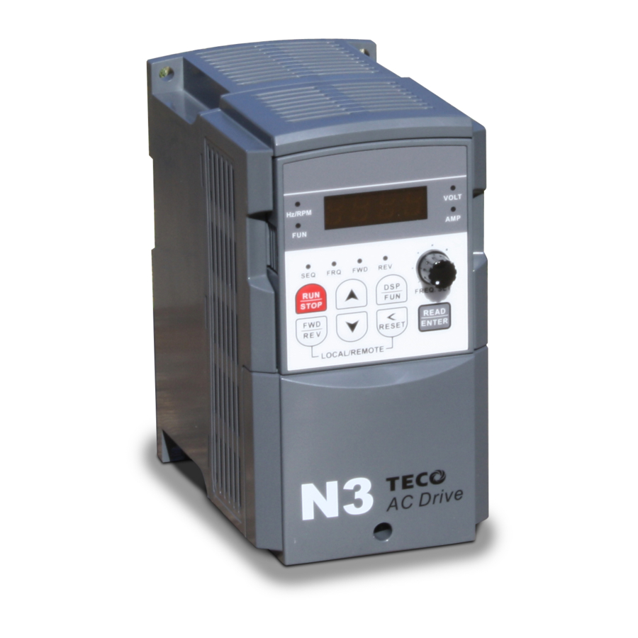
Page 26: Keypad Key Functions And Navigation
N3 Drive Operations Manual 17.0 Keypad Key Functions and Navigation The N3 keypad, provides all the necessary functions to allow full control of the N3 inverter. The keypad has membrane type keys and a 7 - segment 4 - digit LED display. Also located on the keypad is a potentiometer that can be used to control inverter output frequency when selected as the control source. -
Page 27: Key Functions
N3 Drive Operations Manual 17.3 Key Functions The keys are multifunctional, providing for both control of the inverter when keypad mode is selected (default) and access in setting various parameters. The key functions are as follows. Table 17.2 UP / DOWN ·... -
Page 28: Keypad Navigation
N3 Drive Operations Manual 17.4 Keypad Navigation When attempting to control and set various parameters for the inverter it would be useful for the user to become familiar with keypad navigation and to go through a few function changes before making the final settings. 17.4.1 Basic Keypad Control (Factory Default, b000=0000 &... -
Page 29: Setting Parameters B(Basic) And A(Advanced)
N3 Drive Operations Manual 17.4.3 Setting Parameters b(Basic) and A(Advanced) The accessing and setting of parameter groups b and A will be discussed next. Important ! The A (Advanced) parameters are not directly accessible and must be enabled by setting parameter b011=0001. -
Page 30: Control Mode Selection
(3) The specifications of the inverter and motor differ by more than 1 HP. In V/f control, A001 - A005 max. & min. values are determined by the TECO standard motor specification limit. When parameter A000 = 2 (V/f control), the keypad will display ‘Err2’ if Auto tuning is performed. -
Page 31: B (Basic) And A (Advanced)Parameters Defined
N3 Drive Operations Manual 19.0 b (Basic) and A (Advanced) parameters defined. The N3 inverter has two programmable function parameter categories; A (Advanced) and b (Basic) which are described in detail in this section. It is important to note that while the parameters are set individually, they are interactive with other parameters and must be considered when adjusting the value. - Page 32 N3 Drive Operations Manual Parameter Factory LCD Display Description Range/Code Remarks Setting 0000: Keypad 0001: Potentiometer on Keypad 0002: External Analog Signal Input Frequency or Remote Potentiometer Frequency b004 Command Source 0003: Up/Down Frequency Control 0000 Source Selection Using MFIT (S1 - S6) 0004: Communication setting frequency 0005: Pulse Follower...
-
Page 33: B (Basic) Parameter Details
N3 Drive Operations Manual 19.2 b (Basic) Parameter Details 0000: Keypad b000 Run Command Source Selection 0001: External terminal control 0002: Communication control 1.) b000 = 0000: The inverter is controlled by the keypad. 2.) b000 = 0001: The inverter is controlled by the external terminals. The Stop key will function as an emergency stop function. - Page 34 N3 Drive Operations Manual b001 = 2 Three wire mode b001 = 0 Run/Stop/Reverse b001 = 1 Run/Reverse/Stop b001 (Control Method Sequences) Fig. 19.2 0000: Enable Reverse Command b002 Disable Reverse Command 0001: Disable Reverse Command b002 = 0001: The reverse command is invalid. 0000: Controlled Deceleration-to- Stop with b003 Stopping Method...
- Page 35 N3 Drive Operations Manual b005 Frequency Upper limit 0.01 - 400.00 (Hz) b006 Frequency Lower limit 0.01 - 400.00 (Hz) (see note below) b005 (Frequency upper limit) b006 (Frequency lower limit) Frequency command b005 & b006 (Frequency Reference Limits) Fig. 19.3 Note: When b006 = 0 Hz and the frequency command is 0 Hz, the inverter will stop at 0 speed.
- Page 36 N3 Drive Operations Manual 0000: Disable Bus Voltage Display DC Bus Voltage Display b015 0001: Enable Bus Voltage Display Selection 0000: Disabled b016 PID Feedback Display 0001: Enable 1.) The keypad displays the PID feedback value when: · A140=0001 (PID is enabled) ·...
-
Page 37: A (Advanced) Parameter Summary
N3 Drive Operations Manual 19.3 A (Advanced) Parameter Summary Parameter Factory LCD Display Description Range/Code Remarks Setting 0000: Vector (Constant Torque) A000 Control Mode Control Mode 0001: Vector (Variable Torque) 0002 0002: Volts/Hz Motor Rated Motor Rated Voltage A001 Volt (Vac) Motor Rated Motor Rated Current... - Page 38 N3 Drive Operations Manual Parameter Factory LCD Display Description Range/Code Remarks Setting Auto Restart Number of Auto A018 0 - 10 Restart Attempts Auto Restart Auto Restart Delay A019 0.0 - 800.0 Delay Time (Seconds) 0000: Enable Reset Only when Run Reset Mode Command is Off A020...
- Page 39 N3 Drive Operations Manual Parameter Factory LCD Display Description Range/Code Remarks Setting 0000: Disable Parameter 0001: Inverter to Copy Unit A040 Copy Unit 0000 Copy 0002: Copy Unit to Inverter 0003: Verify Copy Operation 0000: Auto (Depend on drive temperature.) A041 Fan Control Fan Control...
- Page 40 N3 Drive Operations Manual Parameter Factory LCD Display Description Range/Code Remarks Setting 0000: Forward/Stop Command 0001: Reverse/Stop Command 0002: Frequency Command 2 (A062) S1 Terminal Multifunction Input 0003: Frequency Command 3 A050 0000 Term. S1 (A063) 0004: Frequency Command 4 (A065) 0005: Jog 0006: Acc/Dec # 2...
- Page 41 N3 Drive Operations Manual Parameter Factory LCD Display Description Range/Code Remarks Setting 0000: When the terminals are Programmed for Up/Down Frequency Control, the Set Frequency will remain when the Drive stops. When the Drive stops, Up/Down Function Disabled. 0001: Up/Down is used. The preset Up/Dn Stop Stop Mode Using A058...
- Page 42 N3 Drive Operations Manual Parameter Factory LCD Display Description Range/Code Remarks Setting Auto_Run Mode Auto_ Run Sel A075 Operation Selection 5 Auto_Run Mode Auto_ Run Sel A076 Operation Selection 6 Auto_Run Mode Auto_ Run Sel (0-3600 sec) 0000 A077 Operation Selection 7 Auto_Run Mode Auto_ Run Sel...
- Page 43 N3 Drive Operations Manual Parameter Factory LCD Display Description Range/Code Remarks Setting 0000: Auto Run mode not effective 0001: Auto Run mode for cycle. (continue running from the unfinished step if restarting) 0002: Auto Run mode performed periodically (continue running from the unfinished step if restarting) 0003: Auto Run mode for cycle, then...
- Page 44 N3 Drive Operations Manual Parameter Factory LCD Display Description Range/Code Remarks Setting 0000: Run 0001: Frequency Reached (Frequency Command) (Set Frequency ± A108) 0002: Set Frequency (A107 ± A108) 0003: Frequency Threshold Level (> A107) - Frequency Reached 0004: Frequency Threshold Level (<...
- Page 45 N3 Drive Operations Manual Parameter Factory LCD Display Description Range/Code Remarks Setting Deceleration Time 0.1 – 3600.0 A118 Dec Trip Time In Trip Prevention Mode (Seconds) Electronic Motor 0000: Enable Electronic Motor Overload Overload Protection A119 Motor OL1 Sel 0000 Protection 0001: Disable Electronic Motor Operation Mode...
- Page 46 N3 Drive Operations Manual Parameter Factory LCD Display Description Range/Code Remarks Setting Motor Slip 0.0 – 100.0 A131 Motor rated Slip 1 & 6 Compensation (%) Maximum 50.00/ A132 Max frequency 0.20 - 400.00 4 & 6 Frequency (Hz) 60.00 Maximum Frequency 0.0 - 100.0 (l 100% based on AC...
- Page 47 N3 Drive Operations Manual Parameter Factory LCD Display Description Range/Code Remarks Setting 0000: Disabled 0001: Enabled - Drive Continues to Feedback Loss A148 Fdbk Sel Operate After Feedback Loss 0000 Detection Mode 0002: Enabled - Drive "STOPS" After Feedback Loss Feedback Loss A149 Fdbk Lvl...
- Page 48 N3 Drive Operations Manual Parameter Factory LCD Display Description Range/Code Remarks Setting 0000 : NONE 0001 : FPM (feet per minute) 0002 : CFM (cubic feet per minute) 0003 : PSI (pounds per square inch) 0004 : GPH (gallons per hour) 0005 : GPM (gallons per minute) 0006 : in 0007 : ft...
- Page 49 N3 Drive Operations Manual Parameter Factory LCD Display Description Range/Code Remarks Setting 0000: 4800 Baud Rate Setting 0001: 9600 A164 Se Baud Rate 0003 (bps) 0002: 19200 0003: 38400 0000:1 Stop Bit A165 Comm Stop Bit Stop Bit Selection 0000 0001: 2 Stop Bits 0000: Without Parity Comm Parity...
-
Page 50: A (Advanced) Parameter Details
N3 Drive Operations Manual 19.4 A (Advanced) Parameter Details 0000: Vector mode (Vector CT Mode) A000 Control Mode 0001: Vector mode (VT Mode) 0002: V/F mode Select the appropriate vector control mode or V/F mode in accordance with the load characteristics. 1.) Vector (Vector CT mode) is best suited to control rapidly-changed torque loads. - Page 51 N3 Drive Operations Manual 0000: Normal Start A012 Starting Method Selection 0001: Enable Speed Search 1.) A012 = 0000: At start, the inverter accelerates from 0 to the target frequency in the set time. 2.) A012 = 0001: At start, the inverter accelerates to the target the frequency from the detected speed of the motor. 0000: Momentary Power Loss and Restart Disable 0001: Momentary Power Loss and Restart is...
- Page 52 N3 Drive Operations Manual 2.) A018>0 and A019 = 0: The inverter will conduct a spin start 0.5 seconds after fault trip. The motor will run to the frequency at the trip point and then to set frequency at the selected acceleration and deceleration times.
- Page 53 N3 Drive Operations Manual 8.) During the acceleration and deceleration process, there may be a residual error in Acceleration and deceleration toggling. If you need to toggle the acceleration and deceleration time during the acceleration / deceleration process, set the S curve time (A023 / A024) = 0 sec. S Curve time Time S Curve characteristics...
- Page 54 N3 Drive Operations Manual 0000: Enable all Functions 0001: A059 - A068 cannot be changed 0002: All Functions Except A059 - A068 Parameter lock function cannot be changed 0003: Disable All Functions 0000: Disable 0001: Inverter to Copy Unit A040 Parameter Copy 0002: Copy Unit to Inverter 0003: Verify...
- Page 55 N3 Drive Operations Manual 2 – 16 KHz A044 Carrier Frequency (KHz) Carrier Carrier Carrier Carrier A044 A044 A044 A044 Frequency Frequency Frequency Frequency 2KHz 6KHz 10KHz 14KHz 3KHz 7KHz 11KHz 15KHz 4KHz 8KHz 12KHz 16KHz 5KHz 9KHz 13KHz Note: Increasing the carrier frequency will generally result in lower audible noise from the motor. However, increased carrier frequencies can potentially cause electrical interference on other equipment operating in proximity to the N3 inverter.
- Page 56 N3 Drive Operations Manual 0000: Forward/Stop Command 0001: Reverse/Stop Command 0002: Frequency Command 2 (A062) 0003: Frequency Command 3 (A063) 0004: Frequency Command 4 (A064) 0005: Jog 0006: Acc/Dec time # 2 0007: Emergency Stop Contact A 0008: Base Block Contact A 0009: Speed Search Stop 0010: Energy Saving Multifunction input terminals...
- Page 57 N3 Drive Operations Manual Multifunction Multifunction Multifunction Jog Command Output terminal 3 terminal 2 terminal 1 terminal frequency Preset value=04 Preset value =03 Preset value =02 Preset value =05 preset value A061 A059 A062 A063 A064 A065 A066 A067 A068 1 = ON, 0 = OFF, &...
- Page 58 N3 Drive Operations Manual ON: The inverter is controlled by the keypad regardless of the settings of b000 (Run source) and b004 (Frequency source). The RS485 communication can still read and write the inverter parameters. 11. 0013: (Disable acceleration and deceleration) When ON, acceleration and deceleration is disabled until the input is turned OFF.
- Page 59 N3 Drive Operations Manual Operation Down A061 Time Up / Down key sequencing Fig. 19.8 13. 0016: (Auxiliary speed toggle) OFF: The frequency is set by the potentiometer (Master Speed) on the keypad. ON: The frequency is set by the AUX. input signal terminal (Auxiliary Speed) on TM2. b004 = 0001: If one of the parameters in group A050 - A056 is set to 16 and the multifunction terminal is OFF, the frequency is set by the potentiometer on the keypad.
- Page 60 N3 Drive Operations Manual 19. A056 = 0023: (Analog input AIN) The multifunction analog terminal AIN = 0023, controlling the output frequency. 20. A050 = 0024: (Multi-Sequence Control) The Multi-Sequence control is set to 0024 to become the input terminal for the Auto – Run mode. Multifunction terminals S1 - S6 A057 and AIN signal scan times...
- Page 61 N3 Drive Operations Manual Function Description Range/Code Factory Setting Code No. Display A059 (Jog Freq) Jog Frequency (Hz) 0.00 - 400.00 2.00 A061 (Freq Command 1) Frequency Command 1 (Hz) 0.00 - 400.00 5.00 A062 (Freq Command 2) Frequency Command 2 (Hz) 0.00 - 400.00 5.00 A063...
- Page 62 N3 Drive Operations Manual 2.) A060 = 0.01 to 5.00: When the Up / Down terminal is ON, the output frequency steps at the incremental frequency set by A060. If Up / Down signal is ON for more than 2 seconds, the output frequency will ramp continuously toward the frequency limits until it is turned OFF.
- Page 63 N3 Drive Operations Manual A081 A082 A083 0000: Stop A084 Auto_Run Stop 0001: Forward A085 0002: Reverse A086 A087 A088 0000: Auto Run Mode Not Effective 0001: Auto Run mode for one cycle. (continue running from the unfinished step if restarting) 0002: Auto Run mode is performed periodically (continue running from the unfinished step if restarting)
- Page 64 N3 Drive Operations Manual (A063) 50Hz (A062) 30Hz (A061) 15Hz (A064) 20Hz (A072) (A071) (A073) (A074) Single Cycle Auto Run Example Fig. 19.12 (B) Periodic Running - (A091=0002 and 0005) In this example the inverter will repeat the same cycle periodically. (A063) (A063) 50Hz...
- Page 65 N3 Drive Operations Manual (D) A091 = 0001 - 0003: If the inverter stops and re-starts, it will continue running from the unfinished step, according to the setting of A091. = 0004 - 0006: If the inverter stops and re-starts, it will begin a new cycle and continue running according to the setting of A091.
- Page 66 N3 Drive Operations Manual NOTE: Refer to the example tables and figures below for additional information b. setting a. setting A94 A95 A97 A94 A95 A97 C 100% 050% 000 001 100% A 100% 050% 000 000 100% D 100% 000% 000 001 100% B 100% 000% 000 000 100% Bias Bias...
- Page 67 N3 Drive Operations Manual 0.001 – 9.999 Pulse input frequency ratio When the frequency source parameter b004 is = 0005 (pulse follower), the actual command frequency will be determined by the pulse input signal frequency and parameter A098. The inverter command frequency = (input pulse frequency) x A098 (times ratio) Example: when the input pulse frequency is = 1KHz (1000), and A098 is set at 1.50, the inverter frequency command is 1000 x 1.5 = 1500 / 100 = 15.00HZ.
- Page 68 N3 Drive Operations Manual V (FM+) Parameter A103 vs FM+ Output Fig. 19.18 0000: Run 0001: Frequency Reached (Target Frequency) (Frequency Reference ± A108) 0002: Set Frequency (A107 ± A108) 0003: Frequency Threshold Level (> A107) – Frequency Reached A105 Relay 1 (R1C,R1B,R1A terminals 0004: Frequency Threshold Level (<...
- Page 69 N3 Drive Operations Manual The following Fig.’s show some examples of the functions of output relays R1 (A105) and R2 A106) If Inverter is Stopped the Relay will not Operate Command STOP (b000) Frequency Reference (b004) Target frequency detection range (A108) Inverter Output Frequency...
- Page 70 N3 Drive Operations Manual Command STOP (b000) Output Freq. Detection Level (A107) Inverter Output Frequency Output Freq. Detection Level (A107) Relay Output Signal A105 / A106 = 03 Frequency Threshold Level (Set Frequency > A107) Fig. 19.21 Command STOP (b000) Output Freq.
- Page 71 N3 Drive Operations Manual (A125) Over Torque Detection Level (100 – 200 %) Output Current Over Torque Output (A126) (A105/A106 = 05) Over Torque Activation Delay Time (0 – 25 sec.) A105 / A106 = 05 Over Torque Detection Fig. 19.23 0000: Enable Trip Prevention During Trip Prevention Selection Acceleration...
- Page 72 N3 Drive Operations Manual 0000: Enable Electronic Motor Overload Electronic Motor Overload Protection A119 Protection Operation Mode 0001: Disable Electronic Motor Overload Protection 0000: Electronic Motor Overload Protection Set for Non-Inverter Duty Motor A120 Motor Type Selection 0001: Electronic Motor Overload Protection Set for Inverter Duty Motor 0000: Constant Torque (OL=103%)(150%, Motor Overload Protection...
- Page 73 N3 Drive Operations Manual Rated Current Rated Current Rated Frequency Rated Frequency 0.13 A Non-Inverter duty motor OL1 protection curve B Non-Inverter duty motor OL1 protection curve OL = 103% Start , 150% / 1 Min. OL = 113% Start , 123% / 1 Min. Rated Current Rated Current Rated Frequency...
- Page 74 N3 Drive Operations Manual Under Torque: A124 = 0000: When there is under torque, the inverter will continue to run and flashes “OL4” until the output torque increases to more than the A127 set value. = 0001: When there is under torque, the inverter coasts to stop and flashes “OL4”. After the fault clears, the “Reset”...
- Page 75 N3 Drive Operations Manual 2.) b009 = 00 – 17 V/f Pattern (Refer to Table ) b009 V/f pattern b009 V/f pattern V (%) V (%) 1.5 2.5 50 400 Hz 1.5 3.0 60 400 Hz V %) V (%) 1.3 2.5 50 400 Hz 1.5 3.0...
- Page 76 N3 Drive Operations Manual 3.) Parameter b009 (00 – 17) sets the V/f pattern. The value of the output voltage is set as a percentage of maximum by the values of B and C at the frequencies shown. The starting torque can be increased by parameter A129 (torque boost gain) as shown in the fig.
- Page 77 N3 Drive Operations Manual Example: 4 Poles,60Hz induction motor synchronization speed × 60 = 1800 RPM Note: Motor no load current (A130) differs with the inverter HP capacities (see parameter A175) and should be set to actual values. (Refer to A002 note) 0000: PID disable 0001: PID enable (Deviation is D-controlled) 0002: PID Feedback D-controlled...
- Page 78 N3 Drive Operations Manual 0000: Positive Direction A145 PID Offset 0001: Negative Direction A146 PID Offset Adjust (%) -109% - +109 % A145 / A146: PID the calculated result pluses A146 (the sign of A146 is determined by A145). A147 Output Lag Filter Time (sec.) 0.0 - 2.5 Sec.
- Page 79 N3 Drive Operations Manual Feedback Loss Detection 0 – 100 % A149 Mode (%) A149: Sets the percentage level for the feedback signal loss detection. The Error in percent = (Set point – feedback value). When the error is larger than the loss level setting, the feedback signal is considered lost. Feedback Loss Detection A150 0.0 -25.5 Sec.
- Page 80 N3 Drive Operations Manual Sleep point based Wake point based on output on PID output frequency A155 Sleep Level A156 Inverter sleep condition Sleep (0 Hz output) Delay Wake Point Internal RUN command External RUN command Inverter output frequency PID output frequency Sleep Level Hz (Set by A155) PID Sleep / Wake Mode Fig.
- Page 81 N3 Drive Operations Manual 0000: Deceleration to stop (b008: Deceleration time 1). Communication time-out 0001: Free run to stop. A161 Operation selection. 0002: Deceleration to stop (A026: Deceleration time 2). 0003: Continue operating. Communication time-out 00.0 – 25.5 Sec. A162 Detection time.
- Page 82 N3 Drive Operations Manual RS485 Communication Station A163 1 - 254 Drop Number A163: Assigns a node number to a specific inverter when networking multiple inverters using RS485 protocol. 0000: 4800 0001: 9600 A164 Baud Rate setting (bps) 0002: 19200 0003: 38400 0000: 1 stop bit A165...
- Page 83 N3 Drive Operations Manual A175 Drive Horsepower Code See table below A175 Inverter Model A175 Inverter Model 2P5-SC/SCF/C 401-C/CF 201-SC/SCF/C 402-C/CF 202-SC/SCF/C 403-C/CF 203-SC/SCF/C 405-C/CF 205-C 407-C/CF 207-C 410-C/CF 210-C 415-C/CF 215-N1 420-N1 220-N1 425-N1 225-N1 430-N1 230-N1 440-N1 240-N1 450-N1 460-N1 475-N1...
- Page 84 N3 Drive Operations Manual 1110: Reset to the 50Hz factory setting A181 Reset to the factory setting 1111: Reset to the 60Hz factory setting A181: Is set to 1110 when the inverter is used with motors rated at 50Hz. A181: Is set to 1111 when the inverter is used with motors rated at60Hz. Note: Motor parameters (A168 - A172) will be modified when in V/F control mode after a factory reset is performed.
-
Page 85: Option Modules And Cables
N3 Drive Operations Manual 20.0 Option Modules and Cables The following Option Modules are available for the N3 Inverter series. They are easily installed and are inserted into connector CON2 by removing the front cover. CAUTION When installing option modules, make sure that power has been removed from the inverter and that the charge indicator is extinguished before proceeding. - Page 86 N3 Drive Operations Manual 3.0 /76.2 1.16 /29.5 (LED Keypad only) 0.56 /15 0.75 /19 M3 x P0.5 (Qty 2) Cable Connector (see table) 2.52 /64 3.23 /82 Potentiometer 1.43 /36.2 1.82 /46 (LED Keypad Only) 0.75 /19 0.16 /4 Note : Dimensions are given in (in ./ mm) Fig.
-
Page 87: Fig. 20.5 Copy Module P/N Sif-Mp
N3 Drive Operations Manual 1Ø / 3Ø Input Voltage NOTE: Use isolated RS232 / RS485 N3 Inverter converter connections between PC and option card to avoid equipment Series damage. CON2 SIF-232 RS232 Fig. 20.4 RS232 Interface P/N SIF-232 1Ø / 3Ø Input Voltage N3 Inverter Series... -
Page 88: Error Display Codes
N3 Drive Operations Manual 21.0 Error Display Codes The following tables describe the error codes that are displayed under fault conditions. They are broken down into five categories: · Unresettable / Unrecoverable errors · Errors recoverable both manually and automatically ·... - Page 89 N3 Drive Operations Manual Overcurrent at The preset deceleration time is Set a longer deceleration time. OC-D deceleration too short. (Parameter b0008) 1. Acceleration time is set too 1. Set a longer acceleration time. short. (Parameter b0007) 2. Replace inverter with the same 2.
-
Page 90: Manually Recoverable Errors Only (No Auto-Restart)
N3 Drive Operations Manual 21.3 Manually Recoverable Errors Only (no auto-restart) Display Fault Cause Remedy 1. OC detection circuit Over-current during malfunction. Send the inverter back for repair. stop 2. Bad connection for CT signal cable. 1. Motor under-sized. 1. Increase motor capacity. 2. -
Page 91: Keypad Errors
N3 Drive Operations Manual 1. If the inverter is set to external control mode (b000 = 0001), and the Stop key is pressed (A010 = 0000), the inverter will stop based on the setting of B003 and STP2 will flash. Turn the run switch to OFF and then ON again to restart the inverter. -
Page 92: Troubleshooting
N3 Drive Operations Manual 1. Faulty / incorrect wiring. 1. Check hardware and wiring. 2. Check parameters A161 – 2. Incorrect settings of communication Communication parameters. A164. Err6 failure 3. Check-sum error 4. Incorrect communication verification. Incorrect 1. Attempt to change A175. Reset inverter or contact parameter 2. -
Page 93: General Troubleshooting
N3 Drive Operations Manual 22.1 General Troubleshooting Fault Check That: Remedy Status · Apply power there is power applied to terminals L1(L), L2, · Turn power OFF and then ON again. and L3(N) (L1(L) and L3(N) for single phase · Make sure the input voltage is correct. units) ·... -
Page 94: Flow Charts
N3 Drive Operations Manual N3 fault Is fault known ? Any symtoms of Symtoms other than damaged Check damaged parts parts or blown fuses damaged parts ? * DM – Power diode module Is the main circuit DM Replace *DM fault signal ? intact ? Check according to fault... - Page 95 N3 Drive Operations Manual N3 fault Continue from previous page Check inverter parameters Initialize parameters Specify operation control mode Fwd or Rev LED Replace control board flashing ? Set up frequency command Is the frequency displayed on the Replace control board digital operator ? Is there motor output voltage at Replace control board...
- Page 96 N3 Drive Operations Manual N3 OC and OL errors Are the IGTB modules Replace IGBT modules functioning ? Are there any visual Replace faulty parts abnormalties ? Apply power Are there any Are the current abnormal indications ? detectors ok ? Replace current controller Input operational command Replace control board...
- Page 97 N3 Drive Operations Manual N3 OV and LV errors Is the main circuit fuse Replace fuse ok ? Are there any visual Replace faulty parts abnormalties ? Apply power Are there any Replace control board abnormal indications ? Input operational command Is the Fwd LED on ? Replace control board Input frequency command...
-
Page 98: Fig. 22.4 Motor Will Not Run
N3 Drive Operations Manual Motor will not run is MCCB On ? is MCCB Wiring short circuit tripped ? Are voltages Input voltage or wiring is Between power terminals incorrect correct ? Yes (Note 1) Is the charge indicator N3 fault LED on ? Is the the run command Turn on the run command... -
Page 99: Fig. 22.5 Motor Overheating
N3 Drive Operations Manual Motor overheats Is the load or current Reduce the load or increase exceeding the the inverter the inverter and / or the motor. rating ? Is the the motor Replace motor with one of running at low speed proper duty rating for an extended time ? Is there output voltage... -
Page 100: Routine Periodic Inspection
N3 Drive Operations Manual 23.0 Routine periodic inspection To ensure safe and secure operations, check and maintain the inverter and motor at regular intervals, the table below lists the suggested items to be checked on a periodic basis. DANGER To prevent injury to personnel and damage to the equipment, wait 5 minutes after the “charge indicator”... -
Page 101: Appendix A - Specifications
N3 Drive Operations Manual Appendix A - Specifications AA.1 General Specifications N3 Series V/F or current vector control Control Mode 0.1 - 400.0 Hz Range 150%/1Hz (current vector) Starting control torque 50:1 (current vector) Speed control range ±0.5% (current vector) - Page 102 N3 Drive Operations Manual 1. RS232 or RS485 2. Multiple inverter networking (RS485 ONLY). Communication control 3. Baud rate, stop bit and parity can be set. 20% - 100% for models with built-in braking transistor and braking resistor. Braking torque 14-120°F (-10 - 50°C) (Note3) Operation temperature - 4 to 140°F (-20 to 60°C)
-
Page 103: Aa.2 Product (Model) Specifications
N3 Drive Operations Manual AA.2 Product (Model) Specifications Single Phase, 200-240V N3- 2 xx- C S Horsepower(HP) 0. 5 Max applicable motor output 0. 4 0. 7 5 1. 5 2. 2 (KW) Rated output current(A) 3. 1 4. 5 7. - Page 104 N3 Drive Operations Manual Three Phase, 380 – 480V l cont. Max. input voltage Thr e e Ph a se: 3 80 - 4 8 0 V + 10% - 1 5% , 5 0/ 60 H Max. output voltage Thr e e Ph a se: 38 0 - 4 80 V Input current(A) 4.
- Page 105 N3 Drive Operations Manual Appendix B - N3 Motor Internal Parameter List Initial (Factory) setting of the motor internal parameters: Motor Data Parameters * A001 A002 A003 A004 A005 A168 A169 A170 A171 A172 Rated Rated Rated Rated Rated Stator Rotor Equivalent Magnetizing...
- Page 106 N3 Drive Operations Manual Appendix C – Table C - N3 Envelope Dimensions and Weights vs Model No. Approx. Envelope Dimensions - Inches / ( mm ) Frame Model No. Size Lbs. / Kg 230V 1 Phase Input N3 – 2P5 - CS 6.42 3.54 5.79...
-
Page 107: Appendix D -N3 Cover Removal Procedure For Various Frame Sizes
N3 Drive Operations Manual Appendix D – N3 Cover Removal Procedure for Various Frame Sizes The following Fig.’s show the cover removal for the various N3 frame sizes 1 thru 6. The Models correlating to the frame sizes are covered in Appendix C. DANGER Do not Remove any covers while power is supplied to the equipment as lethal voltages are present. - Page 108 N3 Drive Operations Manual Finger Removal Grips Mounting (Both sides) Screws Cover Removal Procedure 1 – First remove the Digital Operator by gripping at the points shown and pulling straight out. (The Digital Operator has a connector that plugs directly into Operator to the chassis.) 2 –...
-
Page 109: Appendix E- Emc Filter Dimensions
N3 Drive Operations Manual Appendix E – EMC Filter Dimensions Filter Dimensions The following Fig.’s AE.1– AE.3 show the dimensions of the filter models covered in Section 16.0. The electrical connections and specifications will be covered by the cut sheet received with the specific filter. L1 L2 L3 (4) Mounting Holes... -
Page 110: Ae.2 Kmf Type
N3 Drive Operations Manual 0.28 (7) Dia. 4 Mounting holes Fig. AE.2 KMF Type Filter Model KMF Dimensions in. (mm) KMF370A 3.66 (93) 3.11 (79) 12.3 (312) 11.7 (298) 7.48 (190) KMF3100A KMF3150A 4.96 (126) 4.41 (112) 12.3 (312) 11.7 (298) 8.82 (224) KMF3180A Cont. -
Page 111: Ae.3 Jun Type
N3 Drive Operations Manual 2.76 / 70 3.94 / 100 (4) 0.26 / 6.5 Mounting Slots LINE 9.84 / 250 8.86 / 225 JUNF34048S-MA LOAD * in. / mm 1.97 / 50 Fig. AE.3 JUN Type Filter NOTES: Appendix E- EMC Dimensions, JUN Type Filter... -
Page 112: Appendix F- Inverter Parameter Setting List
N3 Drive Operations Manual Appendix F – Inverter Parameter Setting List Customer: N3 Model No. Site: Equipment: Para Setting Para Setting Para Setting Para Setting Para Setting Para Setting A037 A074 A111 A148 b000 A000 b001 A001 A038 A075 A112 A149 b002 A002... -
Page 113: Appendix G- Version 1.3 Changes
N3 Drive Operations Manual Appendix G – Version 1.3 Changes Overview The changes to the N3 inverter for firmware Version 1.3 consist of some hardware and A (advanced) parameter additions and modifications. Basically for models in the 3 – 75 HP range, the control terminal digital and analog grounds were isolated from each other and the S6/AI2 multifunctional input terminal was separated into two terminals where S6 is exclusively a digital input and AI2 is exclusively an analog input. - Page 114 N3 Drive Operations Manual Factory VER. Parameter LCD Display Description Range Setting AI2 Gain (%) A097 AI2 Gain 0 - 200 AI2 Gain (%) Prior A097 AI2 Gain 0 - 200 Factory VER. Parameter LCD Display Description Range Setting 0000: AIN = 0 -10V or 0 - 20mA AI2 = 0 -10V or 0 - 20mA 0001: AIN = 0 -10V or 0 - 20mA AIN or AI2...
- Page 115 TECO Electric & Machinery Co., Ltd. TECO Westinghouse Motor Company 10F, NO.3-1, Yuancyu St. 5100 North IH-35 Nangang District, Taipei City 115 Round Rock, TX 78681 Taiwan Telephone: +886 - 2 - 6615 - 9111 Telephone: 512 - 255 - 4141 / 1 - 800 - 279 - 4007...
Need help?
Do you have a question about the N3 Series and is the answer not in the manual?
Questions and answers