Table of Contents
Advertisement
Quick Links
ControlBridge Processor
User Manual
Control and Manage Critical Systems using the ControlBridge Processor.
Order toll-free in the U.S. or for FREE technical support: Call 877-877-BBOX
Contact
(outside U.S. call 724-746-5500)
Information
www.blackbox.com • info@blackbox.com
CB-CP100
CB-ACC-232DTE-30
CB-CP200
CB-ACC-232DCE-30
CB-ACC-IR-UNI CB-APP-LIC
CB-PS-12V.
CB-PS-24V.
CB-CP-RMK .
Advertisement
Table of Contents

Related Manuals for Black Box ControlBridge CB-PS-12V


Summary of Contents for Black Box ControlBridge CB-PS-12V
- Page 1 CB-CP100 CB-ACC-232DTE-30 CB-PS-12V. CB-CP200 CB-ACC-232DCE-30 CB-PS-24V. CB-ACC-IR-UNI CB-APP-LIC CB-CP-RMK . ControlBridge Processor User Manual Control and Manage Critical Systems using the ControlBridge Processor. Order toll-free in the U.S. or for FREE technical support: Call 877-877-BBOX Contact (outside U.S. call 724-746-5500) Information www.blackbox.com •...
- Page 2 Trademarks Used in this Manual Trademarks Used in this Manual Black Box and the Double Diamond logo are registered trademarks of BB Technologies, Inc. Any other trademarks mentioned in this manual are acknowledged to be the property of the trademark owners.
- Page 3 Disclaimer: Black Box Network Services shall not be liable for damages of any kind, including, but not limited to, punitive, consequential or cost of cover damages, resulting from any errors in the product information or specifications set forth in this document and Black Box Network Services may revise this document at any time without notice.
- Page 4 NOM Statement Instrucciones de Seguridad (Normas Oficiales Mexicanas Electrical Safety Statement) 1. Todas las instrucciones de seguridad y operación deberán ser leídas antes de que el aparato eléctrico sea operado. 2. Las instrucciones de seguridad y operación deberán ser guardadas para referencia futura. 3.
-
Page 5: Table Of Contents
Table of Contents Table of Contents 1. Specifications ..................................6 2. Overview ....................................7 2.1 Description ..................................7 2.2 Features ..................................7 2.3 What’s Included ................................8 2.4 Hardware Description ..............................9 2.4.1 ControlBridge Processor 100 (CB-CP100) ......................9 2.4.2 ControlBridge Processor 200 (CB-CP200) ......................10 2.4.3 Accessories ................................. 11 3. -
Page 6: Specifications
Chapter 1: Specifications 1. Specifications Specification CB-CP100 CB-CP200 Approvals Power Supply: IEEE 802.3af CE, FCC, RoHS CE, FCC, RoHS Audio — Line in, LIne out Bidirectional Serial RS-232/485 — Bidirectional Serial RS-232/422/485 — Enclosure Aluminum Aluminum General I/O (Analog In/Digital Out) —... -
Page 7: Overview
This controller comes complete with a web server and allows setup through a standard web browser. Unit programming is based on the Black Box standard programming tool ControlBridge Builder. Both models include a web server and allow for setup through a standard web browser. -
Page 8: What's Included
Chapter 2: Overview 2.3 What's Included Your package should include the following items. If anything is missing or damaged, contact Black Box Technical Support at 877-877-BBOX (2267) or info@blackbox.com. CB-CP100: • (1) ControlBridge 100 • (1) 24-VDC power supply • (1) straight-through Ethernet cable •... -
Page 9: Hardware Description
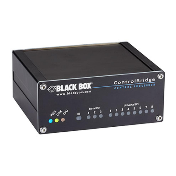
Chapter 2: Overview 2.4 Hardware Description 2.4.1 ControlBridge Processor 100 (CB-CP100) Figure 2-1 shows the ControlBridge Processor 100 (CB-CP100). Table 2-1 describes its components. Versatile ports 105 mm Versatile port indicators Bi-directional serial ports Serial port indicators 24-VDC power supply IR capture sensor System Default button Power, link, and CPU indicators... -
Page 10: Controlbridge Processor 200 (Cb-Cp200)
Chapter 2: Overview 2.4.2 ControlBridge Processor 200 (CB-CP200) Figure 2-2 shows the ControlBridge Processor 200 (CB-CP200). Table 2-2 describes its components. 210 mm Power indicator (blue) Relay 1 - 2 indicators (red) CPU indicator (yellow) General I/O 1 - 4 indicators (green) IR/Serial 1 - 4 indicators (yellow) Ethernet indicator (green) (Link and Activity) -
Page 11: Accessories
Chapter 2: Overview 2.4.3 Accessories IR Adapter The IR Adapter (CB-ACC-IR-UNI) is an infrared emitter that is compatible with IR/serial output and versatile I/O ports. The adapter mounts on the receiver window using double-sided adhesive tape. 2-pin, 3.5-mm IR emitter connector Figure 2-3. - Page 12 Chapter 2: Overview Serial IO Cable DCE The Serial IO Cable DTE (CB-ACC-232DCE-30) is 3.0-m long and supports bi-directional communication between the serial device and the ControlBridge. 5-pin, 3.5-mm DB9 F connector connector (controlled device) Figure 2-5. Serial IO Cable DCE (CB-ACC-232DTE-30). ControlBridge Control Processor 19-inch Mounting K .it (CB-CP-RMK .) The ControlBridge Control Processor 19-inch Mounting Kit (CB-CP-RMK) is a shelf that supports your ControlBridge Processor 100 or 200 in a 19-inch rack.
-
Page 13: Installation
Chapter 3: Installation 3. Installation 3.1 Shelf Placement or Stacking Four rubber feet are provided for shelf placement or stacking. Stick the rubber feet near the corner edges on the bottom side of the controllers - see picture below. Rubber feet Figure 3-1. -
Page 14: Rackmounting
Chapter 3: Installation 3.2 Rackmounting The Rackmounting Shelf (CB-CP-RMK) provides a simple solution for installing controllers in a 19-inch rack. It allows you to install up to two half-rack sized controllers in a single 19-inch unit rack space. All necessary accessories are supplied with the shelf. -
Page 15: Operation
Chapter 4: Operation 4. Operation 4.1 Factory and System Default Settings Every device shipped from the factory is set according to table bellow, Factory Default column. To restore the System Default settings, press the System Default (S.D.) button. This button enables you to connect if you lost the password or if you do not know the IP settings. -
Page 16: Indicators
Chapter 4: Operation Date and time Date and Time Day, month, year Real Not changed Hour, minute, second Real Not changed Time zone (UTC) Coordinated Not changed Universal Time Internet clock Use Internet clock Not changed Primary NTP server Empty Not changed Secondary NTP server Empty... -
Page 17: Ir Sensor
Chapter 4: Operation Table 4-3. Control Port Indicators. Indicator Color On / Flashing ANALOG Yellow Analog output is set to 0 V. Analog output is set to 10 V. Green DALI No data activity. Data activity. DIGITAL I/O Green Output is switched OFF. Output is switched ON. -
Page 18: Capturing Ir Codes
Chapter 4: Operation 4.3.1 Capturing IR Codes All controllers are equipped with an IR capture sensor and are able to capture IR codes. Captured IR codes can be used in both controller models. The capture procedure consists of the following steps: 1. -
Page 19: Ir Control Panels Receiver
Chapter 4: Operation 4.3.2 IR Control Panels Receiver The built-in IR sensor functions the same as other IR receivers. This means that ControlBridge can receive an IR signal from wireless IR control panels without using an external IR receiver. The IR Adapter connects to the rest of the control system via IR communication. -
Page 20: Connecting
Chapter 5: Connecting 5. Connecting The following table describes connections for both controllers. Table 5-1. ControlBridge connections. Unit Connection ControlBridge 100 ControlBridge 200 5.1 Power In The unit requires power 24 VDC from an external power supply. Use any unit ONLY with the power adapter supplied in the product package. -
Page 21: Power Over Ethernet
Chapter 5: Connecting 5.2 Power over Ethernet (PoE) The ControlBridge units are equipped with PoE and are compatible with standard IEEE 802.3af / Class 0 Ethernet with PoE Infrastructure. Ethernet with PoE Ethernet cable Figure 5-2. Ethernet connection with PoE infrastructure. 5.3 ControlBridge Network The ControlBridge links to a 10/100 BASE-T LAN via its RJ-45 connector. - Page 22 Chapter 5: Connecting Direct PC Connection Attach one end of an RJ-45 Ethernet cable to the ControlBridge Network port and attach the other end of the RJ-45 Ethernet cable to your computer. Use straight-through cable if your PC supports autosensing or cross-over cable if your PC doesn’t support autosensing.
- Page 23 Chapter 5: Connecting Windows Local Network Settings Follow these steps for Windows 7: 1. Start Windows 7. 2. Click Start. 3. Enter ncpa.cpl into the Search Box and press Enter. The following window is displayed. Figure 5-5. Windows 7 screen 1. 3.
- Page 24 Chapter 5: Connecting Follow these steps for Windows XP: 1. Start Windows XP. 2. Click Start, then click Control Panel and choose the option to switch to Classic View. 3. Double-click Network Connections. Figure 5-7. Windows XP screen 1. 1. Select Use the following IP address option. Set IP address to 192.168.1.1 (or other address different from 192.168.1.127 and from 192.168.1.128) and Subnet mask to 255.255.255.0.
-
Page 25: Serial
Chapter 5: Connecting 5.4 Serial Table 5-4. Serial ports on the ControlBridge units. Unit Serial port ControlBridge 100 ControlBridge 200 Bi-directional Serial RS-232/485 These bi-directional serial channels are used for RS-232 and RS-485 communication. Maximum speed is 115,200 bps. The default mode for all channels is RS-232;... - Page 26 Chapter 5: Connecting Bi-directional Serial RS-232/422/485 These bi-directional serial channels are used for RS-232, RS-422, and RS-485 communication. The maximum speed is 115,200 bps. The default mode for all channels is RS-232; you must set other modes in the programming application. For more details, see the programming manuals.
-
Page 27: Versatile I/O Ports
Chapter 5: Connecting 5.5 V.ersatile I/O Ports Depending on the application, the versatile I/O ports can be used in multiple ways as described in the following table. Table 5-10. Versatile port functions. Input modes Digital input Adjustable threshold • High sensitivity - binary 0 < 1.45 V, binary 1 > 2.05 V •... - Page 28 Chapter 5: Connecting 2-pin 3.5 mm Signal Description Signal Versatile port signal (input/output) Ground Digital Input Every versatile port can be used as a digital input for contacts, buttons, sensors, etc. For digital input usage, the output must be in an open state and current pull-up and current pull-down can be used. Parameters of pulse counter input are as follows: •...
- Page 29 Chapter 5: Connecting Pulse Counter Pulse counter input parameters are as follows: • Adjustable threshold as above • Input impedance as above • Pulse length min. 1 ms, max. frequency: 500 Hz • Max. number of pulses: 2 147 483 647 (Long) •...
- Page 30 Chapter 5: Connecting The following table describes how to use voltage input. Table 5-14. Voltage input. Detecting a voltage Sensors with voltage output 0 - 10 VDC Max. 10 VDC Reading voltage Potentiometer with external power supply Max. 10 VDC 877-877-2269 | blackbox.com Page 30...
- Page 31 Chapter 5: Connecting Resistance Input Parameters of resistance input are as follows: • Range 2 kohms, 20 kohms, 200 kohms, auto • Resolution 12-bit • Adjustable digital filter • Accuracy (digital filter applied) • 100 ohms to 800 ohms: ±3 % of reading, ±0.1 % of range •...
- Page 32 Chapter 5: Connecting Digital Output For digital output the open collector switch is used. Parameters of digital output are as follows: • Max. sink current 200 mA / max. 30 VDC • Catch diodes for use with real load The following table describes how to use digital output. Table 5-16.
- Page 33 Chapter 5: Connecting IR Output This mode of versatile port provides output for infra-red emitters (IR Adapters). Parameters of IR output are as follows: • The maximum IR carrier frequency is 500 kHz. • Up to three original infra-red emitters (IR Adapters) can be connected to each output in parallel. All emitters send the same IR codes.
- Page 34 Chapter 5: Connecting IR/SERIAL This type of port provides: • Output for infra-red emitters (IR Adapters); the maximum IR output rate is 1.2 MHz. • For RS-232 serial output (one way), the maximum serial data rate is 115 200 Bd (bps), and output signal levels for RS-232 are in the -12 V to +12 V range.
-
Page 35: General I/O
Chapter 5: Connecting 5.6 General I/O General I/O provides analog input as well as digital output. Each General I/O port can be used either as input or as output. A 680-ohms pull-up resistor connects to +5 VDC and can be switched on and off for each I/O independently. I/O voltage with pull-up on is approx. -
Page 36: Relay
Chapter 5: Connecting 5.7 Relay This port provides one isolated low voltage relay. Each relay contact closure is rated 24 V / 0.5 A. Normally Closed (NC) and Normally Open (NO) contacts as well as Common (C) contact of each relay can be used. The Normally Closed (NC) position is the state of the relay when it is not turned on (energized). - Page 37 Chapter 5: Connecting This connector provides un-amplified unbalanced line level audio. Connect audio devices, such as an audio amplifier or powered speakers to this connector. Connector pin out Table 5-21. Audio line out connector pinout. AUDIO LINE OUT 3-pin 3.5 mm Signal Description Left...
-
Page 38: Upload User Application
Chapter 6: Upload User Application 6. Upload User Application The user application is dedicated to control and it is programmed by ControlBridge Builder programming tools. 6.1 Using ControlBridge Builder Follow these steps: 1. Connect the controller to your computer as described in the Connecting / ControlBridge Network chapter. 2. -
Page 39: Using Admin Control Panel
Chapter 6: Upload User Application 6.2 Using Admin Control Panel Follow these steps: 1. Run ControlBridge Builder on your PC. 2. Open a project in ControlBridge Builder. It’s necessary to have the appropriate controller properly inserted and configured. 3. Use the tool bar Final button to open the Upload and Export Application dialog box. Final Button Export As Application Files ... -
Page 40: Admin Control Panel
Chapter 7: Admin Control Panel 7. Admin Control Panel 7.1 Access Admin Control Panel Run the Internet browser on your PC and type in the controller IP address. The factory default IP address is 192.168.1.127. 7.2 Login Figure 7-1. Login screen. This screen isn’t displayed if password is empty (factory default status). - Page 41 Chapter 7: Admin Control Panel IP Settings Figure 7-3. IP Settings tab. This page is used for setting the communication parameters for your ControlBridge Unit. The ControlBridge Unit uses standard internet protocol (IP) communication parameters. Certain parameters can be reset by the user. On start up, this page will display the ControlBridge Unit’s given Physical address (MAC), and Current IP Address.
-
Page 42: Date And Time
Chapter 7: Admin Control Panel Be sure to click the Apply button for any changes to become effective! 7.4 Date and Time Current Date and Time Figure 7-5. Current Date and Time screen. Use this page to set the time clock on your ControlBridge Unit. The current date, time, and time zone are shown on the Current time line. -
Page 43: Applications
Chapter 7: Admin Control Panel Use this page to set the time zone on your ControlBridge Unit. The current date, time, and time zone are shown on the Current time line. Select the time zone box to enter changes to the Time zone. Be sure to click the Apply button for any changes to become effective! Internet Clock Figure 7-7. -
Page 44: File Storage
Chapter 7: Admin Control Panel Use this page to upload compiled ControlBridge Builder programs to your ControlBridge Unit. All uploaded applications are listed on this page, along with their file properties: file name/file size/date. The ControlBridge Unit has a generous memory pool; unused free space is shown at the bottom of this page. The ControlBridge Unit also permits other service functions, including deleting files, downloading programs back to a personal computer, and starting/stopping specific applications. -
Page 45: E-Mail
Chapter 7: Admin Control Panel 7.7 E-mail Figure 7-10. E-mail screen. Use this page to set e-mail parameters and recipients’ addresses. You must set the SMTP server. See the Configuration/SMTP setting. The sender Name and E-mail are the addresses of your ControlBridge Unit. The sender Name and E-mail are used by the XPL2 commands EmailSend and PresetEmailSend. -
Page 46: Password
Chapter 7: Admin Control Panel Information The Information page shows basic information about your ControlBridge Unit’s firmware and version. Format Data Area Figure 7-12. Format Data Area tab. To completely clear all data and restore the factory default settings, click the Format data area button. This will remove all data, including Applications and File storage files. -
Page 47: Backup
Chapter 7: Admin Control Panel You need a case-sensitive password to login to the admin web pages. Set a new password via the New password box. You must reenter the password in the Confirm new password box. An error message will appear if the confirmation does not match, in which case you should reenter your password again in both boxes. -
Page 48: Reset
Chapter 7: Admin Control Panel READ ALL IMPORTANT NOTES THAT FOLLOW BEFORE USING THIS OPERATION! Use this page to restore all applications, files, and folders. Restore copies of all applications, files, and folders from a backup archive on the PC to their corresponding locations on the ControlBridge Unit. To start the restore process, select the desired backup archive, then click the Restore button. -
Page 49: Logout
Chapter 7: Admin Control Panel 7.12 Logout Figure 7-17. Logout screen. This screen isn’t displayed if the password is empty (factory default status). 7.13 License This page describes the software license. Figure 7-18. License screen. 877-877-2269 | blackbox.com Page 49... - Page 50 NOTES 877-877-2269 | blackbox.com Page 50...
- Page 51 NOTES 877-877-2269 | blackbox.com Page 51...
- Page 52 About Black Box Black Box provides an extensive range of networking and infrastructure products. You’ll find everything from cabinets and racks and power and surge protection products to media converters and Ethernet switches all supported by free, live 24/7 Tech support available in 60 seconds or less.
Need help?
Do you have a question about the ControlBridge CB-PS-12V and is the answer not in the manual?
Questions and answers