Advertisement
Quick Links
www.blackboxtoolkit.com
Inserting Decals Under Tamper-Proof
Clear Cap Buttons
Each clear cap button has a pop off clear
cap that can be released from the underside
of the lid.
To release the tamper-proof clear cap you
will need to access the underside of the lid
as described above.
Two clear locking tabs hold the cap in place
(red arrow). Gently push inwards and
downwards on each tab in turn to release
the cap.
You will need to use a long thin flat blade
screw driver or pick/phone opening toolkit
to do this.
Note if you push too hard this could cause
the locking tab to snap off. Snapped tabs
are not covered by the 12 month warranty.
Once the clear cap has been released
(yellow arrow) you can remove the decal
disc (red arrow).
Simply place your own decal on top of the
decal disc and refit.
When putting the clear cap and decal disc
back on to the microswitch ensure that the
keyed parts and tabs are located correctly
before gently pressing down to reseat
(green arrow).
A compass cutter can be used to create decal
labels with a diameter of approximately
21mm.
Compass
cutters
and
phone
opening
toolkits can be sourced cheaply and easily
from online market places such as ebay.
Made in the UK
Serious about science: Serious about timing
The Black Box ToolKit
Measurement & calibration tools for professionals
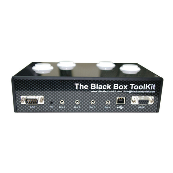
BBTK USB Response Pad
(URP48/URPVK)
4/8 Button USB Response Pad (URP48)
Operating Modes: 1. USB Response Pad: By
default the URP is designed to mimic a standard HID
keyboard when connected via USB. 2. USB & BBTK
Response Pad: The URP can be simultaneously
connected to an experimental PC/Mac that accepts
responses from a keyboard and to a Black Box ToolKit
v2 via the 9-way D labelled BBTK. Ensure you connect
the USB lead first if running in this mode. 3. BBTK Response Pad: To run the URP solely
as a Black Box ToolKit v2 response pad ensure the USB lead is disconnected and then
connect the 9-way D lead whilst holding down button 4.
Troubleshooting: Regardless of operating mode you are advised to check functionality
at the start of each experimental session before you begin to collect data. If connected
to a Black Box ToolKit v2 and the Response Pad LEDs are out of sync, ensure that you
connect the USB first if running in mode 2. USB & BBTK Response Pad. If using the URP
in mode 3. BBTK Response Pad, press button 4 when connecting the 9-way D lead. In this
mode ensure the USB remains disconnected.
Default Button Mappings: In USB, or USB & BBTK Response Pad mode, default keystroke
mappings are as follows: 1 = a, 2 = s, 3 = d, 4 = f, 5 = g, 6 = h, 7 = j, 8 = k.
Button Up Debouncing: A built in debouncing window means that a button must be
cleanly up for 25ms before a button/key up keystroke is sent. This means that button down
durations will be elongated by +25ms. Response Times (RTs) are unaffected as they are
registered on the leading edge of a button down.
TTL Event Markers: A 50ms wide TTL pulse is sent via the 2.5mm stereo socket each
time a button is registered as being down (positive and negative marker available). Four
primary button TTL lines are provided by the BBTK female 9-way D (pins 1-4 = But 1-4, pin
5 = +5V, pins 6-9 = GND). TTL signals from the four primary buttons will be elongated by
+25ms due to button up debouncing.
Active Switch Closure (ASC): This male 9-way D provides four paired lines which can be
used to short other equipments push-to-make buttons when buttons 1 to 4 on the URP are
pressed. As Solid State Relays (SSR's) have been used approx 0.40ms will be added (pins
4&5 = But 1, 2&3 = 2, 1&6 = 3, 7&8 = 4).
External Response Buttons: Up to four external push-to-make buttons can be connected
via the 3.5mm mono sockets labelled But 1 to But 4. WARNING: Use of poor quality
external buttons may adversely affect timing accuracy.
Firmware Updates: For firmware updates & support please visit www.blackboxtoolkit.
com.
www.blackboxtoolkit.com
Advertisement

Related Manuals for Black Box URP48


Summary of Contents for Black Box URP48
- Page 1 If connected to a Black Box ToolKit v2 and the Response Pad LEDs are out of sync, ensure that you connect the USB first if running in mode 2. USB & BBTK Response Pad. If using the URP in mode 3.
- Page 2 PCB. to a Black Box ToolKit v2 and the Response Pad LEDs are out of sync, ensure that you connect the USB first if running in mode 2. USB & BBTK Response Pad. If using the URP in mode 3.
Need help?
Do you have a question about the URP48 and is the answer not in the manual?
Questions and answers