Table of Contents
Advertisement
Quick Links
T1 CSU/DSU Card
CUSTOMER
Order toll-free in the U.S.: Call 877-877-BBOX (outside U.S. call 724-746-5500)
FREE technical support 24 hours a day, 7 days a week: Call 724-746-5500 or fax 724-746-0746
SUPPORT
Mailing address: Black Box Corporation, 1000 Park Drive, Lawrence, PA 15055-1018
INFORMATION
Web site: www.blackbox.com • E-mail: info@blackbox.com
M
O
O
U
N
T
O
T
X
U
T
M
O
I
N
N
R
I
X
N
R E M
O T E
A
G
G
R
E
L
G
O
A
O
L O C
T
A L
P
E
B
R E M
A
O T E
C
K
C
H
A
N
N
E
L
L O C
A L
N
E
B P
V
L O
T
S
W
O
Y E
L R
R
E D
K
T E S
T S Y
N C
C
H
R T
S
N
T D
L
R L
S D
R D
JANUARY 1997
MT510A-R2
Advertisement
Table of Contents

Related Manuals for Black Box T1 CSU/DSU Card


Summary of Contents for Black Box T1 CSU/DSU Card
- Page 1 Order toll-free in the U.S.: Call 877-877-BBOX (outside U.S. call 724-746-5500) FREE technical support 24 hours a day, 7 days a week: Call 724-746-5500 or fax 724-746-0746 SUPPORT Mailing address: Black Box Corporation, 1000 Park Drive, Lawrence, PA 15055-1018 INFORMATION Web site: www.blackbox.com • E-mail: info@blackbox.com...
- Page 2 T1 CSU/DSU CARD FEDERAL COMMUNICATIONS COMMISSION INDUSTRY CANADA RADIO FREQUENCY INTERFERENCE STATEMENTS This equipment generates, uses, and can radiate radio-frequency energy, and if not installed and used properly, that is, in strict accordance with the manufacturer’s instructions, may cause interference to radio communication.
- Page 3 T1 CSU/DSU CARD INSTRUCCIONES DE SEGURIDAD (Normas Oficiales Mexicanas Electrical Safety Statement) 1. Todas las instrucciones de seguridad y operación deberán ser leídas antes de que el aparato eléctrico sea operado. 2. Las instrucciones de seguridad y operación deberán ser guardadas para referencia futura.
- Page 4 T1 CSU/DSU CARD TRADEMARKS USED IN THIS MANUAL Any trademarks mentioned in this manual are acknowledged to be the property of the trademark owners. AT&T is a registered trademark of American Telephone and Telegraph Company.
-
Page 5: Table Of Contents
3. Installation ..............................18 3.1 Unpacking the Card .........................18 3.2 Site Preparation ..........................18 3.3 T-1 Network ............................19 3.4 Installing the T1 CSU/DSU Card Module..................19 4. Configuration .............................23 4.1 Configuration DIP Switches ......................23 4.2 Network Timing ..........................26 4.3 DTE Channel Timing ........................28... - Page 6 T1 CSU/DSU CARD Chapter Page 5. Troubleshooting ............................30 5.1 Power Problems ..........................30 5.2 Network or Port Problems........................30 5.3 Diagnostic Loopbacks........................31 5.4 Calling Your Supplier ........................33 5.5 Shipping and Packaging........................33 Appendix A. FCC Document Requirements ....................34 Appendix B. CPE Affidavit..........................35 Appendix C. Cabling............................38...
-
Page 7: Specifications
T1 CSU/DSU CARD 1. Specifications Configuration and Control (2) 12-switch DIPs Internal CSU Local and remote loopback diagnostics; Type I Keep-Alive signal Internally provided; External from the network Clocking Modes (loop); External from the DTE (channel) Port A (RS-530 physical) selectable for V.35 or DTE Channel RS-449 operations;... - Page 8 T1 CSU/DSU CARD Network Interface Twisted Shielded Pair (TSP) Recommended Cable Line Rate 1.544 Mbps ±50 bps Line Encoding Format AMI or B8ZS Framing Format D4 or ESF Pulse Characteristics AT&T 62411 compliant Output Amplitude 2.4 to 3.3 V peak-to-peak...
-
Page 9: Introduction
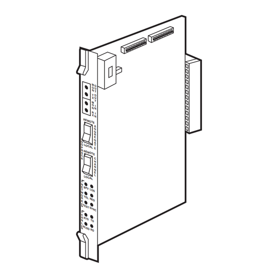
The T1 CSU/DSU Card is a high speed T-1 and Fractional T-1 CSU/DSU-format processor in modular circuit-board form. See Figure 2-1. The T1 CSU/DSU Card is installed vertically into the front of the WAN Rack 16. For additional WAN Rack 16 information, refer to the WAN Rack 16 manual. - Page 10 • Ability to drive T-1 signals (using shielded twisted-pair cabling) up to 6000 feet (1,829 m). The T1 CSU/DSU Card can process digital information from a single high-density DB26, software- selectable DCE port supporting V.35 or RS-449 applications at speeds of either n x 56 Kbps (56, 112, 168, 224, 336, 448, 672, 1344) or n x 64 Kbps (64, 128, 192, 256, 384, 512, 768, 1536), depending on the format and density requirements of the application.
- Page 11 T1 CSU/DSU CARD Figure 2-2. I/O Interface Module.
-
Page 12: Controls And Indicators
To inject and receive a test signal (application data will be interrupted) across the T-1 network, first connect a T-1 test set between the TX OUT jack and the RX IN jack. Then put the T1 CSU/DSU Card diagnostic CHNL loopback switch in the REMOTE position. -
Page 13: Channel Leds
2.2.4 C HANNEL The four channel LEDs, located on the front of the T1 CSU/DSU Card, provide a visual status of channel (DTE) conditions. See Figure 2-1. The information conveyed by each channel LED is described in Table 2-2. -
Page 14: Lbo Switch
T-1 carrier requirements. See Figure 2-3. NOTE Make sure that the LBO switch is in its proper dB position before the T1 CSU/DSU Card is installed in the WAN Rack 16. 2.2.6 C... - Page 15 T1 CSU/DSU CARD 0dB POSITION LBO SWITCH -7.5dB POSITION LBO SWITCH -15dB POSITION LBO SWITCH Figure 2-3. LBO Switch Positions.
-
Page 16: Net Interface
The NET interface may be configured to support various aggregate configurations using the DIP switches located on the T1 CSU/DSU Card. To configure the NET interface, refer to Chapter 4. This interface connector may be cabled to accommodate several different types of configurations. For information on these configurations, refer to Appendix C. -
Page 17: Com A Interface
T1 CSU/DSU CARD 2.2.8 COM A I NTERFACE The COM A interface port, located on the I/O interface module, is not used. 2.2.9 P NTERFACE The Port A interface, located on the I/O interface module, is designed as a DCE interface and provides for the electrical transmission/reception of serial digital information. -
Page 18: Portb Interface
• DTE running RS-449 applications equipped with a 37-pin connector. Attachment to the I/O interface module’s Port A interface is through a 37-pin-to-25-pin adapter cable. 2.2.10 P NTERFACE The Port B interface port, located on the I/O interface module, is not used by the T1 CSU/DSU Card. -
Page 19: Installation
3. Installation 3.1 Unpacking the Card The T1 CSU/DSU Card communication module is shipped in a carton designed to ensure that it arrives at your location safely and undamaged. To unpack and inspect the T1 CSU/DSU Card and its I/O interface module: 1. -
Page 20: Network
T-1 line based on your requirements. • T-1 network specifications include such parameters as encoding methods (AMI or B8ZS) and framing (D4 or ESF). This information will be used when configuring your T1 CSU/DSU Card. • The T-1 line should be Local (non-powered) or “DRY.”... - Page 21 Step Action Configure the two 12-switch DIPs (S1 and S3), located on the T1 CSU/DSU Card module, to support data application and T-1 network requirements. Refer to Chapter 4. Select an unused front chassis slot. All slots have equal access to the chassis’s tri-bus mid-plane.
- Page 22 T1 CSU/DSU CARD Figure 3-1. Installing the T1 CSU/DSU Card Module.
- Page 23 T1 CSU/DSU CARD Figure 3-2. Installing the I/O Interface Module.
-
Page 24: Configuration
4. Configuration 4.1 Configuration DIP Switches The T1 CSU/DSU Card is controlled by a series of DIP-switch settings contained on two 12-switch DIPs located next to the LBO switch. These DIP switches (S1 and S3) are configured to match specific network and application requirements. - Page 25 T1 CSU/DSU CARD SWITCH 1 (S1) 9 10 11 12 Reserved ON: DTE Port A RS-449 enabled. OFF: DTE Port A V.35 enabled. Aggregate Timing (Refer to Section 4.2). ON: RTS always ON. OFF: RTS is Controlled. ON: DTE Channel Data is normal.
- Page 26 T1 CSU/DSU CARD Table 4-1 describes the DIP settings that must be made to support the various n x 56 Kbps and n x 64 Kbps data rates. Table 4-1. Setting Data Rates Data Rate (Kbps) Data Rate Settings DS0s Used...
-
Page 27: Network Timing
Internal (Master) Crystal Timing—Data is transmitted (clocked) to the network with a signal provided by the crystal in the T1 CSU/DSU Card. Timing for the data transmission from the DTE to the T1 CSU/DSU Card is also clocked using this same signal. See Figure 4-2. - Page 28 External Channel Timing—Data is transmitted (clocked) to the network with a signal provided by the DTE. The DTE passes this clock signal to the T1 CSU/DSU Card via Terminal Timing (TT). Timing for the data transmission from the DTE to the T1 CSU/DSU Card is also clocked using this same signal.
-
Page 29: Dte Channel Timing
Send Timing (ST) signal from the T1 CSU/DSU Card. See Figure 4-5. When using Loop 1 Timing, the T1 CSU/DSU Card uses the TT clock signal to gate the Send Data (SD) Function (DTE data) into the network transmit data buffer. Clock function and data are subject to the same delays and attenuation inherent in data transmission. - Page 30 DTE Channel Timing Invert (S1-6) when configuring the T1 CSU/DSU Card. This causes the sampling of the Send Data to occur on the opposite edge of the clock, which should allow for a more acceptable data transfer.
-
Page 31: Troubleshooting
5.1 Power Problems The T1 CSU/DSU Card gets its power entirely from the WAN Rack 16 chassis mid-plane. The loss of mid-plane power will cause a lack of front-panel LED activity (network and channel port). If there is more than one communication module in the chassis, see if each module is experiencing the same symptoms. -
Page 32: Diagnostic Loopbacks
Local Aggregate Loopback—Placing the AGGREGATE LOOPBACK switch in the LOCAL position causes the local T1 CSU/DSU Card to place a loopback on its aggregate in the direction of the DTE channel interface. This diagnostic loopback tests the local DTE channel interface and aggregate. The local module’s front-panel NETWORK LED labeled “TEST”... - Page 33 Local Channel Loopback—Placing the CHANNEL LOOPBACK switch in the LOCAL position causes the local T1 CSU/DSU Card to place a bidirectional loopback on its DTE channel interface and aggregate. These diagnostic loopbacks test the local DTE channel interface and allow testing of the T-1 network path by the remote unit.
-
Page 34: Calling Your Supplier
5.4 Calling Your Supplier If you determine that your T1 CSU/DSU Card is malfunctioning, do not attempt to alter or repair the unit. It contains no user-serviceable parts. Contact your supplier. Before you do, make a record of the history of the problem. Your supplier will be able to provide more efficient and accurate assistance if you have a complete description, including: •... -
Page 35: Appendix A. Fcc Document Requirements
T1 CSU/DSU CARD Appendix A. FCC Document Requirements The following information, which informs the user of his rights and obligations in connecting this equipment to the network and in ordering service, is required by FCC Part 68 Rules. This equipment complies with Part 68 of FCC Rules. Please note the following:... -
Page 36: Appendix B. Cpe Affidavit
T1 CSU/DSU CARD Appendix B. CPE Affidavit Affidavit for the connection of Customer Premises Equipment (CPE) to 1.544 Mbps and/or Subrate Digital Services (SDS) For work to be performed in the certified territory of: (TELCO’s Name) State of: County of:... - Page 37 T1 CSU/DSU CARD CPE Affidavit, continued With respect to encoded analog content and billing protection: I attest that all operations associated with the establishment, maintenance, and adjustment of the digital CPE with respect to encoded analog content and encoded billing information continuously comply with Part 68 of the FCC’s Rules and Regulations.
- Page 38 T1 CSU/DSU CARD CPE Affidavit, continued I agree to provide with proper documentation to demonstrate (TELCO’s) name compliance with the information as provided in the preceding paragraph, if so requested. Signature Subscribed and Sworn to before me Title this day of...
-
Page 39: Appendix C. Cabling
T1 CSU/DSU CARD Appendix C. Cabling Read this appendix before cabling the I/O interface module associated with your T1 CSU/DSU Card communication module. • We recommend using only 100-ohm, 22-AWG individually shielded twisted-pair cables. These cables provide protection from electromagnetic interference (EMI) and crosstalk. - Page 40 T1 CSU/DSU CARD DB15M to DB15M 100-ohm twisted pair DB15F to RJ-48 Splitter to CSU RJ-48 to RJ-48 straight Splitter to CSU A END B END A END B END A END B END RJ-48 RJ-48 DB15 RJ-48 DB15 DB15...
- Page 41 T1 CSU/DSU CARD RJ-48 to RJ-48 RJ-48 to DB25F RJ-48 Straight Special Crossover A END B END A END B END RJ-48 RJ-48 RJ-48 DB25 A END B END RJ-48 RJ-48 RJ-48 to DB25M RJ-48 to DB9F RJ-48 to DB9M...
- Page 42 © Copyright 1997. Black Box Corporation. All rights reserved. 1000 Park Drive • Lawrence, PA 15055-1018 • 724-746-5500 • Fax 724-746-0746...
Need help?
Do you have a question about the T1 CSU/DSU Card and is the answer not in the manual?
Questions and answers