Table of Contents
Advertisement
Quick Links
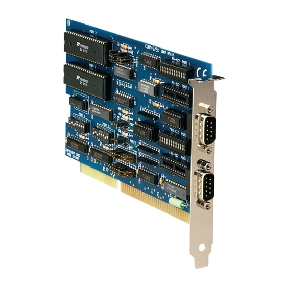
Dual Port RS-232/422/485 Serial Interface
CUSTOMER
SUPPORT
INFORMATION
Order toll-free in the U.S. 24 hours, 7 A.M. Monday to midnight Friday: 877-877-BBOX
FREE technical support, 24 hours a day, 7 days a week: Call 724-746-5500 or fax 724-746-0746
Mail order: Black Box Corporation, 1000 Park Drive, Lawrence, PA 15055-1018
Web site: www.blackbox.com • E-mail: info@blackbox.com
MARCH 2000
IC113C
IC175C
Advertisement
Table of Contents

Related Manuals for Black Box IC113C


Summary of Contents for Black Box IC113C
- Page 1 Order toll-free in the U.S. 24 hours, 7 A.M. Monday to midnight Friday: 877-877-BBOX SUPPORT FREE technical support, 24 hours a day, 7 days a week: Call 724-746-5500 or fax 724-746-0746 Mail order: Black Box Corporation, 1000 Park Drive, Lawrence, PA 15055-1018 INFORMATION Web site: www.blackbox.com • E-mail: info@blackbox.com...
- Page 2 FCC AND IC STATEMENTS, TRADEMARKS FEDERAL COMMUNICATIONS COMMISSION INDUSTRY CANADA RADIO FREQUENCY INTERFERENCE STATEMENTS This equipment generates, uses, and can radiate radio frequency energy and if not installed and used properly, that is, in strict accordance with the manufacturer’s instructions, may cause interference to radio communication. It has been tested and found to comply with the limits for a Class A computing device in accordance with the specifications in Subpart J of Part 15 of FCC rules, which are designed to provide reasonable protection...
- Page 3 DUAL PORT RS-232 422/485 SERIAL INTERFACE NORMAS OFICIALES MEXICANAS (NOM) ELECTRICAL SAFETY STATEMENT INSTRUCCIONES DE SEGURIDAD 1. Todas las instrucciones de seguridad y operación deberán ser leídas antes de que el aparato eléctrico sea operado. 2. Las instrucciones de seguridad y operación deberán ser guardadas para referencia futura.
- Page 4 NOM STATEMENT 11. El aparato eléctrico deberá ser connectado a una fuente de poder sólo del tipo descrito en el instructivo de operación, o como se indique en el aparato. 12. Precaución debe ser tomada de tal manera que la tierra fisica y la polarización del equipo no sea eliminada.
-
Page 5: Table Of Contents
DUAL PORT RS-232 422/485 SERIAL INTERFACE Contents Chapter Page 1. Specifications....................1 2. Introduction ....................2 2.1 Overview ....................2 2.2 What’s Included..................2 2.3 Features ....................3 2.4 Technical Description ................4 3. Address Selection ....................6 4. Option Selection .....................7 4.1 Port Enable/Disable ................7 4.2 RS-232 Interface Options ...............9 4.3 RS-422/485 Interface Options .............10 4.4 Line Termination .................11 5. -
Page 6: Specifications
CHAPTER 1: Specifications 1. Specifications Protocol — Asynchronous Speed — IC113C: Up to 115.2 Kbps; IC175C: 460.8 kbps and higher Operation — RS-232 or RS-485/422, 2- or 4-wire (individually selectable on each port) Connectors — (2) DB9M Communications Chip — IC113C: 16550 UART; IC175C: 16950 UART MTBF —... -
Page 7: Introduction
2.2 What’s Included Your Serial Interface should come with the following items. If any of these items are missing or damaged, contact Black Box at 724-746-5500. (1) Dual Port RS-232/422/485 Serial Interface card, (2) serial utility software diskettes: (1) for 32-bit Windows ®... -
Page 8: Features
• Supports any character set defined by binary notation. • 16550 UARTs on the IC113C help ensure against data loss. This chip features programmable baud rate, data format, interrupt control, and a 16-byte FIFO. The IC175C uses 16950 UARTs, which feature a 128-byte buffer for even better performance. -
Page 9: Technical Description
DUAL PORT RS-232 422/485 SERIAL INTERFACE 2.4 Technical Description The Dual Port RS-232/422/485 Serial Interface utilizes the same 16550 UART chip found in the IBM ® asynchronous adapter. This chip features programmable baud rate, data format, and interrupt control. Refer to the IBM Technical Reference for details on programming the chip. - Page 10 CHAPTER 2: Introduction RS-485 RS-485 is backward-compatible with RS-422; however, it is optimized for multidrop applications. The output of the RS-422/485 driver is capable of being active (enabled) or tri-state (disabled). This capability allows multiple ports to be connected in a multidrop bus and selectively polled. Half-duplex two-wire communications are possible by connecting TX+ to RX+ and TX- to RX- in your cable connector.
-
Page 11: Address Selection
DUAL PORT RS-232 422/485 SERIAL INTERFACE 3. Address Selection NOTE Be sure to set the address selections and jumper options before installation. Each serial port on the Dual Port RS-232/422/485 Serial Interface occupies 8 consecutive I/O locations. DIP switch SW1 sets the base address for Port 1, and DIP switch SW2 sets the address for Port 2. -
Page 12: Option Selection
CHAPTER 4: Option Selection 4. Option Selection NOTE Be sure to set the address selections and jumper options before installation. The board contains several jumper straps for each port which must be set for proper operation. 4.1 Port Enable/Disable Each port on the Dual Port RS-232/422/485 can be enabled or disabled with switch position 8 on the DIP switch. - Page 13 DUAL PORT RS-232 422/485 SERIAL INTERFACE 2/9 3 4 5 7 10 11 12 15 2/9 3 4 5 7 10 11 12 15 Figure 4-1. Header E1 and E2 (IRQ selection). Any two or more ports can share a common IRQ by placing the jumpers on the same IRQ setting, and setting the appropriate selections at E9 and E10.
-
Page 14: Rs-232 Interface Options
CHAPTER 4: Option Selection Figure 4-2. Headers E9 and E10 in Normal Mode. Set jumpers to “N” for single interrupt mode. This setting is the normal setting for most applications. Set jumpers to “S” for shared interrupt mode for all ports sharing an IRQ except one. -
Page 15: Rs-422/485 Interface Options
DUAL PORT RS-232 422/485 SERIAL INTERFACE Figure 4-3. DB9 Handshake Loopback connections for RS-232 (shown from rear or cable side of connector). 4.3 RS-422/485 Interface Options To select the RS-422/485 mode of operation, install DIP shunts in the sockets found at E6 and E7. E6 sets Port 1 and E7 sets Port 2. Figure 4-4 shows Headers E3 and E4. -
Page 16: Line Termination
CHAPTER 4: Option Selection Figure 4-4. Headers E3 and E4, RS-485 Enable/Ground Selection. 4.4 Line Termination Typically each end of the RS-422/485 bus must have line-terminating resistors. A 100-ohm resistor is across each RS-422/485 input, and a 1K-ohm pull-up/pull-down combination biases the receiver inputs. If more than two RS-485 nodes are configured in a multidrop network, only the nodes at each end of the bus should have the 100-ohm resistors installed. -
Page 17: Installation
Power down the computer and install the adapter as described in Section 5.2. If you wish to change any resources assigned to the adapter, refer to the help file installed in the Black Box folder in the Start, Programs menu. - Page 18 CHAPTER 5: Installation 5.2 Hardware Installation The ISA Card can be installed in any of the PC expansion slots. The Card contains several jumper straps for each port that you must set for proper operation. 1. Turn off PC power. Disconnect the power cord. 2.
-
Page 19: Appendix: Circuit-Board Design
DUAL PORT RS-232 422/485 SERIAL INTERFACE Appendix: Circuit-Board Design... - Page 20 APPENDIX: Circuit-Board Design...
- Page 21 DUAL PORT RS-232 422/485 SERIAL INTERFACE...
- Page 22 © Copyright 2000. Black Box Corporation. All rights reserved. 1000 Park Drive • Lawrence, PA 15055-1018 • 724-746-5500 • Fax 724-746-0746...
Need help?
Do you have a question about the IC113C and is the answer not in the manual?
Questions and answers