
Subscribe to Our Youtube Channel
Related Manuals for GREISINGER G 7500 Series


Summary of Contents for GREISINGER G 7500 Series
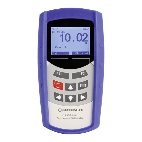
- Page 1 Englisch Operating Manual Water analysis – hand-held meter G 7500 series Companies / Brands of the GHM www.ghm-group.de Keep for later use.
-
Page 2: Table Of Contents
H87.0.0X.6C-01 Operating manual G 7500 Series page 2 of 34 Index 1 GENERAL NOTE ....................... 3 2 SAFETY ..........................3 2.1 I ........................3 NTENDED 2.2 S ......................3 AFETY GUIDELINES ...................... 3 QUALIFIED PERSONNEL 2.4 S .................... 4 AFETY SIGNS AND SYMBOLS 2.5 F... -
Page 3: General Note
H87.0.0X.6C-01 Operating manual G 7500 Series page 3 of 34 12.1 ........................ 32 ESHIPMENT 12.2 ........................32 ISPOSAL SPECIFICATION ......................33 13.1 ................. 33 MEASUREMENTS AND ACCURACY 13.2 ....................34 GENERAL SPECIFICATION TERMS OF LICENSE ....................34 14.1 RTOS ........................34 14.2... -
Page 4: Safety Signs And Symbols
H87.0.0X.6C-01 Operating manual G 7500 Series page 4 of 34 2.4 Safety signs and symbols The following signs in this document highlight warnings: Caution! This symbol warns of imminent danger, death, serious injuries and significant damage to property at non-observance. -
Page 5: Foreseeable Misuse
H87.0.0X.6C-01 Operating manual G 7500 Series page 5 of 34 2.5 Foreseeable misuse The fault-free function and operational safety of the product can only be guaranteed if generally applicable safety precautions and the device-specific safety instructions for this document are observed. - Page 6 H87.0.0X.6C-01 Operating manual G 7500 Series page 6 of 34 Do not use this product as safety or emergency stop devices or in any other application where failure of the product could result in personal injury or material damage. Failure to comply with these instructions could result in death or...
-
Page 7: Product Specification
H87.0.0X.6C-01 Operating manual G 7500 Series page 7 of 34 Product Specification 3.1 Scope of delivery The scope of supply includes: Device with 3 rechargeable batteries type AAA Short manual Operating manual and calibration protocol as pdf file in mass storage memory. -
Page 8: Support And Retaining Clip
H87.0.0X.6C-01 Operating manual G 7500 Series page 8 of 34 3.4 support and retaining clip The stand is provided as a means to prop up or support the device in a stable surface, for hanging on the wall or for attachment to a belt. -
Page 9: Operation
H87.0.0X.6C-01 Operating manual G 7500 Series page 9 of 34 4 Operation 4.1 Keypad With the keypad the device functions, display mode, etc. can be set by user interaction. The display will contain specific information for the F1 and F2 soft-keys. -
Page 10: Status Line
H87.0.0X.6C-01 Operating manual G 7500 Series page 10 of 34 4.2 Status line The status line is the first line in the display. Display Meaning Current time If time is flashing, time must be reseted Internal memory error. When this error won’t disappear after restarting the device, it should be returned for repairing. -
Page 11: Start Operation
H87.0.0X.6C-01 Operating manual G 7500 Series page 11 of 34 4.3.1 Menu Depending on the selected channel, you can switch to the channel configuration menu by pressing the function key F2. Here, channel-specific settings can be made. 5 Start operation Charge the rechargeable batteries by connecting a power supply or the computer to the micro USB connector. - Page 12 H87.0.0X.6C-01 Operating manual G 7500 Series page 12 of 34 6.1.1 Design 1. Coaxial cable 2. Reference electrode 3. Measuring electrode 4. Refill opening 5. Electrolyte 6. Internal buffer 7. Diaphragm 8. Glass membrane / source layer The diaphragm, which establishes a connection between the electrolyte and the liquid to be measured, can be designed in different ways.
- Page 13 H87.0.0X.6C-01 Operating manual G 7500 Series page 13 of 34 6.1.3 Further information pH electrode is a wear part. If the signal is very slow or the required values are no longer observed after careful cleaning and possible regeneration, the electrode must be replaced.
- Page 14 H87.0.0X.6C-01 Operating manual G 7500 Series page 14 of 34 6.1.5 Service life The service life of electrodes is normally at least 8 to 10 months. When cared for properly, this can usually increase to more than 2 years. The actual life will vary depending on the particular application.
-
Page 15: Basics About Conductivity
H87.0.0X.6C-01 Operating manual G 7500 Series page 15 of 34 6.2 Basics about conductivity Definition of conductivity �� The ability of a material to conduct electric current: �� = ��•�� length of the material diameter measured resistance �������������� ��... -
Page 16: Temperature Compensation
H87.0.0X.6C-01 Operating manual G 7500 Series page 16 of 34 6.5 Temperature compensation The conductivity of aqueous solutions depends on its temperature. The temperature dependency is strongly dependent on the type of solution. The temperature compensation recalculates solutions’ conductivity to a consistent reference temperature. -
Page 17: Design Of The Sensor Gwo 5610
H87.0.0X.6C-01 Operating manual G 7500 Series page 17 of 34 6.6 Design of the sensor GWO 5610 6.6.1 General The oxygen sensor is an active sensor. It consists of a platinum cathode, a lead anode and potassium hydroxide (KOH) as an electrolyte. If oxygen is present, it is reduced on the platinum cathode and the sensor delivers a signal. - Page 18 H87.0.0X.6C-01 Operating manual G 7500 Series page 18 of 34 Platinum electrode If oxygen is present, it is reduced on the platinum electrode and the sensor delivers a signal. Soiling on the platinum electrode or between the membrane and electrode can influence the measurement.
-
Page 19: Commissioning / Filling Of The Sensor Gwo 5610
H87.0.0X.6C-01 Operating manual G 7500 Series page 19 of 34 6.6.5 Measurement accuracy The measurement accuracy can be impaired by: ▪ An inadequate flow below the necessary value of approx. 30cm/sec. ▪ The water temperature and sensor temperature must be the same. The most accurate measurements are provided when the measuring temperature is calibrated. -
Page 20: Sensor Gwo 5610 Maintenance
H87.0.0X.6C-01 Operating manual G 7500 Series page 20 of 34 6.8 Sensor GWO 5610 maintenance After every calibration the sensor quality in % will be shown in the large digit display. When the quality is below 25 % the sensor should be maintained. -
Page 21: Basics About Oxygen Measuring
H87.0.0X.6C-01 Operating manual G 7500 Series page 21 of 34 6.9 Basics about oxygen measuring Please observe the following points when measuring dissolved oxygen: - For measuring remove the protective flask. - Do not disconnect electrode from device. If electrode has been disconnected, wait 2..3 hours till the final electrode signal has settled before carrying out measurements or a calibration. -
Page 22: Configuration
H87.0.0X.6C-01 Operating manual G 7500 Series page 22 of 34 7 Configuration There are various configuration parameters available depending on the product version and configuration. They can differ depending on the product version and configuration. In order to configure the product, you must first open the device settings menu. - Page 23 H87.0.0X.6C-01 Operating manual G 7500 Series page 23 of 34 active O2/cond. channels inactive active 7.1.1 time and date Here time and date can be set. The time is shown on the left in the upper status line. When the time blinks, the time is invalid.
- Page 24 H87.0.0X.6C-01 Operating manual G 7500 Series page 24 of 34 the channel is active and the alarm function is activated. The device will show ‘A’ in the status line, even if the alarm activity is off. 7.1.4 logger Three different functionalities can be set ...
-
Page 25: P Hchannel Menu
H87.0.0X.6C-01 Operating manual G 7500 Series page 25 of 34 7.2 pH channel menu <-- --> <-- measurement voltage Voltage (H) alarm function min.-limit max.-limit temp. compensation reference channel banana sockets O2/cond. electrode pH probe buffer GMH standard DIN standard... - Page 26 H87.0.0X.6C-01 Operating manual G 7500 Series page 26 of 34 7.2.3 buffer The buffers are auto detected. When the buffer is not recognized (no PHL or DIN buffer, very bad electrode, extreme temperature or contaminated buffer solution) the device will ask for manual input of pH value and temperature.
-
Page 27: Temperature Channel Menu
H87.0.0X.6C-01 Operating manual G 7500 Series page 27 of 34 7.3 temperature channel menu Independent available for both, temperature (O2/LF) and temperature (pH) sensortype NTC 10 k NTC 10 k only available for O2/LF Pt1000 unit °C °F alarm function min.-limit... -
Page 28: Conductivity Channel Menu
H87.0.0X.6C-01 Operating manual G 7500 Series page 28 of 34 7.5 conductivity channel menu measurement conductivity salinity alarm function min.-limit max.-limit cell factor auto-range range temp compensation linear lin. coefficient reference T=25 °C temperature T=20 °C 7.5.1 cell factor Manual input of the cell factor. G 7500 sets with conductivity electrode are preconfigured with the electrode’s cell factor. -
Page 29: Error Codes (In Dataset)
H87.0.0X.6C-01 Operating manual G 7500 Series page 29 of 34 8 Error codes (in dataset) While logging data or querying values via interface, the error codes will not be shown as human readable text. This is because the relation between error and error message would get lost between different languages. -
Page 30: Calibration
H87.0.0X.6C-01 Operating manual G 7500 Series page 30 of 34 9 Calibration 9.1 General information Each channel that supports a calibration will show cal. Above the F1-key. The Calibration will only be available when the logger is set to “not active”. -
Page 31: Calibration And Adjustment Service
H87.0.0X.6C-01 Operating manual G 7500 Series page 31 of 34 10 Calibration and adjustment service The certificates are categorised as ISO calibration certificates and DAkkS calibration certificates. The purpose of the calibration is to verify the precision of the measuring device by comparing it with a traceable reference. -
Page 32: Reshipment And Disposal
H87.0.0X.6C-01 Operating manual G 7500 Series page 32 of 34 Required tools: 1x Phillips screwdriver PH 1 Remove device from silicone cover. Unscrew 3 screws on the device bottom. Carefully open the top cover and fold to the right (see picture). The cover is attached to the PCB by a flexprint connector. -
Page 33: Specification
H87.0.0X.6C-01 Operating manual G 7500 Series page 33 of 34 13 Specification 13.1 measurements and accuracy suggested probe GE 125 (waterproof with Pt 1000 temperature probe) connector BNC-Buchse (waterproof) -2,00..+16,00 pH (+-0,25 % FS) -2 000..+2 000 mV (+-0,25 % FS) ORP (hydrogen referenced) -1 775..+2 148 mV (+-0,25 % FS) -
Page 34: General Specification
The copyright owner or contributors be NOT LIABLE for any damages caused by use of this software. GHM GROUP – Greisinger | GHM Messtechnik GmbH Hans-Sachs-Str. 26 | 93128 Regenstauf | GERMANY Phone +49 9402 9383-0 | Fax +49 9402 9383-33 www.greisinger.de...
Need help?
Do you have a question about the G 7500 Series and is the answer not in the manual?
Questions and answers