Table of Contents
Advertisement
Quick Links
Advertisement
Table of Contents

Subscribe to Our Youtube Channel
Related Manuals for GREISINGER G 7500


Summary of Contents for GREISINGER G 7500
- Page 1 Operating manual G 7500 Water analysis handheld measuring device...
-
Page 2: Table Of Contents
Qualified personnel.......................... 10 Description ............................ 11 Scope of delivery .......................... 11 Functional description......................... 11 The product at a glance ........................ 12 The G 7500............................ 12 Display elements .......................... 12 Operating elements .......................... 13 Connections............................ 13 Support stand ............................. 14 Bases for measurement ........................ 15 Suitable electrodes / sensors...................... - Page 3 Table of contents 5.7.1 Explanation ............................ 20 5.7.2 Design.............................. 21 5.7.3 Service life ............................ 21 5.7.4 Operating position.......................... 22 5.7.5 Measurement accuracy ........................ 22 5.7.6 Residue............................... 22 Commissioning, filling and maintenance of the sensor............... 22 Maintenance ............................ 24 Operating and maintenance notices .................... 24 Battery ..............................
-
Page 4: About This Documentation
1 | About this documentation G 7500 1 About this documentation 1.1 Foreword Read this document carefully and familiarise yourself with the operation of the product before you use it. Keep this document ready to hand and in the immediate vicinity of the product so that it is available to the personnel/user for reference at all times in case of doubt. -
Page 5: Fatfs
G 7500 About this documentation | 1 THE SOFTWARE IS PROVIDED 'AS-IS' WITHOUT ANY EXPRESS OR EXPLICIT GUARANTEE, INCLUDING BUT NOT LIMITED TO GUARANTEES OF COMMER- CIAL MARKETABILITY, SUITABILITY FOR A SPECIFIC PURPOSE AND NON-IN- FRINGEMENT ON THIRD-PARTY RIGHTS. UNDER NO CIRCUMSTANCES CAN... -
Page 6: Further Information
1 | About this documentation G 7500 Formula Some instructions include a formula for a general understanding of a configuration, programming or a setting of the product. Outcome of an action Result, consequence or effect of an instruction. Emphases In order to simplify legibility and provide a clearer overview, various sections / informa- tion are emphasised. -
Page 7: Safety
G 7500 Safety | 2 2 Safety 2.1 Explanation of safety symbols DANGER This symbol warns of imminent danger which can result in death, severe bodily injury, or severe property damage in case of non-observance. DANGER This symbol indicates danger for living tissue as well as a variety of materials, which can be damaged or destroyed when coming into contact with this chemical. -
Page 8: Foreseeable Misuse
2 | Safety G 7500 2.2 Foreseeable misuse The fault-free function and operational safety of the product can only be guaranteed if generally applicable safety precautions and the device-specific safety instructions for this document are observed. If these notices are disregarded, personal injury or death, as well as property damage can occur. - Page 9 G 7500 Safety | 2 DANGER Potassium hydroxide! The oxygen sensors contain potassium hydroxide. H290 can corrode metal. H314 causes severe caustic burns. All contact with the skin, clothing and eyes should be avoided. Nevertheless, should contact occur, take the following measures.
-
Page 10: Intended Use
2 | Safety G 7500 NOTE This product does not belong in children's hands! For this purpose, also refer to 2 Technical data [} 000] 2.4 Intended use Depending on the connected sensors, the device is intended exclusively for the follow- ing applications: –... -
Page 11: Description
G 7500 Description | 3 3 Description 3.1 Scope of delivery Please check to ensure the completeness of the product after opening the package. You should find the following components: – Quick reference guide – Handheld measuring device, ready for operation, including rechargeable batteries –... -
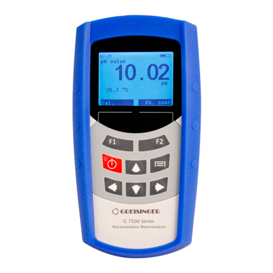
Page 12: The Product At A Glance
4 | The product at a glance G 7500 4 The product at a glance 4.1 The G 7500 Connection Display Operating elements G 7500 4.2 Display elements Display Status line The status line is the first line in the display. -
Page 13: Operating Elements
G 7500 The product at a glance | 4 4.3 Operating elements Function keys F1 and F2 Dark text is displayed directly above the buttons (e.g. 'Back' for F1 and 'Change' for F2) depending on the operating status, view, menu, channel, etc. -
Page 14: Support Stand
4 | The product at a glance G 7500 NOTE The temperature measurement can be influenced by conductive liquids on the banana sockets. We recommend always keeping the connections dry. 4.5 Support stand Description The stand is provided as a means to prop up or support the device in a stable surface, for hanging on the wall or for attachment to a belt. -
Page 15: Bases For Measurement
G 7500 Bases for measurement | 5 5 Bases for measurement 5.1 Suitable electrodes / sensors Measurement Suitable electrodes / sensors variable Conductivity LF 400, LF 425 Dissolved oxygen GWO 5610 Recommended: GE 125-BNC-L02 All other pH electrodes from our assortment are also compatible... -
Page 16: Design
5 | Bases for measurement G 7500 5.2.3 Design 1. Coaxial cable 2. Reference electrode 3. Measuring electrode 4. Refill opening 5. Electrolyte 6. Internal buffer 7. Diaphragm 8. Glass membrane / source layer Fig. 5: pH electrode The diaphragm, which establishes a connection between the electrolyte and the liquid to be measured, can be designed in different ways. -
Page 17: Choosing A Ph Electrode
G 7500 Bases for measurement | 5 5.2.6 Choosing a pH electrode The GE 114 WD or GE 100 can be used for most applications. However, some areas of application require special electrodes. – GE 100 BNC is a universal electrode with two ceramic diaphragms and liquid elec- trolyte. -
Page 18: Conductivity Principles
5 | Bases for measurement G 7500 Impurities Cleaners General residue Mild detergent Inorganic coatings Commercially available liquid glass clean- Metal compounds 1 mol/l HCl solution or GRL 100 pepsin cleaning solution Oil and grease Special cleaner or solvent Biological coatings with protein... -
Page 19: Calibration / Adjustment Of The Measuring Cell
G 7500 Bases for measurement | 5 2-pole measuring cell 4-pole measuring cell 5.5.2 Calibration / adjustment of the measuring cell In harsh applications and due to ageing processes, the cell constant of measuring cells changes. Depending on the application and precision requirement, the overall precision of the display device and measuring cell measuring chain should be checked regularly. -
Page 20: Oxygen Sensor
5 | Bases for measurement G 7500 5.7 Oxygen sensor 5.7.1 Explanation The oxygen sensor is an active sensor. It consists of a platinum cathode, a lead anode and potassium hydroxide (KOH) as an electrolyte. If oxygen is present, it is reduced on the platinum cathode and the sensor delivers a signal. -
Page 21: Design
G 7500 Bases for measurement | 5 5.7.2 Design Refill opening Shaft Membrane head Platinum electrode Storage bottle Platinum electrode If oxygen is present, it is reduced on the platinum electrode and the sensor delivers a signal. Soiling on the platinum electrode or between the membrane and electrode can influence the measurement. -
Page 22: Operating Position
5 | Bases for measurement G 7500 – Contamination of the measured water – Mechanical stress of the sensor membrane – Storage in dry air – Continuous use in elevated carbon dioxide concentrations 5.7.4 Operating position The oxygen sensor should be arranged vertically upwards with the connecting cable. - Page 23 G 7500 Bases for measurement | 5 Instruction 1. Unscrew the membrane head and wipe off the electrolyte solution with a paper towel. Do not touch the electrolyte with bare hands. If skin contact occurs, rinse off the affected area thoroughly with water.
-
Page 24: Maintenance
6 | Maintenance G 7500 6 Maintenance 6.1 Operating and maintenance notices NOTE If the product is stored at a temperature above 50 °C, or is not used for an extended period of time, the batteries must be removed or recharged regularly. This prevents leaks from the rechargeable batteries and increases the life of the rechargeable bat- teries. -
Page 25: Calibration And Adjustment
G 7500 Maintenance | 6 NOTE Read the following handling instructions before replacing batteries and follow them step by step. If disregarded, the product could be damaged or the protection from moisture could be diminished. Description Proceed as follows to replace the rechargeable batteries. -
Page 26: Ph Calibration
6 | Maintenance G 7500 Instruction Colour 10 °C 20 °C 25 °C 30 °C 40 °C GPH 4.0 Orange 3.99 3.99 4.01 4.01 4.03 GPH 7.0 Green 7.06 7.01 7.00 6.99 6.98 GPH 10.0 Blue 10.18 10.06 10.01 9.97 9.89... -
Page 27: O Calibration
G 7500 Maintenance | 6 6.3.3 O calibration Description In order to obtain reliable measurements, the device and measuring cell must be aligned with each other. In order to conduct a O calibration, proceed as follows. Prerequisite – The product is switched on –... -
Page 28: Operation
7 | Operation G 7500 7 Operation 7.1 Commissioning 7.1.1 Explanation Description The product is switched on with the On/Off button. It may be necessary to configure the product after switching on. See Configuration [} p. 28]. Prerequisite – The rechargeable batteries have been charged via the micro USB socket. -
Page 29: Device Settings
G 7500 Operation | 7 4. When you have chosen the desired parameter, you select it with function key F2. Then you can change it as necessary. 5. To save the change, press function key F2; press function key F1 to cancel. - Page 30 7 | Operation G 7500 7.2.3.2 USB mode 7.2.3.2.1 Mass storage unit If the mass storage unit USB mode is selected, the device can no longer access the internal buffer. Then the logger can no longer be started. You can access the buffer directly in this USB mode without a driver and copy the stored measurement data on the computer or delete the measurement data from the buffer.
- Page 31 G 7500 Operation | 7 No channel adjustments or calibrations can be carried out when the logger is running. The product can no longer be switched off with the On/Off button. Instead, the Device settings menu is displayed. Not activated. The setting can be changed here. The log- ger can be started with function key F1 and Start appears in the display.
-
Page 32: Call-Up Of Channel Settings
7 | Operation G 7500 – The channel is active – The alarm is activated in the channel menu The letter A appears in the status line. This indicates that all requirements are fulfilled. This also applies with Alarm action off. - Page 33 G 7500 Operation | 7 7.2.5.1.1 Measurement type Voltage Voltage (H) 7.2.5.1.2 Alarm Function – Off – On Min. limit – -2.00 to 16.00 pH Max. limit – -2.00 to 16.00 pH 7.2.5.1.3 Temperature compensation Automatic temperature compensation can be switched on or off. The temperature can be entered manually when it is switched off.
- Page 34 7 | Operation G 7500 With the manual query after calibration and use of standard buffers listed below, the sensor quality must be checked and, if necessary, a new buffer must be used, the electrodes must be cleaned and maintained or the electrode must be replaced. If the buffers are exposed to very high or low temperatures, wait until they have settled to room temperature 20 ..
- Page 35 G 7500 Operation | 7 NTC 10 K Pt 1000 7.2.5.2.2 Unit °C °F 7.2.5.2.3 Alarm Function – Off – On Min. limit – When the adjusted min. limit is undercut, the selected alarm action is triggered. Max. limit – When the adjusted max. limit is exceeded, the selected alarm action is triggered.
- Page 36 7 | Operation G 7500 Min. limit – When the adjusted min. limit is undercut, the selected alarm action is triggered. Max. limit – When the adjusted max. limit is exceeded, the selected alarm action is triggered. 7.2.5.3.3 Salinity Input of the salinity compensation. With values not equal to 0, the measured oxygen value is converted based on the adjusted salinity.
- Page 37 G 7500 Operation | 7 7.2.5.4.3 Cell constant Input of the cell constant. With a G 7500 set with, e.g. a conductivity measuring cell, this value is pre-adjusted and does not have to be entered manually. NOTE If the sensor is changed, the new value must be entered.
-
Page 38: Error And System Messages
8 | Error and system messages G 7500 8 Error and system messages The error codes are not displayed as text in the data recording and with query via the interface. This is due to the fact that reference would no longer be made to the actual error with different languages. - Page 39 G 7500 Error and system messages | 8 Not found Restart the product -101 Not calibrated Product has not Perform calibration been calibrated yet -253 Value unstable Measurement or Provide a stable environ- temperature fluctu- ment ations -251 Out of temperature...
-
Page 40: Disposal
9 | Disposal G 7500 9 Disposal Separation by material and recycling of device components and packaging must take place at the time of disposal. The valid regional statutory regulations and directives applicable at the time must be observed. NOTE The device must not be disposed of with household waste. -
Page 41: Technical Data
G 7500 Technical data | 10 10 Technical data Measuring types and ac- curacy Recommended electrode GE 125 (waterproof with Pt1000 temperature sensor) Connection BNC socket (waterproof) -2.00 .. +16.00 pH (± 0.25 % FS) Redox -2 000 .. +2 000 mV (± 0.25 % FS) Redox (hydrogen reference) -1 775 .. - Page 42 10 | Technical data G 7500 Data logger On internal mass storage unit (2018 or later: 8 GB) Display Monochromatic 180 x 128 px LC display (white and red backlighting) Primary power supply 3x AAA NiMH rechargeable batteries (750 mAh) Current requirement approx.
-
Page 43: Spare Parts And Accessories
G 7500 Spare parts and accessories | 11 11 Spare parts and accessories A selection of spare parts and accessories for this product is listed below. Article Number Name Description 410355 NiMH re- NiMH replacement rechargeable battery chargeable bat- tery... -
Page 44: Service
12 Service 12.1 Manufacturer If you have any questions, please do not hesitate to contact us: Contact GHM Messtechnik GmbH GHM GROUP - Greisinger Hans-Sachs-Str. 26 93128 Regenstauf | GERMANY Email: info@greisinger.de | www.greisinger.de WEEE reg. no. DE 93889386 12.2 Repairs processing Defective products are repaired professionally and quickly in our service centre. -
Page 45: Sales Subsidiaries
Phone +33 4 72 37 45 30 Phone +91 22 40236235 info@ghm.dk | www.ghm.dk a.jouanilou@ghm-group.fr info@ghmgroup.in | www.ghmgroup.in Italy for Greisinger & Delta OHM Italy for Honsberg, Martens, Val.co Netherlands GHM GROUP – Delta OHM GHM GROUP – Val.co GHM Meettechniek BV...
Need help?
Do you have a question about the G 7500 and is the answer not in the manual?
Questions and answers