
Related Manuals for Festo CMMB-AS-0x


Summary of Contents for Festo CMMB-AS-0x
- Page 1 Motor controller CMMB-AS-0x Description Mounting and installation For motor controller CMMB-AS-0x 8068718 2017-07a [8068715] Festo CMMB-AS servo manual...
- Page 2 Text designations: Activities that may be carried out in any order 1. Activities that should be carried out in the order stated General lists – Result of an action / references to more detailed information Festo CMMB-AS servo manual...
- Page 3 Revisions history Version Chapter Date Change 1.00 2017-03-17 First release 1.01 3.2.4, 6.2.1, 6.3.1 2017-05-09 Figure 3-5, tables 6-7, 6-11 1.02 3.1.1, 3.2.2 2017-07-18 Table 3-1, Table 3-2 Festo CMMB-AS servo manual...
-
Page 4: Table Of Contents
3.2.5 Encoder input(X5) ...................... 12 3.3 Wiring of the CMMB servo system ..................12 3.3.1 Selection of fuses, braking resistors and circuit breakers ..........13 Chapter 4 Controller setup with LED panel ..............14 4.1 Panel operation........................14 Festo CMMB-AS servo manual... - Page 5 4.2 Panel menu structure and navigation ..................15 4.3 Easy Use function ......................... 16 4.3.1 Setup process with Easy Use function ................16 4.3.2 Flowchart and description of the EASY menu ..............17 4.3.3 Flowchart and description of the tunE menu ..............23 4.3.4 Jog mode (F006) ......................
- Page 6 6.4.1 Position Table mode ....................... 50 6.5 Pulse Train mode (-4)......................54 6.5.1 Master-slave mode ......................55 6.6 Homing mode (6) ......................... 55 Chapter 7 Tuning of the servo system control ..............65 7.1 Auto-tuning .......................... 65 7.1.1 Parameters for auto-tuning ..................... 66 7.1.2 Start of auto-tuning ......................
-
Page 7: Chapter 1 Safety And Requirements For Product Use
Chapter 1 Safety and requirements for product use 1.1 Safety 1.1.1 Safety instructions for commissioning, repair and de-commissioning Warning Danger of electric shock If cables are not mounted to the plug X2. – If connecting cables are disconnected when energised. –... -
Page 8: Intended Use
Use in control cabinets for power supply to AC servo motors and regulation of torques (current), rotational speed and position. The CMMB-AS-0x is intended for installation in machines or automated systems and may only be used: – When in excellent technical condition –... -
Page 9: Qualification Of The Specialists (Requirements For Personnel)
– 1.2.4 Range of application and certifications Certificates and declaration of conformity for this product can be found at www.festo.com/sp. The product has been certified by Underwriters Laboratories Inc. (UL) for the USA and Canada and is marked as follows:... -
Page 10: Emmb Servo Motor
2.1.2 EMMB Servo motor The EMMB series of high performance AC servo motors includes motors within a range of 100 to 750W rated power and is a equipped with 20 bit single-turn absolute encoder feedback systems. Figure 2-2: Servo motor type code 2.1.3 NEBM cables NEBM cables provide plug and play connectivity between the motor controller and the servo motors, and are available in four different standard lengths. - Page 11 Table 2-3: Encoder cable Standard cable Length (unit: m) Type NEBM-REG6-K-2.5-Q14N-REG6 NEBM-REG6-K-5-Q14N-REG6 NEBM-REG6-K-7.5-Q14N-REG6 NEBM-REG6-K-10-Q14N-REG6 Flexible cable (usable in cable chain) Length (unit: m) Type NEBM-REG6-E-2.5-Q14N-REG6 NEBM-REG6-E-5-Q14N-REG6 NEBM-REG6-E-7.5-Q14N-REG6 NEBM-REG6-E-10-Q14N-REG6 Table 2-4: Brake cable Standard cable Length (unit: m) Type NEBM-H7G2-K-2.5-Q14N-LE2 NEBM-H7G2-K-5-Q14N-LE2 NEBM-H7G2-K-7.5-Q14N-LE2 NEBM-H7G2- K-10-Q14N-LE2 Flexible cable (usable in cable chain)
-
Page 12: Device View
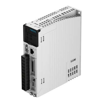
2.2 Device view Figure 2-3: Device view... -
Page 13: Installation Of The Cmmb Motor Controller
Chapter 3 Installation of the CMMB motor controller 3.1 Mechanical installation 3.1.1 Environment requirements Table 3-1: Environment requirements Environment Requirement 0 - 40℃ (no ice) Working temperature Working humidity 5 - 95%RH (no condensation) -10 - 70℃ (no ice) Storage temperature Storage humidity 5 - 95%RH (no condensation) Assembly requirement... -
Page 14: Electrical Installation
Note The motor controller has to be installed in an electrical cabinet which provides a pollution degree 2 environment. The installation is vertical to provide sufficient convection air flow through the orientation controller housing. Comply with distances and clearances shown in figure 3-1. Ensure that the motor controller is securely mounted with two M5 screws. -
Page 15: Power Connector (X2)
3.2.2 Power connector (X2) Table 3-2: Power connector Function Control power input L/N Single phase 200 – 240VAC ±10% 50 / 60Hz, 0.5A Supply earthing systems: TN-S, TN-C, TN-C-S, TT (not corner earthed). Drive power input L/N Single phase 200 – 240VAC ±10%, 50 / 60Hz 750W @7A, 400W @4.5A, 200W @3A, 100W @1.5A DC+/RB1 Supply earthing systems: TN-S, TN-C, TN-C-S, TT (not corner earthed). -
Page 16: Multi-Function Connector(X4
3.2.4 Multi-function connector(X4) AIN1+ AIN1- AIN2+ AIN2- OUT5 ENCO_Z ENCO_/Z ENCO_B ENCO_/B ENCO_A ENCO_/A OUT1+ OUT1- OUT2+ OUT2- OUT3 OUT4 COMO COMI DIN1 DIN2 DIN3 DIN4 DIN5 DIN6 DIN7 Figure 3-3: Multi-function connector Table 3-4: Definition of X4 Function Digital signal input VinH (active): 12.5VDC-30VDC, DIN1-DIN7 VinL (inactive): 0VDC-5VDC,... - Page 17 The following figure shows the wiring of X4 with default IO function. More IO functions can be defined with the digital panel or PC software. Please refer to chapter 5.5 for more details regarding IO functions. Enable Ready DIN1 OUT1+ Reset Errors DIN2 OUT1-...
-
Page 18: Encoder Input(X5
3.2.5 Encoder input(X5) Table 3-5: Encoder input Pin number Definition Function 5VDC power supply for encoder Signal ground (+5 V) Serial data signal Serial data signal Other Reserved 3.3 Wiring of the CMMB servo system Figure 3-7: Wiring of the CMMB servo system Warning Danger of electric shock Before conducting any installation or maintenance work on the CMMB controller, switch... -
Page 19: Selection Of Fuses, Braking Resistors And Circuit Breakers
Warning Danger of electric shock The CMMB motor controller uses mains voltage for logic supply power. Even when supply power to the controller is switched off and the DC bus is discharged (charge lamp at front is off), the control power input X2: L1C/L2C may still have active mains voltage. If the LED at the front of the motor controller is on, mains voltage must be expected at X2: L1C/L2C. -
Page 20: Chapter 4 Controller Setup With Led Panel
Chapter 4 Controller setup with LED panel After the servo system has been wired properly and in accordance with relevant standards, the motor controller can be setup for the desired application. The CMMB motor controller provides an LED panel at the front panel. It consists of a 5-digit LED display and four buttons. -
Page 21: Panel Menu Structure And Navigation
Enter menu. Check the values of the parameters. Confirm the setting to access the next step. When the internal 32 bit data appears at the display, press and hold to switch high / low 16 bit. Error or warning status. Lit up for 1s and dark for 1s indicates a controller error. Continuous flashing (3 Overall flash consecutive rapid flashes) indicates that the controller is in a warning state. -
Page 22: Easy Use Function
4.3 Easy Use function The Easy Use function helps users setup the CMMB motor controller for the main types of applications in a very short time. The LED panel guides the userstep by step through the settings of the few most important parameters in order to prepare the controller for the desired application. -
Page 23: Flowchart And Description Of The Easy Menu
4.3.2 Flowchart and description of the EASY menu The following flowchart and table explain the procedure for settings in the EASY menu in detail. Figure 4-3: Flowchart of the EASY menu Information The menu is exited automatically if there is no operation in 30s, and users have to start again. - Page 24 Table 4-2: EASY menu parameters Parameter Description Default For a new motor controller, the set motor type is “00” and “3030” appears at the LED display. If the new motor controller is connected to a valid motor, the motor type is auto-recognized and saved. The motor type saved in the controller and the connected motor type are compared later on.
- Page 25 0: Normally closed contacts 1: Normally open contacts EA07 Homing method Refer to chapter 6.6 Write “1” to save control and motor parameters. Write “2” to save control and motor parameters and reboot the servo. Write “3” to reboot the servo. Write “10”...
- Page 26 Note Be aware of the different (default) setting of the digital I/O configuration after setting the command type in EA02 or changing a motor type. When settings are changed, an active function may be assigned to digital inputs which have not been in use before as a result of the new defaults, and signals applied to the digital inputs may inadvertently trigger DIN functions.
- Page 27 Analog control mode configuration, command types 6 or 7 in EA02: Enable Ready DIN1 OUT1+ Reset Errors DIN2 OUT1- Start Homing Motor Brake DIN3 OUT2+ P limit+ DIN4 OUT2- Digital Digital P limit- Velocity Reached Input Output DIN5 OUT3 Zero Speed DIN6 OUT4 Home Signal...
- Page 28 RS232 control mode, command type 8 in EA02: Ready DIN1 OUT1+ DIN2 OUT1- Motor Brake DIN3 OUT2+ P limit+ DIN4 OUT2- Digital Digital P limit- Pos Reached Input Output DIN5 OUT3 Zero Speed DIN6 OUT4 Home Signal Error DIN7 OUT5 Input Common Output Common COMI...
-
Page 29: Flowchart And Description Of The Tune Menu
4.3.3 Flowchart and description of the tunE menu The tunE panel menu includes parameters and functions for auto-tuning with inertia measurement and servo control loop adjustment via just one parameter, namely stiffness. After processing the EASY menu, the controller defaults the stiffness value and the inertia_ratio based on reasonable estimated values according to, load type and application settings in EA06. - Page 30 Table 4-4: tunE parameters Parameter Description Default Level of control stiffness from 0 to31 determines the bandwidth (BW) of the velocity loop and the position loop (see table 4-5). The larger the value, the greater the stiffness. If this parameter is too large, gain will change Belt: 10 tn01 Stiffness...
- Page 31 The auto-tuning algorithm uses the following table of control loop bandwidth settings in relation to the stiffness value: Table 4-5: Stiffness and control loop settings Output filter Output filter Stiffness Kpp/[0.01Hz] Kvp/[0.1Hz] Stiffness Kpp/[0.01Hz] Kvp/[0.1Hz] [Hz] [Hz] 1945 2223 2500 2778 1000 3334...
-
Page 32: Jog Mode (F006)
4.3.4 Jog mode (F006) The Jog mode is intended to be used for a motor test run by the buttons of the LED panel without the need for any other command signal. No matter other Operation_Mode and velocity settings, in the Jog mode the controller controls the motor rotating with the velocity set by Jog_RPM(d3.52) in instantaneous velocity mode (Operation_Mode=-3, refered to chapter 6.1). -
Page 33: Chapter 5 Cmmb Configurator, User Guide
Chapter 5 CMMB configurator, user guide This chapter contains information about how to use the PC software CMMB Configurator. Figure 5-1: Main window of CMMB Configurator 5.1 Getting started 5.1.1 Language Language can be switched between English and Chinese via menu item Tools->Language. 5.1.2 Opening and saving project files Create a new project file via menu item File->New, or by clicking the button. -
Page 34: Starting Communication
5.1.3 Starting communication Click menu item Communication->Communication settings. The following window appears: Figure 5-2: Communication settings Select the right COM port (if it’s not shown click the “Refresh” button), baud rate and COM ID (Node ID), and then click the "OPEN” button. Once communication has been established with the controller, communication can be opened or closed by clicking the button. -
Page 35: Init Save Reboot
Click Add and double click the required object from the Object Dictionary. The selected object is then added to the list. Click Delete. The selected object is removed from the list. Click Help to read a description of the selected object in the Object Dictionary. 5.2 Init save reboot Click Controller->Init Save Reboot. -
Page 36: Read/Write Controller Configuration
Click Load File to select the firmware file (.servo) and then click Download to start loading firmware to the controller. Information Do not switch off the power or disconnect the RS232 cable during firmware loading. If the download process is interrupted, first reset controller power. Then select the firmware file and click the Download button, and finally start RS232 communication. -
Page 37: Digital Io Functions
Figure 5-7: Transfer settings Click Open File to select a parameter settings file (.cdi). The parameter settings appear in the window. The .cdi file contains information including object address, object value and readout result. If readout result is “False”, “Invalid” will appear immediately in red ion the Result fied. Click Write to Controller to get the Check Value and Result. -
Page 38: Digital Inputs
5.5.1 Digital inputs The CMMB motor controller provides 7 digital inputs. The functions of these digital inputs can be configured. Functions can be set via factory defaults or application default settings after processing the Easy setup menu ( see chapter 4). The functions of the digital inputs can also be freely configured. Figure 5-9: Digital Input Function: Click to select DIN function setting, click... - Page 39 The following table lists the digital input functions: Table 5-2: Digital input functions DIN Function Description Controller enabling Enable 1: Enable controller (Controlword=Din_Controlword(2020.0F) , default value=0x2F) 0: Disable controller (Controlword = 0x06) Reset Errors Sets the Controlword to reset errors, active edge: 0 -> 1 Operation_Mode selection Operation Mode sel 1: Operation_Mode=EL.Din_Mode1 (2020.0E), default value = -3...
-
Page 40: Digital Outputs
5.5.2 Digital outputs The CMMB motor controller provides 5 digital outputs. The functions of these digital outputs can be configured. Functions can be set via factory defaults or application default settings after processing the Easy setup menu (see chapter 4). The functions of the digital outputs can also be freely configured also. Figure 5-10: Digital output Function: Click to select the OUT function setting. -
Page 41: Gear Ratio Switch (Expert Only)
The following table lists the digital output functions: Table 5-3: Digital output functions OUT Function Description Ready Controller is ready to be enabled Error Controller error Under position mode, position difference between Pos_Actual and Pos Reached Pos_Target<Target_Pos_Window(6067.00),duration>=Position_Window_time(6068.00) |Speed_1ms(60F9.1A)|<=Zero_Speed_Window(2010.18) and Zero Speed duration >=Zero_Speed_Time(60F9.14) Signal for controlling the motor brake. -
Page 42: Gain Switch (Expert Only)
2509.06 Uint16 Gear_Divider[3] 2509.07 Int16 Gear_Factor[4] 2509.08 Uint16 Gear_Divider[4] 2509.09 Int16 Gear_Factor[5] 2509.0A Uint16 Gear_Divider[5] 2509.0B Int16 Gear_Factor[6] 2509.0C Uint16 Gear_Divider[6] 2509.0D Int16 Gear_Factor[7] 2509.0E Uint16 Gear_Divider[7] The actual gear ratio is Gear_Factor[x], Gear_Divider[x], whereas x is the BCD code of bit 0: Multifunction0 bit 1: Multifunction1 bit 2: Multifunction2... - Page 43 2340.05 Uint16 Kvi[1] 2340.06 Int16 Kpp[1] Dec. Hz 2340.07 Uint16 Kvp[2] Dec, Hz 2340.08 Uint16 Kvi[2] 2340.09 Int16 Kpp[2] Dec. Hz 2340.0A Uint16 Kvp[3] Dec, Hz 2340.0B Uint16 Kvi[3] 2340.0C Int16 Kpp[3] Dec. Hz 60F9.28 Uint8 PI_Pointer 60F9.09 Uint8 PI_Switch The actual PI settings are Kvp[x], Kvi[x], Kpp[x], x=PI_Pointer.
-
Page 44: Fast Capture
5.5.5 Fast Capture The Fast Capture function is used to capture the Position_Actual(6063.00) when the related DIN edge occurs. Response time is maximum 2ms. Table 5-6: Fast capture objects Internal address Type Name Value Unit 2010.20 Uint8 Rising_Captured1 2010.21 Uint8 Falling_Captured1 2010.22 Uint8... -
Page 45: Scope
5.6 Scope The scope function is for sampling the selected objects’ value with a flexible sample cycle (defined by Sample Time) and a flexible total sample number (defined by Samples) During operation, if performance does not meet the requirement or any other unexpected behaviour occurs, it’s highly advisable to use the scope function to do the analysis. -
Page 46: Error Display And Error History
Figure 5-14: Cusor data Export: Exports the sampled data as a .scope file. Import: Imports a .scope file and shows the oscillogram in the scope window. Reread: Rereads the last scope data out of the controller and shows the oscillogram in the scope window. Auto: If the checkbox Auto is checked, the oscillogram is auto-scaled. - Page 47 Temperature Overvoltage 0x3210 DC bus overvoltage Undervoltage 0x3220 DC bus undervoltage Overcurrent 0x2320 Power stage or motor short circuit Chop Resistor 0x7110 Overload, brake chopper resistor Following Error 0x8611 Max. following error exceeded Low Logic Voltage 0x5112 Logic supply voltage too low Motor or controller IIt 0x2350 Motor or power stage IIt error...
- Page 48 Information There’s a mask checkbox beside every error item, all are defaulted to be checked, means it can be unchecked, means it can’t be unchecked. An unchecked item mean the related error will be ignored. The error mask can be set in Error_Mask(2605.01) and Error_Mask(2605.04) also (see table 5-9) Error History: Click menu item Controller->Error History.
-
Page 49: Operation Modes And Control Modes
Chapter 6 Operation modes and control modes Controller parameters can be set via the control panel or the RS232 port (e.g. with CMMB Configurator software). In the following introduction, both the panel address (if it’s available) and the internal address will be shown in the object tables. - Page 50 Table 6-2: Digital output function Panel address Internal address Type Name Value (hex): description 0001: Ready d3.11 2010.0F Uint16 Dout1_Function 0002: Error 0004: Pos Reached 0008: Zero Speed d3.12 2010.10 Uint16 Dout2_Function 0010: Motor Brake 0020: Speed Reached d3.13 2010.11 Uint16 Dout3_Function 0040: Enc Index...
- Page 51 Table 6-5: Common parameters Panel Internal Type Name Description address address 6083.00 Uint32 Profile_Acc Profile acceleration, profile deceleration, for Operation_Mode 1 and 3 6084.00 Uint32 Profile_Dec d2.24 6080.00 Uint16 Max_Speed_RPM Maximal speed (unit: rpm) d3.16 2020.0D Int8 Din_Mode0 If Operation Mode Sel function is configured to DIN, Operation_Mode(6060.00)=Din_Mode0 when Din_Internal=0;...
-
Page 52: Velocity Mode (-3, 3)
6.2 Velocity mode (-3, 3) There are 2 kinds of velocity mode: -3 and 3. The velocity command can be specified via Target_Speed or analog input (analog speed mode), or via digital input (DIN speed mode). Table 6-6: Velocity mode Panel Internal Type... - Page 53 Default is 0, if it’s NOT 0, 2502.0D Int16 Analog_Dead_High Analog_out>Analog_Dead_High is treated as 0 User defined Default is 0, if it’s NOT 0, 2502.0E Int16 Analog_Dead_Low Analog_out<Analog_Dead_Low is treated as 0 d3.33 2FF0.22 Int16 Voltage_MaxT_Factor AIN-MaxTorque factor (unit: mNM/V) User defined 0: Analog_MaxTorque control OFF d3.32...
-
Page 54: Din Speed Mode
6.2.2 DIN speed mode The Din_Speed object window in PC software can be accessed from menu item Controller->Control Modes->DIN Speed Mode. To make the DIN Speed Mode available, at least one of the following has to be configured to DIN: Din Vel Index0, Din Vel Index1, Din Vel Index2. -
Page 55: Torque Mode (4)
6.3 Torque mode (4) In the torque mode, the CMMB motor controller causes the motor to rotate with a specified torque value. Table 6-10: Torque mode Panel Internal Type Name Description Value address address 6060.00 Int8 Operation_Mode Target torque, 6071.00 Int16 Target_Torque% User defined... -
Page 56: Position Mode (1)
(6071.00) 1: Torque control via AIN1 2: Torque control via AIN2 d3.33 2FF0.22 Int16 Voltage_MaxT_Factor AIN-MaxTorque factor (unit: mNM/V) User defined 0: Analog_MaxTorque control OFF d3.32 2502.09 Uint8 Analog_MaxT_Con 1: max. torque control via AIN1; 0, 1, 2 2: max. torque control via AIN2 For convenience, some new names are used in the formula. - Page 57 Table 6-13: Din functions of the position table mode Name Description PosTable Cond0 If Cond0 ON, Condition0 = PosTable Cond0 (refer to introduction concerning Cond0 ON) PosTable Cond1 If Cond1 ON, Condition1 = PosTable Cond1 (refer to introduction concerning Cond1 ON) Start PosTable Start position flow PosTable Idx0...
- Page 58 The DIN Start PosTable signal (rising edge) triggers the entry index (specified via the DIN function) task, but whether or not the task is executed depends on the start condition (CTL reg bit14-15). After one task is finished, it goes to the next index (CTL reg bit0-4) or stops, depending on Next / Stop (CTL reg bit 8), Condition (CTL reg bit 9-11) and Loops.
- Page 59 Bits 14-15: StartCond, start condition. If this task is triggered by the Start PosTable signal, normally the controller will execute it immediately, but if there’s a positioning task still running: 0 (ignore): ignore. 1 (wait): execute this command after current task is finished (without delay). 2 (interrupt): interrupt the current task, execute this command immediately.
-
Page 60: Pulse Train Mode (-4)
6.5 Pulse Train mode (-4) In the pulse mode, the target velocity command is specified via the pulse input with gear ratio. Table 6-15: Pulse mode Panel Internal Type Name Description Value address address 6060.00 Int8 Operation_Mode d3.34 2508.01 Int16 Gear_Factor[0] Gear_ratio=Gear_Factor/Gear_Divider User defined... -
Page 61: Master-Slave Mode
PD_filter effect principle: Position Command Command After Filter Px0.707 Command Before Filter Px0.293 Time Filter Time Filter Time Figure 6-6: Pulse filter principle 6.5.1 Master-slave mode The master-slave mode is a type of pulse train mode – PD_CW = 2. The pulse input for the slave controller comes from an external incremental encoder or the encoder output of the master controller. - Page 62 Click menu item Controller->Control Modes->Homing definition, and the following window appears: Figure 6-8: Homing settings Select a home trigger under Homing Trigger. The related items appear in the configuration area. Select a suitable item according to mechanical design and wiring. The Appropriate homing_method then appears in the Pre-Set Home Method box.
- Page 63 1: Start homing after power on or reboot 6099.03 Uint8 Homing_Power_On 0, 1 and first controller enable Profile deceleration acceleration 609A.00 Uint32 Homing_Accelaration during homing User defined 6099.04 Int16 Homing_Current Max. current during homing 0: Go to the homing offset point. The actual position will be 0.
- Page 64 Homing with positive position limit switch and index pulse Homing with home switch and index pulse Homing with home switch and index pulse Homing with home switch and index pulse...
- Page 65 Homing with home switch and index pulse Homing with positive position limit switch, home switch and index pulse Homing with positive position limit switch, home switch and index pulse Homing with positive position limit switch, home switch and index pulse...
- Page 66 Homing with positive position limit switch, home switch and index pulse Homing with negative position limit switch, home switch and index pulse Homing with negative position limit switch, home switch and index pulse Homing with negative position limit switch, home switch and index pulse Homing with negative position limit switch, home switch and...
- Page 67 Homing with negative position limit switch Homing with positive position limit switch Homing with home switch Homing with home switch...
- Page 68 Homing with home switch Homing with home switch Homing with positive position limit switch and home switch Homing with positive position limit switch and home switch Homing with positive position limit switch and home switch...
- Page 69 Homing with positive position limit switch and home switch Homing with negative position limit switch and home switch Homing with negative position limit switch and home switch Homing with negative position limit switch and home switch Homing with negative position limit switch and home switch...
- Page 70 33, 34 Homing with index pulse Homing to actual position -17, -18 Homing via mechanical limit...
-
Page 71: Chapter 7 Tuning Of The Servo System Control
Chapter 7 Tuning of the servo system control Profile generator Acceleration feedforward Kaff POWER Torque demand Speed demand analog1 analog1 i-limit analog2 analog2 Profile speed DCBUS+ Average filter Kvff Current Notch filter feedback ∫ 1 order Lowpas 2 order DCBUS- filter Real speed Profile position... -
Page 72: Parameters For Auto-Tuning
Caution: auto-tuning causes the motor to oscillate for about 1 second and the maximum oscillation range is roughly 0.5 rev: make sure that your machine system can withstand this oscillation. 7.1.1 Parameters for auto-tuning Table 7-1: Auto-tuning function parameters R: read Panel Internal Name... -
Page 73: Problems With Auto-Tuning
increase Safe_Dist(3040.06) to get more precise results. If the machine shakes too much, reduce_Safe_Dist to reduce oscillation. 7.1.3 Problems with auto-tuning If the tuning process has failed, the error result of tn03 / Inertia_Get_Result(3040.09) tells the fail-reason: The controller could not be enabled by any reason. Inertia cannot be measured due to too little motion or too little current. -
Page 74: Manual Tuning
7500 2700 1765 8612 3100 1765 9445 3400 ∞ 1056 10278 3700 ∞ 1250 11112 4000 ∞ 1500 12500 4500 ∞ 1667 13889 5000 ∞ Stiffness should be adjusted according to the actual requirement. If response is too slow increase stiffness. If oscillation or noise increases reduce stiffness. If the command from the controller (e.g. - Page 75 Table 7-3: List of velocity loop parameters Panel Internal Name Description Default Range address address Proportional velocity loop gain 60F901 Kvp[0] Can be displayed in Hz in the PC tool can if the 1-32767 inertia ratio is right. Changing this parameter changes kvp[0] by the d2.01 2FF00A Velocity_BW...
-
Page 76: Tuning Of The Position Loop
Output filter adjustment The output filter is a 1 order torque filter. It can reduce the velocity control loop to output high frequency torque, which may stimulate overall system resonance. The user can try to adjust Output_Filter_N from small to large in order to reduce noise. The filter bandwidth can be calculated using the following formula. - Page 77 Max_Following_ Maximum allowable error, Max_Following_Error d2.25 2FF0.0E 5242 Error_16 (6065.00) = 100 * Max_Following_Error_16 Position loop proportional gain adjustment Increasing position loop proportional gain can improve position loop bandwidth, thus reducing positioning time and following error, but setting it too high will cause noise or even oscillation. It must be set according to load conditions.
-
Page 78: Factors Which Influence Tuning Results
The smoothing filter can reduce machine impact by smoothing the command. The Pos_Filter_N parameter define the time constant of this filter in ms. Normally, if the machine system oscillates when it starts and stops, a larger Pos_Filter_N is suggested. Notch filter The notch filter can suppress resonance by reducing gain around the resonant frequency. -
Page 79: Alarms And Troubleshooting
Chapter 8 Alarms and troubleshooting Alarm code numbers flash at the panel when the controller generates an alarm. If you need more detailed information about errors and error history, please connect the controller to the PC via RS232 and refer to chapter 5.7. Table 8-1: Alarm codes of Error_State1 Alarm Name... - Page 80 Machine equipment stuck or excessive is enabled. friction. Eliminate the problem of mechanical sticking, Duty cycle of motor overload exceeds the add lubricate. motor rated performance Reduce the acceleration or load inertia. Reduce pulse frequency. Over 100.0 External input pulse frequency is too high. Increase the value of Frequency_Check frequency (d3.38).
-
Page 81: Chapter 9 List Of Cmmb Series Motor Controller Parameters
Chapter 9 List of CMMB series motor controller parameters 9.1 F001 This panel menu contains all controller values which can be shown by the LED display when it’s in the monitor mode (see 4.2) and no error or warning is shown. On the LED panel, select the panel address of the value to be displayed and press SET. -
Page 82: F002
d1.17 60410010 Status word Status word of controller d1.18 60610008 Operation_Mode_Buff Operation mode in buffer -2^31- d1.19 60630020 Pos_Actual Actual position of motor 2^31-1 -2^31- d1.20 60FB0820 Pos_Error Following error of position 2^31-1 Input pulse amount before electronic -2^31- d1.21 25080420 Gear_Master gear... - Page 83 BW=Speed_Fb_N*20+100[Hz] Default: 0, means using 2 order low pass filter 0: 2 order FB LPF 1: No FB LPF 2: Observer FB d2.06 60F90608 Speed_Mode 0-255 4: 1st order FB LPF 10: 2nd LPF+SPD_CMD FT 11: SPD_CMD FT 12: SPD_CMD FT+Observer 14: 1st LPF+Observer d2.07 60FB0110...
-
Page 84: F003
9.3 F003 This panel menu contains parameter for the configuration of analog and digital I/O functions. Controller->Panel Menu->F003 DI/DO & Operation Mode Setting(F003) Table 9-3: Panel F003 parameters Panel Internal Name Description Default Range address address Save or init parameters d3.00 2FF00108 Store_Data... - Page 85 -1000- d3.26 2FF01F10 Analog2_Dead_V Unit: 0.01V 1000 -1000- d3.27 2FF02010 Analog2_Offset_V Unit: 0.01V 1000 Analog signal controls velocity, valid in operation mode 3 or -3 0: analog speed control OFF, velocity d3.28 25020708 Analog_Speed_Con 0-255 control via Target_Speed(60FF.00) 1: velocity controlled by AIN1 2: velocity controlled by AIN2 Analog speed factor -32768-...
- Page 86 Configure the filter in the CPLD. For 50% duty cycle signal: 0: 125ns 1: 156ns 2: 250ns d3.49 30460008 CPLD_Filter 3: 313ns 4: 1ms 5: 1.5ms 6: 2ms 7: 4ms Show the full error state of the Nikon d3.50 30510110 Enc_ALM 0-65535 encoder.
-
Page 87: F004
9.4 F004 This panel menu contains motor related parameters. Controller->Panel Menu->Motor Setting(F004) Table 9-4: Panel F004 Panel Internal Name Description Default Range address address Save motor parameters d4.00 2FF00308 Store_Motor_Data 0-255 1: save motor parameters Motor code Motor type EMMB-AS-40-01 594A d4.01 64100110... -
Page 88: F005
d4.22 64100420 Feedback_Period Encoder checking with Z signal 0-2^31-1 d4.23 64101510 Motor_BW Motor current control loop bandwidth 500-2500 Indicates whether the motor has additional device; Bit 0: motor brake. Bit 0 = 0: motor without brake d4.24 64101710 Addition_Device 0-65535 Bit 0 = 1: the motor has a brake, the controller continues functioning for Brake_Delay(d4.16) ms before the... -
Page 89: Chapter 10 Communication
Chapter 10 Communication The CMMB motor controller can be controlled, configured or monitored via a RS232 communication interface (X3) using the following interface and protocol description. 10.1 RS232 wiring If the motor controller should be controlled by a programmable logic controller (PLC) or other controllers via the a RS485 communication interface, a RS485 to RS232 converterhas to be used. -
Page 90: Point To Point Protocol
byte 0 byte 1 …byte 8 byte 9 data CHKS ID: The ID number of the slave CHKS: Telegram checksum, CHKS = SUM(byte 0 …. byte 8) 10.2.1 Point to point protocol One host communicates with one controller, RS232_Loop_Enable(d5.15)=0) The host sends: byte 0 byte 1 …byte 8 byte 9... -
Page 91: Download (From Host To Slave)
10.3.1 Download (from host to slave) Download means that the host sends a command to write values to the objects in the slave, the slave generates an error message if when the value is downloaded to a non-existent object. The host sends: byte 0 byte 1 byte 2... -
Page 92: Rs232 Telegram Example
The slave answers: byte 0 byte 1 byte 2 byte 3 byte 4 byte 5 byte 6 byte 7 INDEX DATA INDEX RES: Displays slave response: 43(hex) bytes 4...7 contain 32-bit data 4B(hex) bytes 4 and 5 contain 16-bit data 4F(hex) byte 4 contains 8-bit data 80(hex) error, bytes 4 …...
Need help?
Do you have a question about the CMMB-AS-0x and is the answer not in the manual?
Questions and answers