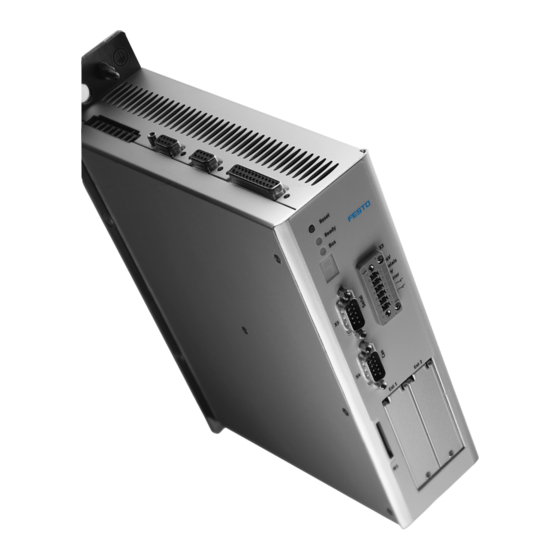
Festo CMMP Series Description
Motor controller for profibus
Hide thumbs
Also See for CMMP Series:
- Description (35 pages) ,
- Manual (210 pages) ,
- Brief overview (86 pages)

Related Manuals for Festo CMMP Series


Summary of Contents for Festo CMMP Series
- Page 1 PROFIBUS for motor controller CMMP… Description PROFIBUS CMMP… Description 557 338 de 0708NH [723 751]...
- Page 3 Edition __________________________________________________ de 0708NH Description ________________________________ P.BE-CMMS-FHPP-PB-SW-EN Order no ____________________________________________________ 557 338 (Festo AG & Co KG., D-73726 Esslingen, 2008) Internet: http://www.festo.com E-mail: service_international@festo.com The copying, distribution and utilization of this document as well as the communication of its contents to others without expressed authorization is prohibited. Offenders will be held liable for compensation of damages.
- Page 4 File name: File saved at: Consec. no. Description Index of revisions Date of amendment Produced 0708NH 21.04.2008 Trade names PROFIBUS, PROFIBUS-DP® are registered trade marks of PROFIBUS International (P.I.) SIMATIC® is registered trade mark of Siemens AG Festo P.BE-CMMS-FHPP-PB-SW-EN en 0708NH...
-
Page 5: Table Of Contents
Table of contents General information ....................6 Documentation ...................... 6 Festo Profile for Handling and Positioning (FHPP) ..........6 Data exchange in the PROFIBUS ................7 Safety instructions for electric drives and controllers ..........8 Icons and signs ...................... 8 General instructions .................... -
Page 6: General Information
The documentation contains safety instructions which must be observed. Festo Profile for Handling and Positioning (FHPP) Festo has developed an optimised data profile, the "Festo Handling and Positioning Profile (FHPP)", tailored to the target applications for handling and positioning tasks. -
Page 7: Data Exchange In The Profibus
PROFIBUS-DP can be found for fast data exchange in manufacturing technology and building automation (DP = decentral periphery). The incorporation into the ISO/OSI layer model is also described in this standard. Further information, contact addresses etc. can be found under www.PROFIBUS.com Festo P.BE-CMMS-FHPP-PB-SW-EN en 0708NH... -
Page 8: Safety Instructions For Electric Drives And Controllers
The safety instructions contain reference to dangerous voltages which may occur. General instructions Festo AG & Co. KG is not liable for damage caused by failure to observe the warning instructions in these operating instructions. Note Before commissioning you must read the “Safety instructions for electric drives and controllers”... - Page 9 Request that the operating instructions are sent immediately to the responsible person, in order that the motor controller can be operated correctly and safely. These safety instructions must also be provided if the motor controller is sold, lent and/or passed on to third parties. Festo P.BE-CMMS-FHPP-PB-SW-EN en 0708NH...
-
Page 10: Dangers Due To Incorrect Use
DANGER! Surfaces of the device housing may be hot. Danger of injury. Danger of burning. Warning DANGER! Dangerous movements. Danger of death, serious bodily injury or damage to property due to unintentional movement of the motors. Festo P.BE-CMMS-FHPP-PB-SW-EN en 0708NH... -
Page 11: Safety Instructions
Warning The environmental conditions specified in the product documentation must be observed. Safety-critical applications are not permitted if they are not explicitly approved of by the manufacturer. Festo P.BE-CMMS-FHPP-PB-SW-EN en 0708NH... -
Page 12: Safety Instructions For Assembly And Maintenance
The system manufacturer or the user is responsible for ensuring that these regulations are observed. Warning The operation, maintenance and/or commissioning of the motor controller may only be carried out by trained qualified personnel and with electrical appliances suited for this work. Festo P.BE-CMMS-FHPP-PB-SW-EN en 0708NH... - Page 13 Make sure also that the external voltage supply of the controller (24 V) is switched off. The intermediate circuit or the mains voltage must always be switched off before the 24 V controller supply is switched off. Festo P.BE-CMMS-FHPP-PB-SW-EN en 0708NH...
-
Page 14: Protection Aganst Touching Electric Components
For operation the relevant DIN, VDE, EN und IEC regulations, as well as all national and local safety and accident prevention regulations must always be observed. The system manufacturer or the user is responsible for ensuring that these regulations are observed. Festo P.BE-CMMS-FHPP-PB-SW-EN en 0708NH... - Page 15 During installation note the amount of intermediate circuit voltage, especially with regard to insulation and protective measures. Make sure that the earthing, the cross section size of the conductor and the corresponding short-circuit protection are correct. Festo P.BE-CMMS-FHPP-PB-SW-EN en 0708NH...
-
Page 16: Protection By Low Voltage (Pelv) Against Electric Shock
Faults in the measured value and signal generators Defective or non-EMC valid components Faults in the software in the higher-order control system These faults can occur immediately after the device is switched on or after a certain period of operation. Festo P.BE-CMMS-FHPP-PB-SW-EN en 0708NH... -
Page 17: Protection Aganst Touching Hot Components
After switching devices off, leave them for 10 minutes to cool down before touching them. If you touch hot parts of the device such as the housing which contains the heat sink and resistors, you may burn yourself. Festo P.BE-CMMS-FHPP-PB-SW-EN en 0708NH... -
Page 18: Protection When Handling And Assembling
Use lifting devices and tools in a correct manner. If necessary, use suitable protective equipment (e.g. protective glasses, safety shoes, safety gloves). Do not stand under hanging loads. Wipe up spilt liquids on the floor to avoid slipping. Festo P.BE-CMMS-FHPP-PB-SW-EN en 0708NH... -
Page 19: Assembly And Installation
9-pin sub-D socket two DIP switches for actuating the terminating resistors. 1 Two DIP switches 2 9-pin sub-D socket 3 LED for the bus readiness message Fig. 3.1: Connecting and display elements on the PROFIBUS-DP interface Festo P.BE-CMMS-FHPP-PB-SW-EN en 0708NH... -
Page 20: Assembly
Philips screw. Make sure that the front plate fits flush with the front in order that it has conductive contact with the housing. Front cover Fig. 3.2: Unscrew front cover Festo P.BE-CMMS-FHPP-PB-SW-EN en 0708NH... -
Page 21: Installation
If the cabling is not correct, faults may occur on the PROFIBUS which cause the motor controller to switch off with a fault for safety reasons. Festo P.BE-CMMS-FHPP-PB-SW-EN en 0708NH... -
Page 22: Pin Assignment Of Profibus Interface
Reference potential GND 5V Use for external bus termination or for suppling transmitter/receiver of an external LWL module. Signal is optional, serves for direction control when used with an external LWL module. Tab. 3.1: Connector pin assignment: PROFIBUS-DP interface Festo P.BE-CMMS-FHPP-PB-SW-EN en 0708NH... -
Page 23: Termination And Bus Terminating Resistors
Fig. 3.5: Bus termination If the set baud rate is greater than 1.5 MBaud, plugs with integrated series inductance (110 nH) must be used due to the capacitive load of the slave and the cable reflexion thereby created. Festo P.BE-CMMS-FHPP-PB-SW-EN en 0708NH... -
Page 24: Configuration Of The Profibus Module
2. Parametrizing and commissioning with the FCT. Especially also the setting physical units. 3. Configuration of the PROFIBUS master. For correct functioning it is necesary to define the physical units of the processing data transmitted via the field bus. These can be set via the FCT. Festo P.BE-CMMS-FHPP-PB-SW-EN en 0708NH... -
Page 25: Setting The Slave Address
All parameters are only valid when the PROFIBUS communication is deactivated and then re-activated. Please note that the PROFIBUS communication can only be acti- vated when the parameter records have been saved and a Reset has been carried out. Festo P.BE-CMMS-FHPP-PB-SW-EN en 0708NH... -
Page 26: Profibus Configuration
FCT without connection to the PROFIBUS be carried out first. Note on commissioning with the Festo Configuration Tool can be found in the help to the device-specific FCT PlugIn. Important processing data for position, velocity and acceleration are transferred in physical units. -
Page 27: Configuration With Simatic Manager
(HW Config) –SIMATIC…). The motor controller CMMP can be found under "PROFIBUS-DP\Additional Field Devices \Drives\Festo"). 1. Pull the station type "Festo CMMP" by drag and drop onto the PROFIBUS-DP master system. Festo P.BE-CMMS-FHPP-PB-SW-EN en 0708NH... - Page 28 2 x 8 bytes of I/O data, As FHPP standard, additional 8 bytes I/O data for + FPC consistent transmission parametrizing Tab. 4.4: Configuration The I/O addresses can be defined with a double click on the location. Festo P.BE-CMMS-FHPP-PB-SW-EN en 0708NH...
- Page 29 4. When the configuration is concluded, transfer the data to the master. Control and parametrizing methods and the functioning of the parametrizing can be found in manual CMMP-AS-PB-S7-EN. System functions used An example of a project and the documentation CMMP-AS-PB-S7 can be found on the CD. Festo P.BE-CMMS-FHPP-PB-SW-EN en 0708NH...
-
Page 30: Diagnosis
Value range of the data and the physical units are not suited together. Contact technical support Tab. 5.2: PROFIBUS error codes The following faults concern FHPP, but can also occur if the PROFIBUS module is used: Please refer to the FHPP manual for detailed information. Festo P.BE-CMMS-FHPP-PB-SW-EN en 0708NH... - Page 31 Tab. 5.3: FHPP error codes Fault messages can be quitted with: the parametrizing interface via the field bus (control word), a falling edge at DIN5 (controller enable). Festo P.BE-CMMS-FHPP-PB-SW-EN en 0708NH...
-
Page 32: Technical Specifications
1.5 MBaud 3.0 MBaud 6.0 MBaud 12.0 MBaud Protocol PROFIBUS-DP Interface Potential-isolated, D-SUB 9-pin, integrated switchable bus terminating resistors Special functions Supports diagnostic data, RTS signal, no fail-safe mode, no Sync/Freeze Tab. A.2: PROFIBUS technical specifications module Festo P.BE-CMMS-FHPP-PB-SW-EN en 0708NH...
Need help?
Do you have a question about the CMMP Series and is the answer not in the manual?
Questions and answers