Festo CMMO-ST-C5-1-DIOP Original Instructions Manual
Motor controller
Hide thumbs
Also See for CMMO-ST-C5-1-DIOP:
- Original instructions (4 pages) ,
- Instructions (4 pages) ,
- Manual (22 pages)

Related Manuals for Festo CMMO-ST-C5-1-DIOP


Summary of Contents for Festo CMMO-ST-C5-1-DIOP
- Page 1 Motor controller CMMOST-...-DION/DIOP Description Motor controller with I/O interface CMMO-ST-C5-1-DIOP CMMO-ST-C5-1-DION 8071657 2017-05c [8071659]...
- Page 2 Software markings: <xxx> Buttons in the software [xxx] [xxx] References to menu and sub-menu structures in the software FCT […] [xxx] FCT PlugIn meny for components in the “Workplace” window FCT menu [xxx] FCT-main menu Festo – GDCP-CMMO-ST-EA-SY-EN – 2017-05c –...
-
Page 3: Table Of Contents
............Festo – GDCP-CMMO-ST-EA-SY-EN – 2017-05c – English... - Page 4 ......... Festo – GDCP-CMMO-ST-EA-SY-EN – 2017-05c – English...
- Page 5 ..........Festo – GDCP-CMMO-ST-EA-SY-EN – 2017-05c – English...
- Page 6 ............Festo – GDCP-CMMO-ST-EA-SY-EN – 2017-05c – English...
-
Page 7: Service
CMMOST-...-DION/DIOP Service Please consult your regional Festo contact if you have any technical problems. Motor controller documentation For all available product documentation è www.festo.com/sp This documentation (GDCP-CMMO-ST-EA-SY-...) describes the functions of the motor controller CMMO-ST-C5-1-DIOP/DION. The full description of the motor controller includes the following... - Page 8 Additional information about the product: – Brief documentation (Quick Start Guide) for initial start-up and diagnostics of posi tioning systems in Festo's Optimised Motion Series (OMS) with the web server of the CMMO-ST (in scope of delivery) – Overview of accessories (catalogue) è www.festo.com/catalogue –...
-
Page 9: Safety And Requirements For Product Use
• Protect the motor controller to prevent accidental touching. • Inform operating and maintenance staff about any potential hazards. • Before touching the product, e.g. for mounting or installation: Allow the motor con troller to cool down to room temperature. Festo – GDCP-CMMO-ST-EA-SY-EN – 2017-05c – English... -
Page 10: Use For Intended Purpose
Use for intended purpose The motor controller CMMO-ST is intended for controlling the following actuators: – Positioning systems in the Optimised Motion Series (OMS) with axis/motor units from Festo, e.g. EPCO electric cylinder – Configurable actuators with the following components –... -
Page 11: Requirements For Product Use
– electrical control technology – the applicable regulations for operating safety-engineered systems – the applicable regulations for accident prevention and industrial safety – the documentation for the product Festo – GDCP-CMMO-ST-EA-SY-EN – 2017-05c – English... -
Page 12: Product Conformity And Certifications
The technical data stated therein take priority. The technical data in this documentation may show values deviating from this. Additional information: – Certificates and the declaration of conformity for this product è www.festo.com/sp – Other standards and test values è Appendix A.1 1.2.6... -
Page 13: Product Description
(Festo Configuration Tool) integrated in Functional earth with earth plate (protective ground è Special documentation CMMO-ST Higher-order controller (SPS/IPC) for control CMMO-ST_SPUL) via I/O interface e.g. CECC Fig. 2.1 System structure (example) Festo – GDCP-CMMO-ST-EA-SY-EN – 2017-05c – English... -
Page 14: Product Overview
00-0E-F0-40-C5-49 address 24 V DC. max. 5.7 A Connection data 00000001 Data matrix code Coded serial number 234567 (corresponds to the number below the code) Tab. 2.1 Product labelling of motor controller (example) Festo – GDCP-CMMO-ST-EA-SY-EN – 2017-05c – English... - Page 15 Product description The product key of the product can be entered as a search term in the Festo Support Portal to determ ine the revision of the device (è www.festo.com/sp). The type code on the product labelling indicates the equipment features of the various versions of the motor controller.
-
Page 16: Scope Of Delivery And Accessories
NEBC-S1G25-K-...-.0-N-S1G25 – Motor and encoder cables NEBM-... in accordance with the actuator configuration in various plug connector versions and lengths – I/O simulation box CDSM-S3-P/N with manual control unit, interconnecting cable, user manual Festo – GDCP-CMMO-ST-EA-SY-EN – 2017-05c – English... -
Page 17: Product Features
– Diagnostic memory via web server and FCT 1) Current regulation in accordance with actual load leads to lower levels of heat generation. 2) No new homing is required, e.g. after emergency stop. Tab. 2.6 Product features Festo – GDCP-CMMO-ST-EA-SY-EN – 2017-05c – English... -
Page 18: Supported Motor Configurations
The actuator can move freely once the controller has been inhibited. With holding brake After inhibiting the controller, the actuator is maintained in position by the holding brake. Tab. 2.7 Motor configuration: holding brake Festo – GDCP-CMMO-ST-EA-SY-EN – 2017-05c – English... - Page 19 – Force Comparator – Force mode 1) For specific applications, the “open-loop operation” function can be set with FCT. This function corresponds to that of a motor without encoder. Tab. 2.8 Motor configuration: encoder Festo – GDCP-CMMO-ST-EA-SY-EN – 2017-05c – English...
-
Page 20: Software For Configuration And Commissioning
2.3.1 FCT (Festo Configuration Tool) The Festo Configuration Tool (FCT) is the Windows-based software platform for parameterisation, com missioning and diagnosis of actuators with configurable motor-axis combinations and positioning systems (OMS). To prepare for commissioning, parameterisation on the PC can take place without a connection to the controller (“offline”). - Page 21 – Recording of measuring data in real time, e.g. to evaluate the control characteristics – Monitoring of the output stage temperature – Readout/deletion of the diagnostic memory – Firmware download in service cases – Restore factory setting Tab. 2.9 Festo Configuration Tool (FCT), Plugin CMMO-ST Festo – GDCP-CMMO-ST-EA-SY-EN – 2017-05c – English...
-
Page 22: Web Servers
– Downloading a parameter file, e.g. to restored settings – Password protection – Simplified commissioning of positioning systems (OMS): Valve – Download of tested parameter files from the Festo Internet Server (“Parameter Cloud”) – Carrying out homing – Jogging and teaching –... -
Page 23: Password Protection
To change or delete, the active password must be known. Changing involves the input of a new pass word. Deletion involves the use of a blank input field Password forgotten? If the password has been forgotten, it can be reset using Festo Service. Festo – GDCP-CMMO-ST-EA-SY-EN – 2017-05c – English... -
Page 24: Parameterisation And Control Interfaces
– The DHPC server on the motor controller is not intended for supplying existing net works with IP addresses. To integrate in a network, the factory setting of the motor controller must be modified before integration in the network è Chapter 5.7.4 Festo – GDCP-CMMO-ST-EA-SY-EN – 2017-05c – English... - Page 25 IP address, or it may be assigned an IP address. 1) Dynamic Host Configuration Protocol Tab. 2.15 Integration in a network via Ethernet Festo – GDCP-CMMO-ST-EA-SY-EN – 2017-05c – English...
-
Page 26: Control Profiles Of The I/O Interface (Valve, Binary)
A web server start-up requires the valve profile to be set for the I/O interface. A change of profile via web server involves the downloading of a corresponding parameter file to the motor controller. All OMS parameter files from Festo contain “Valve Profile” parameterisation. -
Page 27: Device Control (Master Control)
Tab. 2.18 Connections and rights via Ethernet interface An active HTTP connection can always be reconstructed. If the active TCP connection does not have master control, the HTTP connection can assume master control. Festo – GDCP-CMMO-ST-EA-SY-EN – 2017-05c – English... -
Page 28: Time-Out Characteristics
The motor controller does not detect if the connection to a web browser is interrupted. Movements that have been started via the web browser can no longer be stopped by interrupting the Ethernet connections using the browser. Festo – GDCP-CMMO-ST-EA-SY-EN – 2017-05c – English... -
Page 29: Drive Functions
1) This function is only possible via FCT/web server. 2) This function in the valve profile has a reduced functional scope. 3) The function requires close-loop control operation (motor with encoder). Tab. 2.20 Overview of the drive functions Festo – GDCP-CMMO-ST-EA-SY-EN – 2017-05c – English... -
Page 30: Measuring Reference System
Software limit negative (SLN) Software limit positive (SLP) Usable range (usage stroke) Operating range (effective stroke) Direction of movement with the factory setting Dimensional reference system è FCT [...] [Axis] [Measurements] Tab. 2.21 Festo – GDCP-CMMO-ST-EA-SY-EN – 2017-05c – English... - Page 31 Direction of rotation with factory setting, viewing front surface of motor shaft 1) On rotary shafts with “unlimited” configuration, no end position can be parameterised. Dimensional reference system è FCT [...] [Axis] [Measurements] Tab. 2.22 Festo – GDCP-CMMO-ST-EA-SY-EN – 2017-05c – English...
- Page 32 “software limit” error message is displayed. If the target is in the permitted range, it is possible to move out of the software limit position without an error. Festo – GDCP-CMMO-ST-EA-SY-EN – 2017-05c – English...
-
Page 33: Homing
– Inactive Reference travel (homing) is not carried out auto matically (factory setting): Tab. 2.25 Automatic start è FCT [...] [Axis] [Homing] Settings Festo – GDCP-CMMO-ST-EA-SY-EN – 2017-05c – English... - Page 34 Device control Status display FCT online tab: Homing Web servers Web pages “Diagnosis”, “Parameters” I/O interface Referenced: DOUT9 Reference travel enabled/reference travel valid: configurable for DOUT6 … 7 Tab. 2.27 Status display for homing Festo – GDCP-CMMO-ST-EA-SY-EN – 2017-05c – English...
- Page 35 • Select low search/crawl speed to enable the target points to be identified as accurately as pos sible. • Set deceleration high enough to prevent the target points from being overrun during the search run. Festo – GDCP-CMMO-ST-EA-SY-EN – 2017-05c – English...
- Page 36 The current position is taken as the homing point. A movement only takes place if the “Position to axis zero point” option is enabled. 1) Homing option “Position to axis zero point” è Tab. 2.26 Tab. 2.30 Homing method – current position Festo – GDCP-CMMO-ST-EA-SY-EN – 2017-05c – English...
- Page 37 The position of the next index is taken as the homing point. 2. Optional: travel to the axis zero point. Direction: positive (method 22 ; 34) Direction: negative (method 21 ; 33) Index Index Tab. 2.31 Homing method – homing to index Festo – GDCP-CMMO-ST-EA-SY-EN – 2017-05c – English...
- Page 38 3. Travel to the axis zero point Direction: positive Direction: negative 1) Homing option “Position to axis zero point” must be enabled. è Tab. 2.26 Tab. 2.32 Homing method – homing to stop Festo – GDCP-CMMO-ST-EA-SY-EN – 2017-05c – English...
- Page 39 1) If the reference switch is enabled when a homing run starts, step 2 is executed immediately 2) FCT [...] [Axis] [Homing] Settings: Timeout 3) Homing option “Position to axis zero point” è Tab. 2.26 Tab. 2.33 Homing method – reference switch without index Festo – GDCP-CMMO-ST-EA-SY-EN – 2017-05c – English...
- Page 40 On positioning systems (OMS) with a reference switch, during assembly the angle posi tion of the encoder is determined. Then the mechanism is installed at Festo in such a way that the index impulse is far enough away from the reference switch.
-
Page 41: Jogging
– As the flank of the jog signal declines, the actuator with the parameterised delay is brought to a standstill. If both signals (Jog+/Jog- ) are present at the same time, Jog- is preferred. Festo – GDCP-CMMO-ST-EA-SY-EN – 2017-05c – English... - Page 42 With FCT the actuator can also be positioned in single steps. Homing is required for posi tioning in single steps. Increment and speed can be parameterised in FCT. For more information: è FCT PlugIn help, position manually Festo – GDCP-CMMO-ST-EA-SY-EN – 2017-05c – English...
-
Page 43: Teaching
The position is saved permanently using the “Auto matic saving” option. If this option is not set, permanent saving via FCT or web server is possible. Other information è Chapter 5.6.7 Festo – GDCP-CMMO-ST-EA-SY-EN – 2017-05c – English... -
Page 44: Stopping
Through removal of controller enable, the current actuator function can be terminated. After braking to a stop with the parameterised Quick-Stop retardation function, the closed-loop controller is blocked. The actuator is not controlled after this. Festo – GDCP-CMMO-ST-EA-SY-EN – 2017-05c – English... -
Page 45: Actuating The Holding Brake
After that, the controller is disabled. The switch-on delay must be set in such a way that the holding brake finishes up completely closed. Tab. 2.39 Parameterisation of the holding brake è FCT [...] [Motor], Brake control Festo – GDCP-CMMO-ST-EA-SY-EN – 2017-05c – English... - Page 46 When the closed-loop controller is blocked, the holding brake can be opened – Via I/O interface [X1.9] DIN BRAKE CONTROL = 1 – With FCT (“Project output” window, device control: disable “Brake”) After opening the holding brake, the actuator can be moved manually. Festo – GDCP-CMMO-ST-EA-SY-EN – 2017-05c – English...
-
Page 47: Positioning Mode
Final speed of the order (standard = 0) 1) Separately adjustable in FCT if the asymmetric ramp generator has been enabled. Otherwise identical to acceleration. 2) Parameterisation for record linking (binary profile) Tab. 2.41 Parameter for influencing the track characteristics Festo – GDCP-CMMO-ST-EA-SY-EN – 2017-05c – English... - Page 48 Tab. 2.42 Target recognition in positioning mode speed Acceleration Deceleration Target position Start Motion complete Fig. 2.5 Positioning order – example: start speed and setpoint final speed 0 mm/s, without reverse limiting Festo – GDCP-CMMO-ST-EA-SY-EN – 2017-05c – English...
-
Page 49: Velocity Mode
Lower values cause gentler braking action. The value “0” means that no reverse limiting is enabled. 1) Separately adjustable in FCT if the asymmetric ramp generator has been enabled. Otherwise identical to acceleration. Tab. 2.44 Parameter for influencing the track characteristics Festo – GDCP-CMMO-ST-EA-SY-EN – 2017-05c – English... - Page 50 Tab. 2.45 Target recognition in velocity mode Festo – GDCP-CMMO-ST-EA-SY-EN – 2017-05c – English...
- Page 51 (internal) Fig. 2.6 Stroke limitation reached before target speed - example Stroke limit Target speed Actual speed Motion complete Stroke limitation reached (internal) Fig. 2.7 Stroke limitation reached after target speed - example Festo – GDCP-CMMO-ST-EA-SY-EN – 2017-05c – English...
-
Page 52: Force Mode
The speed remains limited to the maximum value specified in the order. Stroke limitation remains active. Tab. 2.48 Target recognition in force mode Festo – GDCP-CMMO-ST-EA-SY-EN – 2017-05c – English... -
Page 53: Operational Principle For Record Selection
TCP/IP applications is required (è Appendix B.1, Control via Ethernet [CVE]) Record selection with FCT Single records can be started from the record table for test purposes. Also, records can be compiled in any order and executed as a sequence (test cycle). Festo – GDCP-CMMO-ST-EA-SY-EN – 2017-05c – English... - Page 54 Maximum permitted distance for execution of the order (Stroke limit) Max. Following Error Control deviation in positioning or velocity mode at which the (Max. Following Error) message “following error” is issued Tab. 2.50 Record parameter Festo – GDCP-CMMO-ST-EA-SY-EN – 2017-05c – English...
-
Page 55: Record Switching
Example: “ignore” start condition The start signal (here for record B) is ignored. The current order (here record A) is completed. Target position record A Start record Motion Complete Fig. 2.8 “Ignore” start condition Festo – GDCP-CMMO-ST-EA-SY-EN – 2017-05c – English... - Page 56 The current task (here record A) is interrupted immediately and the newly addressed task (here record B) is executed directly. Target position, record B Target position record A Start record Motion Complete Fig. 2.10 Start condition “Interrupt” Festo – GDCP-CMMO-ST-EA-SY-EN – 2017-05c – English...
-
Page 57: Record Linking
Force comparator active ... the force is within the force/torque window Time comparator active ... the length of time for which order processing is in the time window Tab. 2.53 Step enabling conditions Festo – GDCP-CMMO-ST-EA-SY-EN – 2017-05c – English... - Page 58 The force continues to be limited to the maximum value defined in the order. A subsequent order can start without the actuator being at a standstill. Tab. 2.54 Target recognition (message “Motion Complete”) in positioning mode Festo – GDCP-CMMO-ST-EA-SY-EN – 2017-05c – English...
- Page 59 Setpoint speed record B Setpoint speed record A Final velocity record A Position B Position A Start record sequence Motion Complete (MC visible) Fig. 2.11 Subsequent record with final velocity v ≠ 0 Festo – GDCP-CMMO-ST-EA-SY-EN – 2017-05c – English...
-
Page 60: Monitoring Of The Actuator Behaviour
Motion Complete message (order ended) is triggered. Motion Complete t1: Damping time, Motion Complete Actual speed Time window, Motion Complete Setpoint speed Fig. 2.12 Motion Complete – example of velocity mode Festo – GDCP-CMMO-ST-EA-SY-EN – 2017-05c – English... - Page 61 (2F ) (è FCT error management). If the following error was configured as a warning, the message is deleted automatically once the actual value once again lies inside the following error win dow. Festo – GDCP-CMMO-ST-EA-SY-EN – 2017-05c – English...
- Page 62 The standstill monitoring cannot be switched on or off. It is disabled when the standstill window is set to the value “0”. The error management functionality of FCT makes it possible to parameterise the response to this message (37F ) (è FCT error management). Festo – GDCP-CMMO-ST-EA-SY-EN – 2017-05c – English...
-
Page 63: Comparators
The message is enabled if – Time the actual value for the parameterised time lies within the window. 1) Only present in closed-loop operation. Tab. 2.57 Comparators Festo – GDCP-CMMO-ST-EA-SY-EN – 2017-05c – English... -
Page 64: Protective Functions
If the temperature drops be low or rises above a limit value, an error mes sage is triggered 1) The response to the malfunction can be parameterised è FCT [...] [Controller] [Error Management]. Tab. 2.58 Protective functions Festo – GDCP-CMMO-ST-EA-SY-EN – 2017-05c – English... -
Page 65: Mounting
• Never remove or insert interconnecting cables when the motor controller is powered. • Observe the handling specifications for electrostatically sensitive devices. Installation dimensions Fig. 3.1 Installation dimensions Dimension [mm] 118.7 103.1 108.8 Tab. 3.1 Installation dimensions Festo – GDCP-CMMO-ST-EA-SY-EN – 2017-05c – English... -
Page 66: Mounting On An H-Rail
4. Press motor controller against the H-rail until the bracket engages. 5. When installing several controllers, maintain the specified minimum distance. max. 5 mm Fig. 3.2 H-rail installation Dimension [mm] 61.35 Tab. 3.2 Minimum distance of motor controller during H-rail installation Festo – GDCP-CMMO-ST-EA-SY-EN – 2017-05c – English... -
Page 67: Mounting On A Mounting Plate
• Bolt device into place using 4 x M4 screws. • If necessary, use washers / spring washers. Remove the H-rail clip Mounting surface Mounting surface Recesses (2x) Recesses (3x) Bores (2x) Fig. 3.3 Mounting on an even surface Festo – GDCP-CMMO-ST-EA-SY-EN – 2017-05c – English... -
Page 68: Electrical Installation
– braided cable, alternatively: cable with min. cross section of 2.5 … 4 mm² Depending on the installation situation, a different cable may be required. Functional earth connection Size Counterplug Flat pin 6.3 x 0.8 Flat connector sleeve Tab. 4.1 Functional earth connection Festo – GDCP-CMMO-ST-EA-SY-EN – 2017-05c – English... -
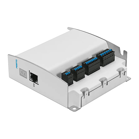
Page 69: Connections And Cables
• Seal unassigned plug connectors with protective caps. [X9] Power supply [X1] I/O (SPC/IPC) [X18] Ethernet [X1A] Reference switch [X3] STO [X2] Encoder [X6] Motor FE function earth (3x) ’ Fig. 4.1 Ports Festo – GDCP-CMMO-ST-EA-SY-EN – 2017-05c – English... - Page 70 [X18] Ethernet Screened 1) This cable is available as an accessory è www.festo.com/catalogue. 2) The cable must be packaged by the customer. 3) Standard network cable. Applicable for the fieldbus length are the specifications for Ethernet networks according to ANSI/TIA/EIA-568-B.1.
-
Page 71: X1] I/O Interface
Damage to the device in the event of an overload / short circuit The auxiliary supply to Pin 24 (+24 V Out) is not overload-proof (I = 100 mA) max. • Only use auxiliary power supply for switching the digital inputs. Festo – GDCP-CMMO-ST-EA-SY-EN – 2017-05c – English... - Page 72 Fig. 4.2 Connection of interface variant PNP (CMMO-...DIOP) X1: NPN Switches DIN1 DIN2 DIN10 DIN11 DOUT1 DOUT2 DOUT10 DOUT11 24 V OUT Fig. 4.3 Connection of interface variant NPN (CMMO-...DION) Festo – GDCP-CMMO-ST-EA-SY-EN – 2017-05c – English...
-
Page 73: X1A] Reference Switch
Installation 4.3.2 [X1A] Reference switch The types listed in the Festo catalogue for the respective actuator are suitable for use as reference switches (è www.festo.com/catalogue). Connection Function +24 V Voltage output for supplying the LOGIC OUT reference switch. No overload protection. -
Page 74: X2] Encoder
An incremental encoder with AB signals in accordance with RS422 can be connected at connection [X2]. The ready-to-use cables from Festo (è www.festo.com/catalogue) offer sufficiently large cable cross sections as well as screening of the motor/encoder cable with earth contact on both sides for connec... -
Page 75: X3] Sto
Damage to the device in the event of an overload Pin 1 (+24 V Out) is not overload-proof (max. 100 mA). The logic supply can be option ally used to supply external, active sensors. Festo – GDCP-CMMO-ST-EA-SY-EN – 2017-05c – English... -
Page 76: X6] Motor
Installation 4.3.5 [X6] Motor The ready-to-use cables from Festo (è www.festo.com/catalogue) offer sufficiently large cable cross sections as well as screening of the motor/encoder cable with earth contact on both sides for connec ted components. Connection Function String A Connection of the two motor strings... -
Page 77: X9] Power Supply
– I/O interface +24 V DC supply of the power output stage and the motor (load voltage) Tab. 4.9 Connection [X9] without plug connector and with plug connector fitted (assortment of plugs NEKM-C-10) Festo – GDCP-CMMO-ST-EA-SY-EN – 2017-05c – English... -
Page 78: X18] Ethernet Interface
The motor controller supports the function “crossover detection” (Auto-MDI/MDI-X). To connect the motor controller to the network or to a PC, this means you can choose between patch cables or cros sover cables. The circuitry for network connections [X18] is adapted automatically. Festo – GDCP-CMMO-ST-EA-SY-EN – 2017-05c – English... -
Page 79: Commissioning
• Initial start-up with web server (è Chapter 5.3 ) -or- • Perform first start-up with FCT (è Chapter 5.4 ) Each time after switching on the (logic) power supply • Executing a reference run Festo – GDCP-CMMO-ST-EA-SY-EN – 2017-05c – English... -
Page 80: Establish An Ethernet Connection
1. Install and start FCT (è Chapter 5.4.1) Test with FCT 2. Configure the FCT interface. 3. With FCT menu [Component] [Online] [Login] establish an online connection. Tab. 5.1 Connection of motor controller as active DHCP server (factory setting). Festo – GDCP-CMMO-ST-EA-SY-EN – 2017-05c – English... - Page 81 – Obtain DNS server address automatically. For setting up the network configuration Windows administrator rights are required. • Establish the current address of the motor controller with FCT (è FCT menu [Component] [FCT Interface] <Scan...>). Festo – GDCP-CMMO-ST-EA-SY-EN – 2017-05c – English...
-
Page 82: Commissioning Via Web Server
During start-up with the web server, parameterisation is performed by a parameter file. Parameter files tested by Festo (*fpf ) with standard settings for the positioning systems (OMS) can be found on the Internet and on the CD-ROM provided. If there is no Internet connection the download can be made directly from the CD-ROM. -
Page 83: Web Server Call
1) By scrolling, the individual components of the website can be moved into the visible section of the window 2) Active signals are marked with a blue dot. Inactive signals are marked with a grey dot. 3) The section is only available for positioning systems (OMS) Tab. 5.2 Website“Diagnosis” and“Parameters” Festo – GDCP-CMMO-ST-EA-SY-EN – 2017-05c – English... -
Page 84: Access Via Web Browser To The Motor Controller
Using check box“Control Enable”, the controller and power output stage can be enabled. The motor controller can be controlled via the web browser. To accept via web browser, on the“Parameters” page,“Control” section, • Enable“Device Control”. • Enable“Control Enable”. Festo – GDCP-CMMO-ST-EA-SY-EN – 2017-05c – English... -
Page 85: Configuring And Parameterising The Actuator
3. Search for file (Parameter upload/download: <Search>) 4. Save file (Parameter upload/download: <Save>) Alternatively, you can search for the file in the Festo Support Portal and save it to the PC before the download è www.festo.com/sp, CMMO-ST Downloading the parameter file (*.fpf ) In a download, the selected parameter file is written to the permanent memory of the motor controller: 1. -
Page 86: Executing A Homing Run
• Move actuator in both directions with <Jog neg.> or <Jog pos.>. • Check displayed positions of the axis. • Move to the limits of the positioning range and check the software end positions. Festo – GDCP-CMMO-ST-EA-SY-EN – 2017-05c – English... -
Page 87: Creating And Testing Sets Of Commands
Default values for sets of commands (speed, acceleration, limitations etc.) are predefined for Festo components and can if required be altered in the FCT è FCT [...] [Controller] [Default Values]. The default values are adopted automatically for each record when an absolute position is being taught. -
Page 88: Completing Commissioning
To create a compatible parameter file for firmware . V1.1.2.4 all current parameters are also saved in the parameter file of the controller with <Apply>. For further information about password protection è Chapter 2.3.3 Festo – GDCP-CMMO-ST-EA-SY-EN – 2017-05c – English... -
Page 89: Cmmost
Prerequisites for commissioning: The following information must be presented for the drive configuration and for application purposes: – Type designation or OMS-ID for Festo drive components (optional: type code, parts number) – Properties of the motor and axis – Type of reference switch and referencing method –... -
Page 90: Configuring And Parameterising The Actuator
• Insert component in the project (component selection [Festo] [CMMO-ST] • Create new actuator configuration (Configuration Assistant) If the actuator comprises Festo components, component-specific parameters and limit values are pre defined when creating the actuator configuration. If the actuator contains components from other man... - Page 91 The motor controller can be controlled via FCT. 1. Create an online connection with the FCT menu [Component] [Online] [Login]. 2. In the FCT online tab, enable “FCT” at Device Control. • Enable “FCT” . • “Enable” enable. Festo – GDCP-CMMO-ST-EA-SY-EN – 2017-05c – English...
-
Page 92: Executing A Homing Run
• Move actuator in both directions with <Single Step.> or <Jog>. • Check displayed positions of the axis. • Move to the limits of the positioning range and check the software end positions. Festo – GDCP-CMMO-ST-EA-SY-EN – 2017-05c – English... -
Page 93: Creating And Testing Command Records
Default values for command records (speed, acceleration, limitations etc.) are predefined for Festo components and can if required be altered in the FCT è FCT [...] [Controller] [Default Values]. The default values are adopted automatically for each record when a record type is selected. -
Page 94: Completing Commissioning
• After a restore: reboot the motor controller using the FCT menu [Component] [Online] “Restart Con troller” (or Power on/off ) Further information, e.g. about how to restore the parameterisation of the motor control ler è Can be found in the FCT PlugIn Help Festo – GDCP-CMMO-ST-EA-SY-EN – 2017-05c – English... - Page 95 After that, the password is permanently stored in the motor controller. To create a compatible parameter file for firmware . V1.1.2.4: • Save parameter file in the controller via FCT <Store>. For further information about password protection è Chapter 2.3.3 Festo – GDCP-CMMO-ST-EA-SY-EN – 2017-05c – English...
-
Page 96: Control Via I/O Control Unit Profile (Valve)
X1.22 Tab. 5.4 Valve profile: digital inputs/outputs The inputs are scanned at intervals (scanning rate tmax = 1 ms). That enables the controller to re spond to an input signal after a delay. Festo – GDCP-CMMO-ST-EA-SY-EN – 2017-05c – English... - Page 97 Controlled braking to a stop with the parameterised deceleration function (Quick Stop). On motor with holding brake: apply the brake. Disabling the controller DIN11 RESET 0è1 Reset an acknowledgeable error Tab. 5.6 Valve profile: function of digital inputs Festo – GDCP-CMMO-ST-EA-SY-EN – 2017-05c – English...
- Page 98 – Input signals [X3] STO1/STO2 = 1 – CONTROL ENABLE = 1 – No error DOUT11 TORQUE LIMIT REACHED The parameterised torque/force limit has been reached. Tab. 5.7 Valve profile: function of digital outputs Festo – GDCP-CMMO-ST-EA-SY-EN – 2017-05c – English...
-
Page 99: Establish Ready Status (Ready)
– On motor with encoder by the time required to search for the commutation angle after the first time the power supply is switched on – On a motor with holding brake in accordance with the parameterised switch-on delay. Festo – GDCP-CMMO-ST-EA-SY-EN – 2017-05c – English... -
Page 100: Acknowledge Error (Reset)
(CONTROL ENABLE 0è1) is required. After that, the motor controller is once again ready for op eration (READY=1). Faults No error RESET DIN11 CONTROL ENABLE DIN10 Ready DOUT10 Time delay t 2 ms Error event Request controller enable Acknowledge error Fig. 5.6 Valve profile: acknowledge error Festo – GDCP-CMMO-ST-EA-SY-EN – 2017-05c – English... -
Page 101: Controller Enable (Control Enable)
Request controller enable Revoke controller enable Controller has been enabled Confirmation that controller is blocked Fig. 5.7 Valve profile: release/inhibit controller Festo – GDCP-CMMO-ST-EA-SY-EN – 2017-05c – English... -
Page 102: Carrying Out Homing (Ref)
The type of switch used (NC/NO) is selected using FCT [...] [Axis] Axis Options. Detailed information about the homing process and about how the homing point is de termined è Chapter 2.5.2 Festo – GDCP-CMMO-ST-EA-SY-EN – 2017-05c – English... -
Page 103: Execute Command Records (Record)
The corresponding output RECORDx REACHED is set. The output remains set while the actuator remains at the target positon (even if the input is reset). Festo – GDCP-CMMO-ST-EA-SY-EN – 2017-05c – English... - Page 104 Record changeover from record 2 to record 1 Stop record 1 Start condition record 1: interrupt Start record 2 Target for record 1 reached Fig. 5.9 Valve profile: e.g. record selection with record switching Festo – GDCP-CMMO-ST-EA-SY-EN – 2017-05c – English...
-
Page 105: Control Via I/O Control Unit Profile (Binary)
– Asymmetric acceleration and deceleration ramp – Changing over the set of commands during movement without an intermediate stop. – Record Linking – Optional: stopping the current actuator function or time delay Unsupported function: – Automatic homing Festo – GDCP-CMMO-ST-EA-SY-EN – 2017-05c – English... -
Page 106: Digital Inputs/Outputs
Tab. 5.10 Logical status In standard cases, logical status “1” is the active status. Inputs/outputs for which the logical status differs, i.e. is “0”, are labelled in Tab. 5.9 with the # symbol. Festo – GDCP-CMMO-ST-EA-SY-EN – 2017-05c – English... - Page 107 Disabling the closed-loop controller. RESET 0è1: In the event of a malfunction: reset an acknowledgeable error - X1.11 or - delete remaining path after PAUSE Tab. 5.11 Binary profile: function of the digital inputs Festo – GDCP-CMMO-ST-EA-SY-EN – 2017-05c – English...
- Page 108 By parameterisation of force limitation in the FCT, a load limit can be displayed on the digital output DOUT X1.11 at which the motor is no longer able to follow the position sequence (following error). An additional following errors message is not then issued. Festo – GDCP-CMMO-ST-EA-SY-EN – 2017-05c – English...
- Page 109 – Overvoltage load (0x1A) – Undervoltage load (0x1B) 1) Information for monitoring the actuator behaviour è Chapter 2.7. 2) Identical to DOUT8 IN ZONE Tab. 5.13 Functions of the freely configurable digital output Festo – GDCP-CMMO-ST-EA-SY-EN – 2017-05c – English...
-
Page 110: Establish Ready Status (Ready)
– On motor with encoder by the time required to search for the commutation angle after the first time the power supply is switched on. – On a motor with holding brake in accordance with the parameterised switch-on delay. Festo – GDCP-CMMO-ST-EA-SY-EN – 2017-05c – English... -
Page 111: Change Between Record Selection And Jog/Teach (Mode)
To avoid malfunctions during mode changeover, the time delay of t . 5 ms must be ob served. Then enable the inputs. Ready DOUT10 MODE DIN8 Mode 1 active Mode 0 active Time delay t 5 ms Fig. 5.11 Binary profile: change between record selection and jog/teach Festo – GDCP-CMMO-ST-EA-SY-EN – 2017-05c – English... -
Page 112: Acknowledge Error (Reset)
(CONTROL ENABLE 0è1) is required. After that, the motor controller is once again ready for op eration (READY=1). ERROR DOUT5 RESET DIN11 CONTROL ENABLE DIN10 Ready DOUT10 Time delay t1 2 ms Error event Request controller enable Acknowledge error Fig. 5.12 Binary profile: acknowledge error Festo – GDCP-CMMO-ST-EA-SY-EN – 2017-05c – English... -
Page 113: Controller Enable (Control Enable)
Request controller enable Revoke controller enable Controller has been enabled Confirmation that controller is blocked Fig. 5.13 Binary profile: release/inhibit controller Festo – GDCP-CMMO-ST-EA-SY-EN – 2017-05c – English... -
Page 114: Carrying Out Homing (Ref)
The type of switch used (NC/NO) is selected using FCT [...] [Axis] Axis Options. Detailed information about the homing process and about how the homing point is de termined è Chapter 2.5.2 Festo – GDCP-CMMO-ST-EA-SY-EN – 2017-05c – English... -
Page 115: Teaching (Teach)
DIN1…3 TEACH DIN6 TEACH ACK DOUT2 Time delay t 2 ms Jog JOG+ started Establish teach readiness Jog JOG+ was stopped Current position was applied Fig. 5.15 Binary profile (mode 1): teaching Festo – GDCP-CMMO-ST-EA-SY-EN – 2017-05c – English... - Page 116 • Only use the TEACH function in combination with automatic storage for commis sioning and not in continuous operation. This would otherwise rapidly use up the permitted number of write cycles. • Disable automatic saving after saving via FCT è FCT [...] [Controller] [I/O Configuration]. Festo – GDCP-CMMO-ST-EA-SY-EN – 2017-05c – English...
-
Page 117: Execute Command Records (Record)
MOTION COMPLETE is set. – Record changeover (start condition for following record: “Interrupt”) The execution of the record is interrupted during selection of the following record and the following record is executed immediately without a stop. Festo – GDCP-CMMO-ST-EA-SY-EN – 2017-05c – English... - Page 118 Time delay t 2 ms Start record Delete remaining path Stop record (PAUSE) Signal for order complete (target reached) Fig. 5.16 Binary profile (Mode 0): e.g. record selection, delete start/stop with remaining path Festo – GDCP-CMMO-ST-EA-SY-EN – 2017-05c – English...
- Page 119 Record x start Target reached (record X+1) Record changeover from record x to record x+1 Start condition record x+1: interrupt Fig. 5.17 Binary operation (mode 0): record switching with start condition = interrupt Festo – GDCP-CMMO-ST-EA-SY-EN – 2017-05c – English...
-
Page 120: Instructions On Operation
FCT makes it possible to update the device firmware. If needed, an older version of the firmware can also be loaded into the motor controller. Festo provides firmware versions on the Internet via the Support Portal (è www.festo.com/sp): • Enter the part number or order code of the product in accordance with the product labelling •... -
Page 121: Integration In A Network
IP configuration of the PC. Permanently set IP configura tions do not become effective until after a reboot (Power OFF, ON). Tab. 5.15 TCP/IPv4 setting for integration in a network Festo – GDCP-CMMO-ST-EA-SY-EN – 2017-05c – English... -
Page 122: Diagnostics
7-segment dis play, it may be the case that not all messages are displayed. Read the diagnostic memory ( ) in order to have all messages displayed (è Chapter 6.2). Festo – GDCP-CMMO-ST-EA-SY-EN – 2017-05c – English... -
Page 123: Display During A Firmware Update
Enable waving function with FCT: • FCT menu [Component] [FCT Interface] open the window “FCT Interface” • With <Search> start the “Festo Field Device Tool” (Netscan) program. All reachable motor controllers are displayed in accordance with the filter setting. • In the Context menu [Identification] of the searched for motor controller, select “On”. -
Page 124: Diagnostic Memory
MM = minutes, SS = seconds, nnn = milliseconds). The time base is the respective switch-on time of the motor controller. Additional info Additional information for Festo Service in respect of complex (Additional Info) malfunctions Tab. 6.2 Displays in the diagnostic memory... -
Page 125: Diagnostic Messages
This especially applies to vertical axes without automatic locking mechanics, clamping units or counterbalancing. • Prevent movement of the passive motor in particular with suspended loads or other external forces, e.g. with a holding brake. Festo – GDCP-CMMO-ST-EA-SY-EN – 2017-05c – English... -
Page 126: Tables
Record deceleration - do not turn off braking ramp on current position records, do not turn off output stage Ending a record - continue to execute the record until Motion Complete, do not turn off output stage Tab. 6.6 Error responses (code letters) Festo – GDCP-CMMO-ST-EA-SY-EN – 2017-05c – English... - Page 127 • This error can also occur if the set motor current is too low to move the shaft and any possible load. Correct the settings for the motor current, if necessary. – Resettable: Error can be reset immediately. Definable error reaction(s): A Festo – GDCP-CMMO-ST-EA-SY-EN – 2017-05c – English...
- Page 128 General error Definable as: F/-/- Diagnostic memory: always An internal error has occurred. • Restart device. If the error occurs frequently, contact Festo Service. – Resettable: Error can be reset immediately. Definable error response(s): B Parameter file invalid Definable as: F/-/- Diagnostic memory: always No valid parameter set stored.
- Page 129 • This error can be reset immediately. Afterwards start a corresponding positioning record or move the drive by using the jogging function. Movements in a positive direction are blocked. – Resettable: Error can be reset immediately. Definable error response(s): A, B, C, E, F Festo – GDCP-CMMO-ST-EA-SY-EN – 2017-05c – English...
- Page 130 • This error can be reset immediately. Afterwards start a corresponding positioning record or move the drive by using the jogging function. Movements in a negative direction are blocked. – Resettable: Error can be reset immediately. Definable error response(s): A, B, C, E, F Festo – GDCP-CMMO-ST-EA-SY-EN – 2017-05c – English...
- Page 131 • Separate device from the entire peripheral equipment and check whether the error is still present after reset. If it is, it means there is an internal defect and the device has to be replaced. – Resettable: Cannot be reset; software reset is necessary. Definable error reaction(s): A Festo – GDCP-CMMO-ST-EA-SY-EN – 2017-05c – English...
- Page 132 • If the error is still present, it means there is an internal defect and the device has to be replaced. – Resettable: Error can be reset immediately. Definable error response(s): B, C, E, F Festo – GDCP-CMMO-ST-EA-SY-EN – 2017-05c – English...
- Page 133 If the error occurs again, please contact Festo Service. – Resettable: Error can be reset immediately. Definable error response(s): F, G Festo – GDCP-CMMO-ST-EA-SY-EN – 2017-05c – English...
- Page 134 • Determine the version of the hardware. You can ascertain the compatible firmware designs and download the appropriate firmware from the Festo website. – If defined as an error: Error can be reset immediately. Definable error reaction(s): A –...
- Page 135 Connection to the FCT has been interrupted. • Check the connection and perform a reset, if necessary. – Resettable: Error can be reset immediately. Definable error response(s): B, C, D, E, F, G Festo – GDCP-CMMO-ST-EA-SY-EN – 2017-05c – English...
- Page 136 Definable as: -/W/- Diagnostic memory: optional An error has occurred during trace recording. • Start a new trace recording. – For parameterisation as a warning: The warning disappears if a new trace has been started. Festo – GDCP-CMMO-ST-EA-SY-EN – 2017-05c – English...
- Page 137 • Clear diagnostic memory. If the error is still present, the device needs to be replaced. – Resettable: Error can be reset immediately. Definable error response(s): F, G Festo – GDCP-CMMO-ST-EA-SY-EN – 2017-05c – English...
- Page 138 • Perform a firmware update. If the error is still present, the memory might be faulty. Then the device must be replaced. – Resettable: Cannot be reset; software reset is necessary. Definable error reaction(s): A Festo – GDCP-CMMO-ST-EA-SY-EN – 2017-05c – English...
- Page 139 – Acknowledgement option: Error can only be acknowledged after the cause is eliminated. Definable error response(s): A, B System information Definable as: -/-/ Diagnostic memory: always A device-specific system event has occurred. • This event is used for extended diagnostics. Festo – GDCP-CMMO-ST-EA-SY-EN – 2017-05c – English...
-
Page 140: Problems With The Ethernet Connection
– Determine the IP configuration and change it 1. Under the FCT menu [Component] [FCT Interface] open the “FCT Interface” window. With <Scan...> start the “Festo Field Device Tool” (Netzscan) program. All reachable motor controllers are dis played in accordance with the filter setting. -
Page 141: Other Problems And Remedies
FCT plug-in to ensure correct settings of the controller parameters. Error in the power supply. Comply with voltage tolerances in accordance with “Technical Data” chapter. Tab. 6.7 Other problems and remedies Festo – GDCP-CMMO-ST-EA-SY-EN – 2017-05c – English... -
Page 142: Maintenance, Care, Repair And Replacement
If used as intended, the product is maintenance-free. Regarding care • Clean the outside of the product with a soft cloth. Repair Repair or maintenance of the product is not permissible. If necessary, replace the complete product. Festo – GDCP-CMMO-ST-EA-SY-EN – 2017-05c – English... -
Page 143: Replacement
1. Ensure that there is no voltage. 2. Secure the system against being switched back on. 3. Loosen all electrical system lines. Disposal Observe the local regulations for environmentally appropriate disposal of electronic mod ules. The product is RoHS-compliant. Festo – GDCP-CMMO-ST-EA-SY-EN – 2017-05c – English... -
Page 144: Technical Appendix
Festo è www.festo.com/sp The specified performance data relate to a max. 10 metre length of length of cable for connection of the motor/encoder. With longer cables: please contact Festo Service. Technical data A.1.1... -
Page 145: Operating And Environmental Conditions
– – 160 … 200 160 … 200 – – Shock load Acceleration [m/s Duration [ms] Shocks per direction ±150 ±300 Continuous shock load Acceleration [m/s Duration [ms] Shocks per direction ±150 1000 Festo – GDCP-CMMO-ST-EA-SY-EN – 2017-05c – English... -
Page 146: Product Conformity And Certifications
Requirements for observing the certified UL conditions if the product is operated in the USA or Canada can be found in the separate UL documentation. Festo – GDCP-CMMO-ST-EA-SY-EN – 2017-05c – English... -
Page 147: Connection Data
[X1] Logic auxiliary power supply +24 V OUT [X1.24] GND [X1.25] Nominal voltage [V DC] 24 – Supply via [X9] – not additionally filter or stabilized Maximum current [mA] Overload protection No overload protection Only use for switching the digital inputs Festo – GDCP-CMMO-ST-EA-SY-EN – 2017-05c – English... -
Page 148: X9] Power Supply
Transmission rate 100 MBit/s Connection of plug connector RJ45, 8-pin Supported protocols TCP/IP, UDP Cable type Industrial Ethernet cable, screened Transmission class Category Cat 5 Connection length Maximum 30 metres to next star point Festo – GDCP-CMMO-ST-EA-SY-EN – 2017-05c – English... -
Page 149: B Control Via Ethernet (Cve)
CMMO-ST. If the drive is in motion when the connection is ended, a Quick Stop func tion is triggered. The TCP port used can be set via FCT. The default port number is 49700. Festo – GDCP-CMMO-ST-EA-SY-EN – 2017-05c – English... -
Page 150: Cve Protocol
SINT32 32 bit signed integer – 2147483648 … 2147483647 0x07 SINT16 16 bit signed integer – 32768 … 32767 0x08 SINT08 8 bit signed integer – 128 … 127 Tab. B.1 Data types Festo – GDCP-CMMO-ST-EA-SY-EN – 2017-05c – English... - Page 151 0x0D 0x0E Object index UINT16 Index of the CVE object to be read. 0x0F 0x10 Object subindex UINT08 Always 0. 0x11 Reserved UINT08 Placeholder (initialise with 0). Tab. B.2 Request “Read CVE object” Festo – GDCP-CMMO-ST-EA-SY-EN – 2017-05c – English...
- Page 152 Data type UINT08 Data type of the CVE object. 0x12 Data byte 1 corresponding Object value to data type of … Data byte K the CVE object Tab. B.3 Response “Read CVE object” Festo – GDCP-CMMO-ST-EA-SY-EN – 2017-05c – English...
- Page 153 Data type of the CVE object to be written. 0x12 Data byte 1 corresponding Object value to data type of … Data byte K the CVE object Tab. B.4 Request “Write CVE object” Festo – GDCP-CMMO-ST-EA-SY-EN – 2017-05c – English...
- Page 154 Data type of the written CVE object. If an attempt has been made to write an object with an invalid data type, the correct data type is returned. Tab. B.5 Response “Write CVE object” Festo – GDCP-CMMO-ST-EA-SY-EN – 2017-05c – English...
- Page 155 The CVE object cannot be written, as the spe Correct the data type. cified data type is incorrect. 0xAD The CVE object cannot be written, as it is pass Cancel the password protection è Chapter 2.3.3 word-protected. Tab. B.6 Confirmation (acknowledge) Festo – GDCP-CMMO-ST-EA-SY-EN – 2017-05c – English...
-
Page 156: Controlling The Drive
6 must be written into this CVE object; before starting a position record the value 1 must be writ ten into this CVE object. The current or last executed drive function can be read via CVE object #121. Festo – GDCP-CMMO-ST-EA-SY-EN – 2017-05c – English... - Page 157 Fig. B.1 Finite state machine of the CMMO-ST Festo – GDCP-CMMO-ST-EA-SY-EN – 2017-05c – English...
- Page 158 Error status. No more positioning movements are executed. Open if the The output stage is either active or inactive depending on the output stage is parameterisation of the error. active Tab. B.7 Description of states Festo – GDCP-CMMO-ST-EA-SY-EN – 2017-05c – English...
- Page 159 Ready to switch on CW.QS (Quick Stop) = 1 CW.EV (Enable Voltage) = 1 CW.SO (Switch on) = 0 Operation enabled è CW.FR (Error Reset) = 0 Switch on disabled CW.EV (Enable Voltage) = 0 Festo – GDCP-CMMO-ST-EA-SY-EN – 2017-05c – English...
- Page 160 CW.SO (Switch on) = 1 Ready to switch on è CW.FR (Error Reset) = 0 Operation enabled CW.EO (Enable Operation) = 1 CW.QS (Quick Stop) = 1 CW.EV (Enable Voltage) = 1 CW.SO (Switch on) = 1 Festo – GDCP-CMMO-ST-EA-SY-EN – 2017-05c – English...
- Page 161 Start Must always be 0. CW.PSOn Power stage on after reset (Output stage on after error reset) CW.FR Error reset CW.STP Stop 9 … 31 Must always be 0. Tab. B.9 Control word Festo – GDCP-CMMO-ST-EA-SY-EN – 2017-05c – English...
- Page 162 Referenced. The drive is referenced. SW.DPB Direction positive blocked. The drive cannot be moved in a positive direction. SW.DNB Direction negative blocked. The drive cannot be moved in a negative direction. Tab. B.10 Status word Festo – GDCP-CMMO-ST-EA-SY-EN – 2017-05c – English...
- Page 163 3. Start the record by writing the control word 0x0000001F. While the positioning record is being ex ecuted the status word exhibits the value 0x00048127. When the record has ended the status word exhibits the value 0x00068427. 4. Reset the start signal by writing the control word 0x0000000F. Festo – GDCP-CMMO-ST-EA-SY-EN – 2017-05c – English...
-
Page 164: Explanation Of Increments
Parameterise the drive completely in FCT and then read objects #218 “Unit of measure ment” and #217 “Power of ten”. Example: #218 = 1, i.e. Metre –6 #217 = –6, i.e. 10 è 1 mm = 1000 SINC Festo – GDCP-CMMO-ST-EA-SY-EN – 2017-05c – English... -
Page 165: List Of Cve Objects
Error with top priority acknowledgement option Error handler Warning with top priority Error handler Power of ten conversion factor Drive functions Unit of measurement conversion factor Drive functions Current target position Drive functions Hardware enable System Festo – GDCP-CMMO-ST-EA-SY-EN – 2017-05c – English... - Page 166 0x03 è Web server The master control may be changed by an interface that does not have this only if it is not blocked via object #4 Block master control. Values: 0 … 255 Festo – GDCP-CMMO-ST-EA-SY-EN – 2017-05c – English...
- Page 167 Current actual force in one-tenth of one percent of the maximum motor current (calculated from the measured current) Unit: ‰ Values: –32768 … 32767 Default: 0 Setpoint position System SINT32 R/-/-/-/- Current Target Pos. Unit: SINC Values: –2147483648 … 2147483647 Default: 0 Festo – GDCP-CMMO-ST-EA-SY-EN – 2017-05c – English...
- Page 168 SINT32 R/-/-/-/- Current nominal acceleration Unit: SINC/s² Values: –2147483648 … 2147483647 Default: 0 Position deviation System SINT32 R/-/-/-/- Current following error = actual position - setpoint position Unit: SINC Values: –2147483648 … 2147483647 Festo – GDCP-CMMO-ST-EA-SY-EN – 2017-05c – English...
- Page 169 Values: 0, 1, 3, 4, 6, –3, –4 Default: 0 #121 Actual operating mode Finite state machine SINT08 R/-/-/-/- Operating mode that is currently being executed. Values: è object #120 Values: –128 … 127 Default: 0 Festo – GDCP-CMMO-ST-EA-SY-EN – 2017-05c – English...
- Page 170 0xFFFF means that no warning is present. Values: 0 … 65535 Default: 65535 #217 Power of ten conversion factor Drive functions SINT08 R/W1/-/-/- è Example in section B.2 Unit: 10 Values: < 0 Default: 0 Festo – GDCP-CMMO-ST-EA-SY-EN – 2017-05c – English...
- Page 171 Bits 1 … 7: reserved Only if all bits are 1 can the finite state machine be switched to the status “Operation enabled” through the control word. Unit: Bit field Values: 0 … 255 Default: 254 Festo – GDCP-CMMO-ST-EA-SY-EN – 2017-05c – English...
- Page 172 Control via Ethernet (CVE) Festo – GDCP-CMMO-ST-EA-SY-EN – 2017-05c – English...
- Page 174 Copyright: Festo AG & Co. KG Ruiter Straße 82 73734 Esslingen Germany Phone: +49 711 347-0 Fax: +49 711 347-2144 Reproduction, distribution or sale of this document or communica E-mail: tion of its contents to others without express authorization is service_international@festo.com...
Need help?
Do you have a question about the CMMO-ST-C5-1-DIOP and is the answer not in the manual?
Questions and answers