
Related Manuals for KMC Controls KMD-7001


Summary of Contents for KMC Controls KMD-7001
- Page 1 Installation & Operation Guide Direct Digital VAV Controllers KMD-7001/7051 - VAV Terminal Units KMD-7002/7052 - Dual Duct VAV Units KMD-7003/7053 - Fan Induction Units 907-019-01C...
- Page 2 Introduction This section provides a brief overview of the KMD-7001, 7002 and 7003 Direct Digital Controllers. These units are intended for use with standard 1/2” round or 3/8” square damper shafts. Note: For installations using a 3/8” round shaft, you will need the HFO-0011 shaft adaptor.
-
Page 3: Installation
Illustration 4. KMD-7003 Controller Connector Detail Installation This section provides important instructions and guidelines for installing the KMD-7001, 7002 and 7003 series controllers. Carefully review this information prior to attempting installation. Preparation Prior to mounting the controller, the rotational limits must be set using stop pins. - Page 4 Installation KMD-7001/7002/7003 Direct Digital Controller Installation & Operation Guide Stop Pin (1 of 2) Stop Selections Illustration 5. Controller Stop Selections To set the rotational limits: Turn the controller over so you have access to the back. Locate the two stop pins installed in the back of the unit. (You will find one pin in a CCW setting and one in a CW setting.)
- Page 5 KMD-7001/7002/7003 Direct Digital Controller Installation & Operation Guide Installation Caution Both stop pins must be installed to prevent actuator damage. If the stop pins are positioned as required, you may leave them in place. If not, remove the appropriate pin(s) and place it in the correct slot.
-
Page 6: Input Connections
Installation KMD-7001/7002/7003 Direct Digital Controller Installation & Operation Guide Input Connections All input and output connections are made using the connectors beneath the access cover. Remove the two screws that secure this cover to remove the cover and complete input and output connections as discussed below. -
Page 7: Airflow Sensor
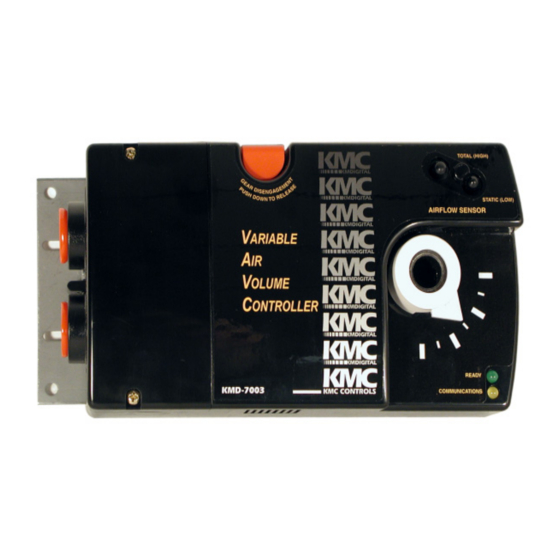
KMD-7001/7002/7003 Direct Digital Controller Installation & Operation Guide Installation Airflow Sensor An Airflow Sensor is incorporated as one of the inputs to the controller. Remove the plugs and connect the tubing from the Pitot assembly to the airflow sensor inputs above the drive hub. (Refer to Illustration 1.) -
Page 8: Power Connection
Installation KMD-7001/7002/7003 Direct Digital Controller Installation & Operation Guide Input Pull-Up/EOL RJ–12 Switches Conn. Illustration 7. Typical Input Pull-up and EOL Switch Placement Proceed as follows: If the access cover is still on the controller, remove the two screws that secure the cover, then remove the cover. -
Page 9: Network Configuration
For electric reheat applications, use a separate 24 VAC transformer to isolate the relay through the Triac. Illustration 8. Typical KMD-7003 Application Note: Typical Application Diagrams may be obtained by contacting KMC Controls Technical Support at 574-831-5250 or e-mail us at techs@kmccontrols.com. Network Configuration Prior to operating the controller, it must be configured using the Hardware Configuration Manager (HCM) application supplied with WinControl. -
Page 10: Operation
Operation Once configured, programmed and powered up, the controller requires very little user intervention. Controls and Indicators The following sections describe the controls and indicators found on the controller. Network ON/OFF The network ON/OFF switch is located near the RJ–12 connector. Use this switch to enable or disable the RS-485 network connection. -
Page 11: Resetting The Controller
KMD-7001/7002/7003 Direct Digital Controller Installation & Operation Guide Operation Resetting the Controller If the controller appears to be operating incorrectly, or is not responding to commands, you may need to reset the controller. Note Resetting the controller will restore the factory default configuration. -
Page 12: Important Notices
The contents and the product(s) described herein are subject to change without notice. KMC Controls, Inc. makes no representations or warranties with respect to this document. In no event shall KMC Controls, Inc. be liable for any damages, direct or incidental, arising out of or related to the use of this document.
Need help?
Do you have a question about the KMD-7001 and is the answer not in the manual?
Questions and answers