Table of Contents
Advertisement
Quick Links
Advertisement
Chapters
Table of Contents

Related Manuals for Graco ProMix II


Summary of Contents for Graco ProMix II
- Page 1 Operation ProMix™ II 310633C For proportional mixing of plural component coatings Important Safety Instructions Read all warnings and instructions in this manual. Save these instructions. See page 3 for model information, including maximum working pressure and approvals.
-
Page 2: Table Of Contents
Power Up Screens ..... . 30 Graco Information ......58 Run Screen . -
Page 3: Promix™ Ii Models
ProMix™ II Models ◆ ProMix™ II Models WARNING WARNING Do not install equipment approved only for a non-haz- Changing the fluid manifold configuration may change ardous location in a hazardous area. Substitution of its pressure rating. Do not exceed the pressure rating components may impair intrinsic safety. -
Page 4: Related Manuals
Related Manuals ◆ Related Manuals Component Manuals in English This manual available in following languages: Manual Description Manual Language Manual Language 310633 ProMix™ II Operation 310633 English 310636 German 310653 ProMix™ II Service - Parts 310634 French 310637 Chinese 310654 Fluid Mix Manifold 310635 Spanish... - Page 5 Related Manuals ◆ 310633C...
-
Page 6: Warnings
Warnings ◆ Warnings The following warnings include general safety information for this equipment. More specific warnings are included in the text where applicable. WARNING FIRE AND EXPLOSION HAZARD Flammable fumes, such as solvent and paint fumes, in work area can ignite or explode. To help prevent fire and explosion: •... - Page 7 Do not alter or modify equipment. • For professional use only. • Use equipment only for its intended purpose. Call your Graco distributor for information. • Route hoses and cables away from traffic areas, sharp edges, moving parts, and hot surfaces. •...
-
Page 8: Overview
Overview Usage The Graco ProMix™ II is an electronic two-component paint proportioner. It can blend most two-component solvent and waterborne epoxy, polyurethane, and acid-catalyzed paints. It is not for use with “quick-setting” paints (those with a potlife of less than 15 minutes). - Page 9 Overview ◆ Component Identification and Definition Component Description Three optional flow meters are available from Graco: Flow Meters • G3000 is a general purpose gear meter typically used in flow ranges of 75-3000 cc/min. (0.02–0.79 gal/min.), pressures up to 4000 psi (28 MPa, 276 bar), and viscosities of 20–3000 centipoise.
-
Page 10: Promix™ Ii General Operating Cycle
ProMix™ II General Operating Cycle ◆ ProMix™ II General Operating Cycle Refer to F Dispense Valve B opens, and fluid flows into the integrator chamber (K) and is aligned pro- portionately with component A. The spray gun operator enters and loads the desired color. -
Page 11: Air Flow Switch Function
ProMix™ II General Operating Cycle ◆ Air Flow Switch Function Key: A Dispense Valve A B Dispense Valve B C Flow Meter A D Component A Supply Line E Air Purge Valve F Shutoff Valve A G Flow Meter B H Component B Supply Line Solvent Purge Valve K Integrator... -
Page 12: Installation
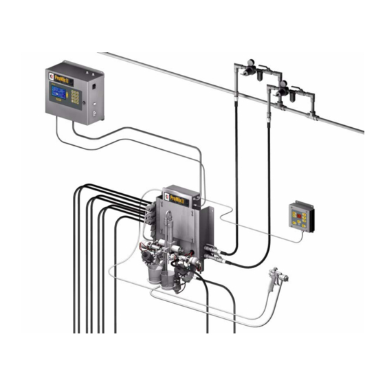
Icons in the text refer to icons on the equipment or keypad. • . 4 and F . 5, page 14, show typical installations. Contact your Graco distributor for actual system designs. • Be sure all accessories are adequately sized and pressure-rated to meet system requirements. - Page 13 Installation ◆ Typical Installation TI4658A 310633C...
-
Page 14: Installation Requirements
Installation ◆ Installation Requirements Installation Requirements NON-HAZARDOUS LOCATION ONLY Operator Power and Station Communication Cable Safety Power Cable 234441 Barrier ProMix™ II Smart ProMix™ II Fiber Optic Fluid Panel EasyKey Communication Pneumatic Cable Interface Interface 234443 Flush 250 VAC Maximum Supply Voltage Flow Flow... -
Page 15: Location Requirements
EasyKey™ Display: Install in the non-hazardous area changeover. If necessary, install pressure regula- at a convenient location for the operator to view and tors or a surge tank on the ProMix™ II fluid inlets to operate. reduce pulsation. Contact your Graco distributor for additional information. 310633C... -
Page 16: Mounting
Installation ◆ Mounting Mounting Dimensions Follow Location Requirements, page 15. EasyKey™ Display Ensure that the wall and mounting hardware are .3 in. strong enough to support the weight of the equip- (7.6 mm) 12 in. ment (see Technical Data, page 56), fluid, hoses, (304.8 mm) and stress caused during operation. -
Page 17: Air Supply Connections
Installation ◆ Air Supply Connections Air Supply Connections Use separate air supply lines for the following two connections (X and L) to avoid contaminating the Required purge air line (X) with fluid if the air purge valve and a check valve failed. •... - Page 18 . 11. . 10 WARNING ™ If using a Graco electrostatic PRO Gun, a shutoff valve must be installed in the gun air line. Contact your Graco distributor for information on air shutoff valves for electrostatic applications. . 11 310633C...
-
Page 19: Fluid Supply Connections
Installation ◆ Fluid Supply Connections Fluid Supply Connections Connect the component B line to the component B flow meter inlet (DD). F . 12. WARNING The component A and B fluid meter inlets (R, DD) have fluid check valves to prevent backflow from fluid supply pressure fluctuations. -
Page 20: Cable Connections
Installation ◆ Cable Connections Cable Connections • All electrical wiring must be done by a qualified electrician and comply with all local codes and regulations. • Enclose all cables routed in the spray booth and high traffic areas in conduit to prevent damage from paint, solvent, and traffic. - Page 21 Installation ◆ Cable Connections Route the opposite Fiber Optic Cable end through Tighten the strain relief connector (D). F the Smart Fluid Panel strain relief connector (D). F . 15. Do not route the cable with tight bends or kinks. Connect Operator Station to Smart Fluid Panel The fiber optic cable has a minimum bend radius of...
- Page 22 CABLE COMMON FLOW METER A • You must provide a separate power source to the SIGNAL SHIELD flow meter (unless it is a Graco G3000, G3000HR, or Graco HG6000 helical meter). COMMON FLOW METER B SIGNAL SHIELD • Route the signal cables through the Smart Fluid...
-
Page 23: Grounding
. 23. Ground the ProMix™ II system as instructed here and in the individual component manuals. A ground wire and clamp, part no. 222011, is available from Graco. EasyKey™ Display For Intrinsic Safety Remove knock-out (FF) from bottom of EasyKey™ Dis- play enclosure. - Page 24 Installation ◆ Grounding Gun Flush Box Air and Fluid Hoses: Connect a ground wire from the Gun Flush Box ground Use grounded hoses only. lug (BB) to a true earth ground. F . 25. Spray Gun Follow the grounding instructions in your gun manual. Fluid Supply Container Follow local code.
-
Page 25: Check Resistance
Installation ◆ Check Resistance Key: Fluid Panel ground wire connection point Ground wires for the EasyKey™ Display, Smart Fluid Panel ground wire Fluid Panel, Operator Station, and Gun Flush Box must all be connected to the same true earth True Earth Ground - check your local code for requirements ground. -
Page 26: Operator Controls
Operator Controls ◆ Operator Station Operator Controls Two devices provide operator interface; they are the Operator Station and the Keypad on the EasyKey™ Display. Operator Station Used by the operator for daily painting functions including: choosing color, initiating report printing, reading/clearing alarms, and placing the system in Standby, Mix, or Purge mode. - Page 27 Operator Controls ◆ Operator Station Color change sequence indicator (green LED) • Stays lit while a color is in use. Color change and alarm indicator • Normally displays color number. • Shuts off when keys are pressed. • If an alarm occurs, displays an alarm code, •...
-
Page 28: Easykey™ Display
EasyKey™ Display LCD Display Keypad Power Switch Serial Printer Port (RS-232) Graco Cable Port Audible Alarm . 28 AC Power Switch Backlit LCD Display Turns system AC power on or off. Shows graphical and text information related to setup and spray operations. There is a screen saver option available in the Advanced Setup Screen 3. - Page 29 Converters are available from electronics suppliers such Graco PC Cable Port as B&B Electronics and Omega. The Graco PC Cable Port is for use with the ProMix™ II Data Download Kit 234668, which enables you to com- Some converters are powered by 24 VDC power municate with the ProMix™...
-
Page 30: Run Mode
Power Up Screens Potlife Timer: shows remaining potlife time in min- utes. When the EasyKey™ power switch is turned on, the Graco logo and current software revision displays. Actual Ratio: in hundredths. Current Flow Rate: in cc/min. Run Screen Total Job Volume: in cc or oz. Total Job Volume This screen displays the operating status of the system and is the default screen after powering up. -
Page 31: Setup Mode
Setup Mode ◆ Entering Setup Setup Mode Entering Setup Setup Screen Menu The Setup Screen Menu appears at the bottom of all Press the Setup key to enter or exit Setup. Setup screens, with the current screen highlighted. F Password Screen Advanced setup has 3 screens. -
Page 32: Color Screen
Setup Mode ◆ Color Screen Color Screen Potlife Time Set the potlife time from 1–999 minutes in increments of 1 minute. Select a time that is within your material’s sprayable potlife time so if the potlife is exceeded and an alarm occurs, you have sufficient time to spray or purge the mix material from the system. - Page 33 Setup Mode ◆ Color Screen ProMix™ II Purge Sequence Legend: Pa: Air purge valve Ps: Solvent purge valve Ps-final: Solvent purge valve (final solvent fill is 25% of purge time) 25% of Purge Time PS-final Pa Ps Pa Ps Pa Ps Pa Pa = Air chop time set in Advance Screen 1, page 35.
-
Page 34: Report Screen
Setup Mode ◆ Report Screen Report Screen Calibrate Screen . 37: Setup Mode - Calibrate Screen Use this screen to calibrate a meter. . 36: Setup Mode - Report Screen • Start - start calibration The Report Screen shows the most recent 10 alarms, •... -
Page 35: Advanced Screens
Setup Mode ◆ Advanced Screens Advanced Screens Example: Material Usage Report Material Usage Advanced setup has 3 screens. The screen number Start Time: 09-Dec-2003 12:24:08 appears on the right side of the screen. F . 38. End Time: 09-Dec-2003 12:26:19 Color A (cc) B (cc) - Page 36 If you have a one color ProMix™ II system, you can Table 2: Metric Measures only select “1” for number of colors. To add color change you must purchase a Graco ProMix™ II Hose Length (m) Hose ID Color Change Kit. See ProMix™ II Service manual (mm) 310653.
- Page 37 Setup Mode ◆ Advanced Screens Gun Flush Box Advanced Screen 3 Select Off (default) or On, depending on whether you have a gun flush box. Autodump Select Off (default) or On. You can only use Autodump if you have a gun flush box. If On, ProMix™ II will auto- matically purge the mixed material 2 minutes after potlife time has expired, and the gun is in the gun flush box.
-
Page 38: Operation
Operation ◆ Pressure Relief Procedure Operation Engage trigger lock. Pressure Relief Procedure Press Standby on Operator Station. WARNING If you suspect that the spray tip or hose is clogged or that pressure has not been fully relieved after fol- lowing the steps above, very slowly loosen tip guard retaining nut or hose end coupling to relieve Follow Pressure Relief Procedure when you stop pressure gradually, then loosen completely. -
Page 39: Start Up
Operation ◆ Start Up Start Up Go through Checklist, ✓ Checklist System grounded Verify all grounding connections were made. See Grounding, page 23. All connections tight and correct Verify all electrical, fluid, air, and system connec- tions are tight and installed according to Installa- tion instructions, page 12. - Page 40 Purging Fluid Supply System, (I = on, 0 = off). page 46. The equipment was tested with light- ➜ Graco logo and software revisions display, fol- weight oil, which should be flushed out to avoid contaminating your material.
- Page 41 Operation ◆ Start Up If the fluid output is too high: reduce the air pres- Adjust the flow rate. sure, close the fluid manifold dispense valves fur- ther, or adjust the fluid pressure regulator. The fluid flow rate shown on the EasyKey™ Run screen is for either component A or B, depending on which dispense valve is open.
-
Page 42: Color Change
Operation ◆ Color Change Color Change When the color change indicator light stops flash- ing on the Operator Station, the color change sequence is complete. Integrated Color Change - for multiple color systems The color change timer does not start until the gun is triggered and fluid flow is detected. -
Page 43: Printing Job Log
Alarm: NO ALARMS Read warnings, page 6. • To print a Material Usage Report, see page 35. • The Job Log and other reports can be viewed or printed using the Graco Data Download Kit 234668. 310633C... -
Page 44: Purging
Purging ◆ Purging Mixed Material Purging WARNING WARNING Read warnings, page 6. Follow Grounding instruc- If using an electrostatic gun with a gun flush box, shut tions, page 23. off the electrostatics before placing the gun in the box. WARNING Set the solvent supply pressure regulator at a pres- sure high enough to thoroughly purge the system in a reasonable amount of time but low enough to... -
Page 45: Using Color 0
Purging ◆ Using Color 0 Using Color 0 Press Standby on the Operator Station. Color 0 is typically used: • in multiple color systems to purge out material lines WARNING without loading a new color • at the end of a shift to prevent hardening of cata- lyzed material. -
Page 46: Purging Fluid Supply System
Purging ◆ Purging Fluid Supply System Purging Fluid Supply System Follow this procedure before: • the first time material is loaded into equipment* • servicing • shutting down equipment for an extended period of time • putting equipment into storage Some steps are not necessary for initial flushing, as no material has been loaded into the system yet. - Page 47 Purging ◆ Purging Fluid Supply System Purge component B side. ➜ Multiple color systems: choose one of two Press the manual override button on methods below. the Dispense B solenoid valve and trigger the gun into a grounded page 24 Method 1 metal pail until clean solvent flows from the gun.
-
Page 48: Purging Sampling Valves And Tubes
Purging ◆ Purging Sampling Valves and Tubes Purging Sampling Valves and Tubes Follow this procedure after meter calibration. Press key to select the Calibrate screen. Press Press Standby on the Operator Station. key and select Purge from the drop-down list. Press WARNING Dispense A, solvent purge valve (B side), and color... -
Page 49: Meter Calibration
Meter Calibration ◆ Meter Calibration Close both fluid shutoff valves (1A, 1B) and sam- WARNING pling valves (2A, 2B). To avoid splashing fluid in the eyes, wear eye protec- tion. CAUTION The fluid shutoff valves and ratio check valves are retained by mechanical stops that prevent accidental removal of the valve stem while the manifold is pres- surized. - Page 50 Meter Calibration ◆ One at a time, dispense component A and B into After the volumes for A and B are entered, the con- separate beakers. troller calculates the new flow meter K-Factor and shows them on the Calibration screen. To avoid splashing, slowly open sampling valves (2A, 2B).
-
Page 51: Alarm Troubleshooting
Alarm Troubleshooting ◆ ProMix™ II Alarms Alarm Troubleshooting Alarms E-Codes WARNING Description E-Code Communication Error Follow Pressure Relief Procedure, page 38, when Purge Error you stop spraying, before changing spray tips, and before cleaning, checking, or servicing equipment. Potlife Exceeded Alarm Read warnings, page 6. -
Page 52: Communication Error
Alarm Troubleshooting ◆ ProMix™ II Alarms Communication Error Alarm (E1) Cause Solution • The communication signal between the EasyKey™ • Verify that all cables are correctly connected. See Display, Smart Fluid Panel, or Operator Station was Cable Connections, page 20. interrupted. -
Page 53: Potlife Exceeded Alarm E3
Alarm Troubleshooting ◆ ProMix™ II Alarms Potlife Exceeded (E3) Alarm CAUTION The ProMix™ II potlife timer will not function when the ProMix™ II is used with multiple guns. To avoid having mixed material set in the equipment, carefully monitor the potlife by some other means. Potlife Timer Function The potlife timer, thus the alarm, becomes inactive after the system has been purged. -
Page 54: Overdose Alarm E5
If necessary, install pressure regulators or a surge tank on the fluid inlets to the ProMix™ II to reduce the fluid supply pressure. Contact your Graco distributor for information. • Slow actuation of component A or B valves. •... -
Page 55: Promix™ Ii Warnings
Alarm Troubleshooting ◆ ProMix™ II Warnings Autodump Complete Alarm (E8) Cause Solution Occurs after an autodump sequence completes to signal Press Error Clear key to clear alarm. the operator that mixed material was purged and solvent is in the lines. Refer to page 36. EasyKey in Setup Mode (E9) Cause Solution... -
Page 56: Technical Data
PTFE; CV75 Dependent on programmed K-factor and application. The ProMix™ II maximum allowable flow meter pulse fre- quency is 425 Hz (pulses/sec.). For more detailed information on viscosities, flow rates, or mixing ratios, consult your Graco distributor. 310633C... - Page 57 Technical Data ◆ Weight Base System Total (no meters color change valves or gun flush box) ....... 66.6 lbs (30.2 kg) EasyKey™...
-
Page 58: Graco Standard Warranty
With the exception of any special, extended, or limited warranty published by Graco, Graco will, for a period of twelve months from the date of sale, repair or replace any part of the equipment determined by Graco to be defective.
Need help?
Do you have a question about the ProMix II and is the answer not in the manual?
Questions and answers