Table of Contents
Advertisement
Quick Links
Installation - Parts
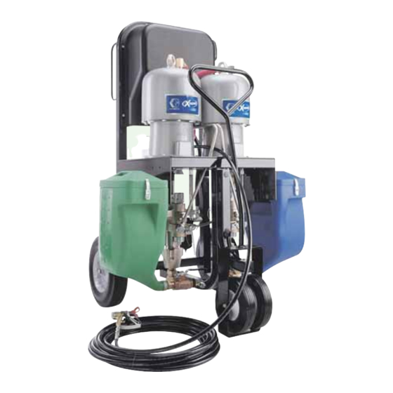
Xtreme Mix
Plural Component Mixer, OEM Unit
Important Safety Instructions
Read all warnings and instructions in this manual.
Save these instructions.
See page 4 for model information, including maxi-
mum working pressure and approvals.
Graco Inc. P.O. Box 1441 Minneapolis, MN 55440-1441
Copyright 2005, Graco Inc. is registered to I.S. EN ISO 9001
™
OEM
309521 rev.H
Advertisement
Table of Contents

Related Manuals for Graco Xtreme Mix OEM


Summary of Contents for Graco Xtreme Mix OEM
- Page 1 Read all warnings and instructions in this manual. Save these instructions. See page 4 for model information, including maxi- mum working pressure and approvals. Graco Inc. P.O. Box 1441 Minneapolis, MN 55440-1441 Copyright 2005, Graco Inc. is registered to I.S. EN ISO 9001...
-
Page 2: Table Of Contents
Operation and Repair ..... . 15 Graco Information ......32 Electrical Schematic . -
Page 3: Manual Conventions
Manual Conventions Manual Conventions Warning Caution WARNING CAUTION A caution alerts you to possible equipment damage or destruction if you do not follow instructions. A warning alerts you to possible serious injury or Note death if you do not follow instructions. Symbols, such as fire and explosion (shown), alert you A note indicates additional helpful information. -
Page 4: Xtreme Mix Oem Models
Xtreme Mix OEM Models Xtreme Mix OEM Models WARNING Do not install equipment approved only for non-haz- ardous location in a hazardous area. Substitution of components may impair intrinsic safety. See page 5. Approved for Hazardous Location Class I, Div 1, Group D... -
Page 5: Warning
Xtreme Mix OEM Models Warning Skin Injection Hazard High-pressure fluid from gun, hose leaks, or ruptured components will pierce skin. This may look like just a cut, but it is a serious injury that can result in amputation. Get immediate surgical treatment. - Page 6 Misuse can cause serious injury or death. • For professional use only. • Use equipment only for its intended purpose. Call your Graco distributor for information. • Read manuals, warnings, tags, and labels before operating equipment. Follow instructions. • Check equipment daily. Repair or replace worn or damaged parts immediately.
-
Page 7: Pressure Relief Procedure
Pressure Relief Procedure Pressure Relief Procedure 6. Hold a metal part of the gun firmly to a grounded WARNING metal pail. Trigger gun to relieve pressure. Follow Pressure Relief Procedure when you stop spraying and before cleaning, checking, servicing, or transporting equipment. -
Page 8: Assemble
Assemble Assemble 309521H... -
Page 9: Pumps And Sensors
Assemble Pumps and Sensors Control Box 1. Mount control box (3) to mounting plate (10). F . 1. • If using feed pumps, do not allow feed pressure to exceed 25% of spray pressure. a. Slide gasket (307) over back of pneumatic con- trol box (3), against lip. - Page 10 Assemble Key: Pump A Air Pneumatic Control Pump B Air Metering Valve Manifold Pump A Pilot Air 501 Pneumatic Valve Pump B Pilot Air 901 Air Filter Air Supply 902 Ground Wire Assembly Metering Valve A - CLOSE Ground manifold to true earth ground. Metering Valve A - OPEN Metering Valve B- CLOSE Ground by connecting ground wire from control box (3) to...
-
Page 11: Grounding
Assemble Grounding Standard Setup . 1 and F WARNING 1. Mount pneumatic control assembly (3) to mounting plate (10). F . 1. 2. Connect an air line (A and B) between each pneu- Read warnings, page 5, and follow instructions below. matic valve (501) and pump air motor inlet. -
Page 12: User Interface
Assemble User Interface 10 9 8 7 6 5 4 3 . 4 and F 1. Connect display board (410) communication cable (416) to J1 on main circuit board (301). 2. Connect data cable (406 - 7-pin connector) to J2. WARNING The user interface must be grounded. - Page 13 Assemble Cart-mounted 1. Secure metering valve assembly (6) to cart/stand with screws (913), washer (914), and nuts (915). . 1, page 8. 2. Connect fluid lines (provided by installer) between pumps and metering valves. 3. Cut air line tubing (included) to length needed to 919, 920 connect between metering valves (601) and sole- noid outlets.
- Page 14 Assemble 4. Screw ball valves (606, 611 - purchased separately) To calculate pressure loss: into fluid mix manifold (607). Pressure Loss = 0.000273 x Q x V L 5. Select appropriate fittings and fluid hose sizes and lengths to connect between fluid metering manifold Q = Flow (GPM) 15A898 and mix manifold (607).
-
Page 15: Proper Lifting
Proper Lifting Proper Lifting WARNING Follow instructions below to avoid dropping or swing- ing unit or being struck by the cart handle, which can cause serious injury or damage to equipment. Either remove the cart handle or secure it to the cart before lifting the unit. -
Page 16: Electrical Schematic
Electrical Schematic Electrical Schematic 15VDC Main Circuit Jumper (15V) Board 245705 Solenoids Metering Valve A Metering Valves Metering Valve B Pump A Air Motors Pump B Sensor BL-W 243678 BL-R BL-G Sensor BL-W 243678 BL-R BL-G Case Gnd Clip Key: BL Black BL-WBlack with white Shield... - Page 17 Electrical Schematic Air Input Power Power Supply Supply Barrier Board Front Panel Comport Pin Alarm + Front View Alarm COM COM Port RS232 Alarm 15A849 Connector Start Start/Stop Switch 15A851 Light Stop Display Board 245706 Key Switch 15A852 Key Switch momentary 309521H...
-
Page 18: Pneumatic Schematic
Pneumatic Schematic Pneumatic Schematic . 10 309521H... - Page 19 Pneumatic Schematic 309521H...
-
Page 20: Parts
Parts Parts Xtreme Mix Proportioner 908/909 918, 919, 920 309521H... - Page 21 Parts Xtreme Mix Proportioner Part Numbers Approved for Hazardous Location Approved for Non-hazardous Location (Class 1, Div 1, Group D) Xtreme Mix Pump (2) Plate (10) Xtreme Mix Pump (2) Plate (10) 233879 249274 (45:1) 246333 233871 249274 (45:1) 246332 233880 249275 (56:1) 246335...
-
Page 22: Pneumatic Control 245803
Parts Pneumatic Control 245803 Item 3, page 21 TO SOLENOIDS 306r FROM TURBINE POWER Ref. 304 TO PUMP POSITON SENSOR MOTOR A MOTOR B B PUMP A PUMP 309521H... - Page 23 IS = intrinsically safe 306g 160701 • ELBOW, street; 1/8 npt(m x f) Alternator bearing repair kit 223688 available. 306h 108190 • GAUGE, ‡ Not available for order from Graco. 306j‡ • GASKET, neoprene ★ Order length needed from distributor.
-
Page 24: User Interface 245804
418‡ WASHER 15C335 KNOB 107232 SET SCREW 15A850 WIRE HARNESS, data port ‡ Not available for order from Graco. 15A852 WIRE HARNESS, key switch Alarm Code Labels 409* LABEL, alarm code Item 409, English provided. To order other languages: 245706 CIRCUIT BOARD Part No. -
Page 25: Pump Air Manifold 245802
Parts Pump Air Manifold 245802 Item 5, page 21 Ref. Part No. Description Qty. C59752 VALVE, 3-way 108307 ELBOW; 3/4 npt 101689 PRESSURE GAUGE 112166 SCREW; 1/4-20 UNC 15A820 MANIFOLD 15A821 PLATE, direction 117332 REGULATOR 100840 ELBOW; 1/4 npt 15A819 MANIFOLD BLOCK 160032 NIPPLE;... -
Page 26: Metering Valve Manifold 245824
Parts Metering Valve Manifold 245824 Item 6, page 21 918c Ref. 918h Part No. Description Qty. 918g 245846 METERING VALVE; page 27 918d 606 (A side) 245861 SHUTOFF VALVE; see manual 918f 611 (B side) 306861 918b 245833 FLUID MANIFOLD; page 28 918e 918a 245860 SHUTOFF VALVE;... -
Page 27: Metering Valve 245846
Parts included in kit 234098. 111040 LOCKNUT, nylon; 5/16 UNC-3B † Parts included in kit 234131. 632* O-RING, nitrile † Not available for order from Graco. ‡ ▲ 633* O-RING, nitrile Replacement Warning labels available at no cost. † 634* O-RING, nitrile †... -
Page 28: Fluid Manifold 245833
664* SEAT 116343 GROUND SCREW,; M5 x 0.8 665* 103341 O-RING, PTFE 159239 NIPPLE; 3/8 x 1/2 npt 666* BALL, metallic 667* 117333 SPRING Parts included in kit 234100. PLUG; 3/8 npt ‡ Not available for order from Graco. 309521H... -
Page 29: Sensor 245825
Parts Sensor 245825 Item 7, page 21 716† 712† 704† 703† 720† †714 710* †701 709* 702* †707 705* 719* 713* †706 721* 711* †708 Ref. Ref. Part No. Description Qty. Part No. Description Qty. 712† 15A817 NUT; 1/8 npt 701†... -
Page 30: Technical Data
Technical Data Technical Data Mix ratio range ....... . . 0.0:1-10:1 (in 0.1 increments) Ratio tolerance range . - Page 31 Technical Data 309521H...
-
Page 32: Graco Standard Warranty
With the exception of any special, extended, or limited warranty published by Graco, Graco will, for a period of twelve months from the date of sale, repair or replace any part of the equipment determined by Graco to be defective.
Need help?
Do you have a question about the Xtreme Mix OEM and is the answer not in the manual?
Questions and answers