Table of Contents
Advertisement
Quick Links
Instructions – Parts List
P
RECISION
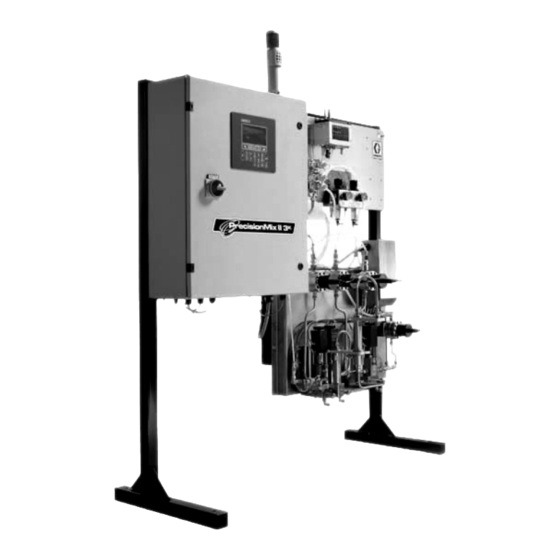
3K System
For Proportional Mixing of Two and Three Component Coatings
Patent No. 5,368,059
Read warnings and instructions.
See page 2 for the
Conforms to ANSI/UL
standard 2279
Class 1 Zone 0
R
AExia II A T4
110474
Certified to CAN/CSA
22.2 No. E79–11
0359
EEXia II A T3
II 2 G
ITS03ATEX21382
GRACO INC. P.O. BOX 1441 MINNEAPOLIS, MN 55440-1441
Copyright 2001, Graco Inc. is registered to I.S. EN ISO 9001
M
IXr II
Table of
Contents.
309107E
Advertisement
Table of Contents
Troubleshooting

Related Manuals for Graco PrecisionMix ii


Summary of Contents for Graco PrecisionMix ii
- Page 1 Class 1 Zone 0 AExia II A T4 110474 Certified to CAN/CSA 22.2 No. E79–11 0359 EEXia II A T3 II 2 G ITS03ATEX21382 GRACO INC. P.O. BOX 1441 MINNEAPOLIS, MN 55440-1441 Copyright 2001, Graco Inc. is registered to I.S. EN ISO 9001...
-
Page 2: Table Of Contents
2–4 Pressure Test Component B and C ..3–36 How the PrecisionMix II 3K Works ..2–6 Pressure Test the Solvent Lines .. - Page 3 ....... . . 8–6 PrecisionMix II 3K Robotic Interface ..
- Page 4 Table of Contents Troubleshooting ......10–1 Parts ........12–1 Revision Number .
- Page 5 ..13–15 Part No. 241647 Catalyst Change Kit 12–34 Set PrecisionMix II Date and Time ..13–16 Part No. 195048 Paint Shield ..
-
Page 7: Warnings
Warnings Warnings 1–1... - Page 8 1–2 Warnings...
- Page 9 WARNING FIRE, EXPLOSION, AND ELECTRIC SHOCK HAZARD Improper grounding, poor air ventilation, open flames, or sparks can cause a hazardous condition and result in fire or explosion and serious injury. D The PrecisionMix Controller must only be installed and serviced by a qualified electrician. D The PrecisionMix Controller is for use only in non-hazardous locations.
- Page 10 D This equipment is for professional use only. D Read all instruction manuals, tags, and labels before operating the equipment. D Use the equipment only for its intended purpose. If you are uncertain about usage, call your Graco distributor. D Do not alter or modify this equipment. Use only genuine Graco parts and accessories.
-
Page 11: Overview
Overview Overview 2–1... - Page 12 2–2 Overview...
-
Page 13: Using This Manual
This symbol alerts you to the possibility of serious injury or death if you do not follow the instructions. 2. Overview: This section provides information on Caution Symbol the instruction manuals and on PrecisionMix II 3K Component ID and function. CAUTION 3. Installation: This section provides information on installing a configured PrecisionMix II 3K system. -
Page 14: Related Publications
Related Publications Form No. Description Form No. Description 308288 Fluid Manifold Manual 308291 HP Color Change Valve Manual 308778 G3000 Meter Manual 309227 Gun Flush Box Manual 309148 Piston Meter Manual 308818 Printer Manual 309149 Magnetic Meter Manual 308292 Fluid Pressure Regulator 307731 LP Color Change Valve Assy. - Page 15 Overview 2–5...
-
Page 16: How The Precisionmix Ii 3K Works
Other inputs and outputs are provided to control the purging process, signal an alarm, and interface with The standard Graco PrecisionMix II 3K can blend most the operator. Refer to Fig. 3.21, page 3–29. two and three component epoxy or polyurethane paints. -
Page 17: Functional Diagrams
How the PrecisionMix II 3K Works Functional Diagram – Component A Dispense Component A Component C Component B TI0085B Fig. 2.2 KEY for Figs. 2.2, 2.3, and 2.4 Component A Component C Component B Supply Line, Component A Supply Line, Component C... - Page 18 How the PrecisionMix II 3K Works Functional Diagram – Component B Dispense Component A Component C Component B TI0087 Fig. 2.3 4. The controller sends a signal to activate the sole- 5. The component B dispense valve (G ) opens and...
- Page 19 How the PrecisionMix II 3K Works Functional Diagram – Component C Dispense Component A Component C Component B TI0086B Fig. 2.4 6. The component C dispense valve (G ) opens and 9. The three components continue to be alternately Component C flows into the first integrator cham- fed into the integrators as long as the gun is trig- ber.
-
Page 20: Changing The Mixing Order
6. Turn the tubes of both meters 180_ so the nuts face in the opposite direction. To convert the PrecisionMix II 3K to a configuration where Component A is mixed with Component B 7. Reinstall the Component B and C meters, in the before Component C is added, perform the following opposite locations. - Page 21 Changing the Mixing Order Before Changing Component B and C Tubing Connections C AP BP CP Detail of Solenoid Box After Changing Component B and C Tubing Connections TI0227 Fig. 2.6 Overview 2–11...
-
Page 22: Flow Control Overview
Flow Control Overview Flow Control is used to limit the flow of material to the System Requirements air spray gun to help avoid sags and runs in the finish The fluid feed system must have adequate volume and due to coatings being applied too thick or quickly and pressure to supply the air spray gun. -
Page 23: One Gun Flow Control Using A Flow Meter In The Mixed Material Line
Using a flow meter in the mixed material line, rather than monitoring fluid flow with the component A, B, and C flow meters, provides a faster response to changes in the flow rate setpoint. PrecisionMix II 3K Controller Panel User Interface with Color Change RS–485... -
Page 24: Flow Control Components
PrecisionMix II 3K Controller The controller can be configured to control and display the fluid control information, including setpoint, actual flow, milli-amp output values to the I/P transducer, system parameter, and I/O conditions. -
Page 25: Flow Control Parameters
Flow Control Overview Flow Control Parameters (Refer to Fig. 2.9) Example – If the setpoint is 500 cc/min. and the low limit is 100 cc/min.: The following flow control parameters are entered from either the User Interface or from digital input: The flow control will stop making adjustments when the flow rate falls below 400 cc/min. -
Page 26: Using Recipes/Color Change
Using Recipes/Color Change There are three modes of operation relating to the A color change may be performed with the operator changing of recipes: No Color Change, Integrated switch in the Mix or Standby position. If the Color Change, and Integrated Color Change with Queue. -
Page 27: Integrated Color Change With Queue
Using Recipes/Color Change Integrated Color Change – continued Special Outputs 1, 2, 5, and 6: The special outputs are optional outputs that the user can configure for their particular application. Each of these valves can The devices that are controlled by the Integrated Color be turned on and off up to four times during a color Change Sequences are as follows. -
Page 28: Color Change Sequences
Using Recipes/Color Change Color Change Sequences The color change sequence begins by closing all of the color change valves. Then the dump valve for Compo- There are four color change sequences that can be set nent A (resin) will immediately open, as well as the up to control how a color change will operate. -
Page 29: Changing From One Color Change Sequence To Another
Using Recipes/Color Change Changing from One Color Change Sequence to Another Transition Point Output Color Stack Solvent Dump Valve Component A It is possible to perform a color change from a recipe Component A Closes associated with one color change sequence to a recipe Color Stack Solvent Dump Valve Component B that is associated with another color change sequence. -
Page 30: Actual Valve Times
Using Recipes/Color Change Changing from One Color Change Actual Valve Times Sequence to Another – continued Actual valve times: Purge time = 20 seconds Mix time = 40 seconds Component A Dump time = 8 seconds Component A Solvent time = 5 seconds Special 1 on time = 0 seconds Special 1 time = 20 seconds Special 2 on time = 20 seconds... -
Page 31: Installation
Installation Installation 3–1... - Page 32 3–2 Installation...
-
Page 33: Typical Installation
D The Typical Installations shown in Figs. 3.1 and 3.2 are only a guideline for selecting and installing system components and accessories, and are not an actual system design. Contact your Graco distributor for assistance. KEY for Figs. 3.1 and 3.2 NOTE: The typical installation drawings (Figs. -
Page 34: Non-Intrinsically Safe
Typical Installation NON-INTRINSICALLY SAFE Component B Component C Solenoid Air Atomizing Air Component A Purge Air Resin Dump Operator Station Cable Fig. 3.1 3–4 Installation... -
Page 35: Intrinsically Safe
Typical Installation INTRINSICALLY SAFE Component B Component C Solenoid Air Atomizing Air Component A Purge Air Resin Dump Operator Station Cable Fig. 3.2 Installation 3–5... -
Page 36: Fluid Supply Requirements
If necessary, install pressure regulators on the fluid deliver a flow rate 1.5 times the maximum desired flow inlets to the PrecisionMix II 3K to reduce the fluid rate. supply pressure. Contact your Graco distributor for information on fluid pressure regulators. -
Page 37: Mounting Components
Depth: 3.25 in. 6 in. with the system, the parts were mounted to the stand (83 mm) (152 mm) at Graco. The Gun Flush Box can be wall, stand, or drum mounted in the spray booth. 6 in. 8 in. NOTE:... - Page 38 Mounting Components For Wall Mounting – continued Remote User Interface Depth: 3.75 in. Remote User Interface: If a remote User (95 mm) Interface is used, mount it at a convenient 12 in. (305 mm) location for the operator to view and use. 9 in.
-
Page 39: Stand Mounting Kit 241501
Mounting Components Stand Mounting Kit 241501 2. Drill holes in the floor, using the mounting stand base as a template, and install anchors as needed. 1. Select the desired location for the mounting stand. Be sure to leave sufficient space around the equipment for operator access, routing of hoses and cabling, and ventilation. -
Page 40: System Installation
NOTE: D All options ordered on configured systems are electrically tested at the factory and shipped con- nected from Graco. D It is recommended that all cables routed in the spray booth and high traffic areas be enclosed in conduit to prevent damage from paint, solvent, and traffic. -
Page 41: Power Requirements
System Installation Power Requirements 1. Purchase one rated for the desired input voltage (120 Vac or 220 Vac). The Precision Mix II control is designed to operate with 120 Vac or 220 Vac input power. See Fig. 3.8 for the wiring connections. -
Page 42: Install The Fluid Panel With Fluid Meters
System Installation Install the Fluid Panel (Code E) with Fluid 2. In certain situations, the cable (C6) may need to be disconnected and reconnected to route the Meters (Code F) cable as desired. If this is necessary follow the A non-intrinsically safe fluid panel (Code E–1) is avail- steps below and refer to the Electrical Connec- able for installing in a non-hazardous area. -
Page 43: Install The Air Control Kit
System Installation Install the Air Control Kit Be sure the supplied cable (C5) can reach the Preci- sionMix II 3K controller (B). 100 ft. (30.5 m) of cable is If you have ordered the color change, the air control kit supplied, pre-connected to the operator station. -
Page 44: Install The Color/Catalyst/Reducer Change Valves And Solenoids
System Installation Install the Color/Catalyst/Reducer Change 2. Power (P) and network (N) cables, connecting the color change panel with the controller (B), are Valves and Solenoids (Code K and L) installed at the factory. The cables are 50 ft. If color/catalyst/reducer change valves are ordered, (15.2 m) long. - Page 45 System Installation Install the Color/Catalyst/Reducer Change Valves and Solenoids (Code K and L) – continued Stack No. 2 and 3 Stack No. 1 Color Change Panel Solenoid Bank Solenoid Bank Splitter Component C Component A Stack No. 2 Color Change Valve Stack Component B Stack No.
-
Page 46: Install The Gun Flush Box And Solenoid Box
System Installation Install the Gun Flush Box and Solenoid Box (Code M, N and P) NOTE: 4. Electrically interlock the Gun Flush Box air supply D See Gun Flush Box Manual 309277 for gun flush with the ventilators to prevent the box from operat- ing when ventilating fans are not operating. - Page 47 System Installation Install the Gun Flush Box and Solenoid Box (Code M, N and P) – continued 8. Connect another air line (A1) from the atomizing air shutoff valve (L) to port S on the gun flush box. See Fig. 3.15. 9.
- Page 48 System Installation Install the Gun Flush Box and Solenoid Box (Code M, N and P) – continued Non-Hazardous Area Hazardous Area (mounted to the To Gun back of the fluid panel solenoid box) 8990A One Gun Flush Box Installation Fig. 3.17 3–18 Installation...
- Page 49 System Installation Install the Gun Flush Box and Solenoid Box (Code M, N and P) – continued Wire the second air flow switch through terminal block #11 in the solenoid box of the fluid panel. Non-Hazardous Area Hazardous Area Hazardous Area (mounted to the Non-Hazardous Area back of the fluid...
-
Page 50: Install The Optional Flow Control
System Installation Install the Optional Flow Control Fluid Connections NOTE: Refer to the system electrical schematic, Figs. 3.1 and 3.2. Manual 309138, included with the system. 1. Connect the solvent supply line to the solvent inlet 1. See Fig. 3.20. Install the fluid regulator (K) in the on the fluid panel. -
Page 51: Digital Outputs
System Installation Digital Outputs Terminal Description Non–Integrated Color Change Function ntegrated Color Change Function Block 5171 Solvent A Valve The Solvent A Valve output opens the solvent valve for Same as Non–Integrated Color Change. purging. This valve is typically used with air. 5181 Solvent B Valve The Solvent B Valve output opens the solvent valve for... -
Page 52: Component Electrical Connections
Component Electrical Connections Terminal Accessory/Option Cable Wire Color Function Barriers Barriers Accessory Terminal Strip No. in Name Part Uncon- Controlled Main Con- trolled Side troller Side Color Change Festo Solenoid Stack 2041 Festo solenoid bank 115153 Blue Can Low 2051 Network communication Shield Shield... - Page 53 Component Electrical Connections Terminal Accessory/Option Cable Wire Color Function Barriers Barriers Accessory Terminal Strip No. in Name Part Uncon- Controlled Main Con- trolled Side troller Side Solenoids 4021 Component A Brown Signal 4021 1082 Black Common 1082 1082 Drain Shield PA/gnd Shield 4061...
- Page 54 Component Electrical Connections Terminal Accessory/Option Cable Wire Color Function Barriers Barriers Accessory Terminal Strip No. in Name Part Uncon- Controlled Main Con- trolled Side troller Side Meters 4251 Component A White/Red Signal 4251 1082 Black Ground PA/gnd 1082 2021 24 VDC 2021 1082 Drain...
- Page 55 Component Electrical Connections Terminal Accessory/Option Cable Wire Color Function Barriers Barriers Accessory Terminal Strip No. in Name Part No. Uncon- Controlled Main Con- trolled Side troller Side Alarm 6171 From Gray Ratio alarm Gray wire Alarm 6201 Orange Potlife alarm Orange wire 1082 Yellow...
- Page 56 Component Electrical Connections Terminal Accessory/Option Cable Wire Color Function Barriers Barriers Accessory Terminal Strip No. in Name Part Uncon- Controlled Main Con- trolled Side troller Side Field Wiring Terminals for Additional Inter- face Capabilities 7121 Security bypass Input +24 VDC discrete 7111 Spare Input +24 VDC discrete...
- Page 57 Component Electrical Connections Terminal Accessory/Option Cable Wire Color Function Barriers Barriers Accessory Terminal Strip No. in Name Part Uncon- Controlled Main Con- trolled Side troller Side Field Wiring Terminals for Additional Inter- face Capabilities (continued) 6091 External process con- Flow control override Input +24 VDC discrete troller 6071...
- Page 58 Notes 3–28 Installation...
-
Page 59: Controller Terminal Block
Controller Terminal Block CAUTION If power and grounding connections are not done properly, the equipment will be damaged and the Network SHLD warranty will be voided. Network B Network A Refer to Fig. 3.21. RSM B* RSM A* RSM*/Festo +24V RSM*/Festo GND CAN_H CAN SHLD... -
Page 60: Ground The System
Object Being Sprayed Ground the object according to your local code. PrecisionMix II 3K Manifold The mounting surface for the PrecisionMix II 3K man- All Solvent Pails Used When Purging ifold must be electrically connected to the same true Ground the solvent pails according to your local code. -
Page 61: Check The Resistance
Check the Resistance Have a qualified electrician check the resistance WARNING between each PrecisionMix II 3K component and the true earth ground. The resistance must be less than 1 FIRE, EXPLOSION, AND ELECTRIC ohm. If the resistance is greater than 1 ohm, a different SHOCK HAZARD ground site may be required. -
Page 62: Power-Up Checklist
Power-up Checklist Power-up Steps PrecisionMix II 3K System Make sure the Operator Station switch is in STANDBY before turning on the system. 1. Ensure that the jumper position on the 24 VDC power supply is in the correct position for the main supply voltage. - Page 63 Power-up Checklist Step # 4 Interface Step #5 Step #6 Step #7 Step #10 Fig. 3.23 Installation 3–33...
-
Page 64: Checking Flow Control I/P Transducers
Flow Control Menu (FCMenu) NOTE: Only follow this procedure if a Flow Control system is installed. 1. Turn on the main power on the PrecisionMix II 3K controller. 2. Turn off the air supply to the I/P transducers. W ARNING The next test will use free-flowing air from the I/P transducer. -
Page 65: Testing Flow Control External 4-20 Ma Input Signal
Power-up Checklist Testing Flow Control External 4–20 mA 2. Vary the 4–20 mA signal and note the value changes on the screen. Input Signal NOTE: Only follow this procedure if a Flow Control For a maximum flow rate setpoint of 2000 cc/min., system is installed. -
Page 66: Pressure Test And Solvent Flush Procedure
4. pressure of the lowest rated system component. See the instruction manuals With Color Change of the individual PrecisionMix II 3K components for 1. Supply solvent pressure to the solvent flush port of their maximum working pressures. the color stack. -
Page 67: Operation
Operation Operation 4–1... - Page 68 4–2 Operation...
-
Page 69: Pressure Relief Procedure
Pressure Relief Procedure 2. Relieve fluid and air pressure at the component WARNING and solvent feed pumps or pressure pots, as explained in their separate instruction manuals. INJECTION HAZARD The system pressure must be manually 3. Set the operator switch to MIX relieved to prevent the system from starting or spraying accidentally. -
Page 70: Operator Controls And Indicators
Alarm Light The controller activates the alarm light when the Operator Station PrecisionMix II 3K has stopped operating because of without Color Change Control an alarm condition. The type of alarm will display on Fig. 4.2 the user interface. - Page 71 Operator Controls and Indicators Color Change Control When a new recipe is selected using the arrow keys, The current working recipe can be modified using the two blinking periods appear on the display, indicat- arrow keys A " and the enter key ing the new recipe information has been input, but the on the enter key has not been pressed.
-
Page 72: User Interface
Operator Controls and Indicators User Interface The User Interface is a small terminal with a 16 x 40 the controller door or as a remote station that can be character display and a keyboard for entering setup mounted as desired. See page 3–13. The operation of parameters. -
Page 73: Operating Checklist
Box; and wash cans, are electrically grounded and the floor of the spray area is electrically conductive and grounded. The PrecisionMix II 3K was tested with light- weight oil. To prevent contamination of your fluids, thoroughly purge the system with solvent Fig. -
Page 74: Purging The Ratio Check Valves
Operation Purging the Ratio Check Valves 1. Relieve the system pressure. 2. Close Component A, B, and C fluid shut-off valves. WARNING See Fig. 4.6. PRESSURIZED EQUIPMENT HAZARD 3. Place a container under the Component B and C To avoid splashing fluid in the eyes when ratio check valve dispense tube. - Page 75 Operation Purging the Ratio Check Valves 10. Fully open the component A fluid shut-off valve, and open the component A ratio check valve – continued one-half to one full turn. 6. Press the manual override button (K) on the sol- vent solenoid valve, which is inside the Precision- 11.
-
Page 76: Purging The Precisionmix Ii 3K System
Operation Purging the PrecisionMix II 3K System Purge the system during initial startup, at the end of each workday, and before any break longer than the pot life of the fluid. WARNING FIRE AND EXPLOSION HAZARD Solvent may be used to purge all three components,... - Page 77 Operation Purging the PrecisionMix II 3K System NOTE: If necessary, adjust the purge sequence so that only one sequence is required. – continued 9. Release the gun trigger when the pressure is Standard System Purge Procedure relieved, and set the operator switch back to 1.
-
Page 78: Starting Production
4–3 whenever you: D are instructed to relieve the pressure, 6. Turn on the PrecisionMix II 3K main power switch. D stop spraying, The User Interface will display the first Run D check or service any of the system equipment, screen. - Page 79 Check or reset the air regulator in the atomiz- stop. Move the operator switch momentarily to ing air line. 10. Operation of the PrecisionMix II 3K is controlled by Purge , then back to Standby to clear the operation of the spray gun.
-
Page 80: Stopping Production
D are instructed to relieve the pressure, exceed the pot life, you must purge the mixing system. D stop spraying, See Purging the PrecisionMix II 3K System, page 4–10. D check or service any of the system equipment, D install or clean the spray tip. -
Page 81: Flow Control Operation
Operation Flow Control Operation b. Setpoint change from a large value (600 cc/min.) to a smaller value (400 cc/min.): Initial Setup D If the flow rate during the first 10 seconds 1. See page 8–16 for flow control setup. is below the new setpoint, increase the Gain Factor by 50. -
Page 82: Integrated Color Change
7. Set the Operator Station switch Mix to start spraying. NOTE: The first three PrecisionMix II 3K alarms will be reset by the controller to prevent nuisance alarms during flushing and loading. 4–16 Operation... - Page 83 Notes Operation 4–17...
-
Page 84: Printer Reports
Printer Reports The PrecisionMix II 3K can output reports to a printer Run Mode Report that is connected to the controller. The report will show To print the Run Mode Report with the User Interface, the PrecisionMix II 3K information available at the time you must be at one of the run mode screens, then the report was printed. -
Page 85: Recipe Report
Printer Reports Alarm Report Recipe Report To print the Recipe Report with the User Interface, you must be at the Recipe Setup Menu screen (refer to page 9–4), then press the print key. Recipe Setup Menu Screen The Recipe Report will list the setup information for the recipe selected for setup (in the screen above, this would be recipe 1). -
Page 86: System Setup (Configuration) Report
Printer Reports System Setup (Configuration) Report System Setup Report (continued) To print the System Setup Report with the User Inter- face, you must be at the System Configuration Menu screen (refer to page 8–3), then press the print key. System Configuration Menu Screen The System Setup Report will list the system configu- ration information. - Page 87 Printer Reports System Setup Report (continued) Operation 4–21...
-
Page 88: Job Totals Report
Printer Reports Job Totals Report Batch Totals Report To print the Batch Totals Report with the User Inter- To print the Job Totals Report with the User Interface, face, you must be at the Batch Totals screen (refer to you must be at the Job Totals screen (refer to page page 7–3), then press the print key. -
Page 89: Grand Totals Report
Printer Reports Grand Totals Report Alarm Report To print the Alarm Report with the User Interface, you To print the Grand Totals Report with the User Inter- must be at the Alarm History screen (refer to page face, you must be at the Grand Totals screen (refer to 6–6), then press the print key. - Page 90 4–24 Operation...
-
Page 91: Screen Map
Screen Map Screen Map 5–1... - Page 92 5–2 Screen Map...
- Page 93 Screen Map 5–3...
- Page 94 5–4 Screen Map...
-
Page 95: Run Monitor
Run Monitor Run Monitor 6–1... - Page 96 6–2 Run Monitor...
- Page 97 Run Monitor Screens Information Home Screen This is the HOME screen where you choose which system function to enter. D RUN MONITOR (#1) has the normal operating screens. D TOTALIZERS (#2) has the screens with information on material usage on the selected recipe. D RECIPE SETUP (#3) screens allow you to setup “recipes”...
-
Page 98: Flow Rate
Run Monitor Screens Information Flow Rate Flow rate is a real time display of how much flow is going through the system. It updates every two seconds and is a weighted average of the previous flow rate displays. The readings are taken by the Component A, B, and C fluid meters. -
Page 99: Flow Rate Setpoint
Run Monitor Screens Information RM4A Flow Rate Setpoint Flow control can only be used with the proper hard- ware installation. The Flow Rate Setpoint screen only appears if flow control is turned on. It shows the flow control Setpoint and the Actual flow rate. The mA reading for Analog out and Setpoint in is converted to a pneumatic signal, which is applied to a fluid pressure regulator to open the regulator a certain... -
Page 100: Alarm History
Run Monitor Screens Information Alarm History The alarm history screen displays the last 10 alarms that have occurred. See the alarm descriptions on page 10–7. The most recent alarm will appear at the top of the screen. This screen does not ever completely clear. There is a maximum of 10 alarm lines that can display. -
Page 101: Integrated Color Change With Queue
Run Monitor Screens Information RM7A Integrated Color Change with Queue This screen only appears if Integrated Color Change with Queue is turned on. Integrated color change with queue is generally used with an automated system where there is a set job sequence to be performed. The queue parameters override the normal color change parameters during the color change. -
Page 102: Modify Queue Screen
Run Monitor RM7B Modify Queue Screen This screen is used to make modifications to the existing queue. Zero is not a valid entry for A–comp, B–comp, C–comp, or Sequence. If zero is entered for any of these parameters, color change will not occur. -
Page 103: Totalizers
Totalizers Totalizers 7–1... - Page 104 7–2 Totalizers...
-
Page 105: Home Screen
Totalizers Screens Information Home Screen Selecting #2 on the Home Screen will bring up the first Totalizers screen (T1 – Select Recipe and Totalizer Screen). The totalizers screens allow you to monitor the amount of fluid that has gone through the individual meters in the system for a particular recipe. -
Page 106: Job Totals
Totalizers Screens Information Job Totals The Job Totalizers are resettable. They keep a running total in cubic centimeters or ounces of the fluid dis- pensed until the totals are cleared by pressing the cancel X key. Solvent SOLVENT will only appear if the system was configured to use a solvent valve. -
Page 107: Grand Totals
Totalizers Screens Information Grand Totals The Grand Totalizers are not resettable. They keep a running total in liters or gallons of the fluid dispensed. Solvent See the Solvent information on previous page. A + B + C Dump See the A + B + C Dump information on previous page. - Page 108 7–6 Totalizers...
-
Page 109: System Configuration
System Configuration System Configuration 8–1... - Page 110 8–2 System Configuration...
-
Page 111: Home Screen
System Configuration Screens Information Home Screen Selecting #4 on the Home Screen will bring up the Password Screen, if a password is required, or the System Configuration Menu screen if no password is required. The System Configuration screens allow you to setup the controller to operate according to your system requirements. -
Page 112: Menu Screen
System Configuration Screens Information Menu Screen (CMENU) This is the SYSTEM CONFIGURATION MENU screen where you can access the system configuration parameters. D Any selections made during configuration are globally applied to all recipes. D When an entry is accepted by the system, the value will be highlighted. -
Page 113: Language
IMPORTANT! When switching from one language to another you must cycle power. Power down the PrecisionMix II and restart. The new language will be displayed. Type the number for the desired language, then . -
Page 114: Display Units Of Measurement
System Configuration Screens Information Display Units of Measurement Select the units of measurement you want the screens to display. The TARGET/ACTUAL display will not show ounces on the Run Monitor #1 screen. The dis- play is fixed for cubic centimeters. See page 6–3. -
Page 115: Potlife Timer
System Configuration Screens Information Potlife Timer You can turn the potlife timer off or activate it and choose one of the three possible system responses to the alarm. The system must have a dump valve or gun flush box installed to use selection #4. A sepa- rate output Gun Trigger 1 Auto/Dump Terminal Block #5211 or #5221, based on the number of the gun selected, is provided to actuate the... -
Page 116: Solvent Meter
System Configuration Screens Information Solvent Meter You can turn the input to the solvent meter off or on. Select #1 if a solvent meter is not installed in the system. Select #2 if a solvent meter is installed in the system. -
Page 117: Purge Sequence: Purge Alarms
System Configuration Screens Information C8B: Purge Sequence: Valves Select the valve you want the purge sequence to start and end with. Typically start with Purge Valve A and end with Purge Valve C. D If 1 Purge Valve was selected in the previous purge sequence screen, only Purge Valve A will appear as a choice. -
Page 118: Mixed Load Volumes
System Configuration Screens Information Mixed Load Volumes The Mixed Load Volume is the amount of material needed to evacuate the solvent from the hose and gun. D If color change is off, the load volume activates after a complete purge and will then turn on the gun trigger output for the volume entered. -
Page 119: Mix/Purge
System Configuration Screens Information Turning the gun flush boxes on or off will enable or The features related to the gun flush boxes are the disable the features related to the gun flush boxes and potlife autodump, the mixed load volume, and the the purge/load interlock. -
Page 120: Integrator Volume
System Configuration Screens Information C13: Integrator Volume Select the total volume to dispense for each compo- nent A, component B, and component C cycle. A typical setting is 50 cc. A setting greater than 50 cc requires a hardware change. Type the number for the integrator volume, then . -
Page 121: Time And Date Set
System Configuration Screens Information C16: Time and Date Set Use this screen to set time and date information. A date display format of month/day/year ( ) or day/month/year ( ) is available. Type the time and date information. Press after each entry. Type the number for the desired date display format. -
Page 122: Display Setup
System Configuration Screens Information C17: Display Setup Use this screen to set the User Interface display brightness and contrast and select a non-inverted (the default selection) or inverted display. Larger numbers increase the brightness and contrast. This screen also notifies you if the User Inter- face battery is running low. -
Page 123: Air Flow Switch
CA UTION IMPORTANT The accuracy of the PrecisionMix II 3K relies on a signal that the gun is being triggered. Failure to use a gun trigger signal will cause unpredictable perfor- mance which can result in off-ratio spraying and ruined finish on parts. -
Page 124: Flow Control Setup
Flow Control Setup Screens Home Screen Press key 4 , then Password Screen D This password screen only appears if the password is changed from the factory default of “0” (zero). If requested, type the password, then Menu Screen (CMENU) Type 12, for FLOW CONTROL, then 8–16 System Configuration... -
Page 125: Flow Control Options
Flow Control Setup Screens Information C12: Flow Control Options D Select #1, OFF, if flow control hardware is not installed on the system. Flow control cannot be used without the proper hardware. Refer to the Installation section. D If flow control is installed, select #2 or #3, depend- ing on whether you are using a hand gun or an automatic gun. -
Page 126: Source Of Flow Control Data
Flow Control Setup Screens Information FC1: Source of Flow Control Data Select the source for flow rate setpoint input. Flow Control and Setpoint D Selecting #1 will set the User Interface as the source of input. D Selecting #2 will set a network computer as the source of input. -
Page 127: Flow Control Force Output
Flow Control Setup Screens Information FC3: Flow Control Force Output The Force Analog Output screen can be used for troubleshooting. It enables you to manipulate the mA output to force the regulator open or closed. option is disabled (turned to OFF) when the screen is left. Select to turn the outputs ON or OFF, then . -
Page 128: Flow Control Meter Location
Flow Control Setup Screens Information FC5: Flow Control Meter Location D Select #1 if the component A, B, and C flow meters are being used to monitor fluid flow. D Selecting #2 if a fluid meter is installed in the mixed material line to monitor fluid flow. -
Page 129: Integrated Color Change Setup
Integrated Color Change Setup Screens Information Home Screen Press key 4 , then Password Screen If requested, type the password, then Menu Screen (CMENU) Type 14, for COLOR CHANGE, then System Configuration 8–21... -
Page 130: Color Change Mode Screen
Integrated Color Change Setup Screens Information Color Change Mode Screen Select or “ With , the tasks necessary to execute a color change are done automatically whenever a new recipe is selected. The color change sequence is a time-based mode of operation that can be configured by the user. -
Page 131: Color Change Graph Screen
Integrated Color Change Setup Screens Information ICC102: Color Change Graph Screen The functions will appear in the Color Change Graph in the order that they were previously entered. The graph takes time to update so wait for the update before going onto the next screen. -
Page 132: A Component Dump Timer Value
Integrated Color Change Setup Screens Information ICC2: A Component Dump Timer Value Total Sequence Time The total sequence time is automatically set by the addition of the purge start time, the purge duration time, and the mix duration time. In order to change Total Sequence Time, the purge and/or mix time must be changed in the previous screen. -
Page 133: B Component Dump Timer Value
Integrated Color Change Setup Screens Information ICC4: B Component Dump Timer Value B Component Dump Timer Value The time length the dump valve stays open must be defined during color change setup. The dump valve allows the unmixed B component materials to be dumped from the system before entering the mix manifold. -
Page 134: C Component Dump Timer Valve
Integrated Color Change Setup Screens Information ICC6: C Component Dump Timer Value C Component Dump Timer Value The time length the dump valve stays open must be defined during color change setup. The dump valve allows the unmixed C component materials to be dumped from the system before entering the mix manifold. -
Page 135: Gun 1 Trigger Start/Duration Times
Integrated Color Change Setup Screens Information ICC8: Gun 1 Trigger Start/Duration Times Gun Triggers 1–2 The gun triggers are electrical outputs that can be configured to turn on and off up to two times. These outputs are typically wired to the gun triggers on the Gun Flush Boxes or the operator’s gun control. -
Page 136: Special 1, 2, 5, And 6 Trigger Start/Duration Times
Integrated Color Change Setup Screens Information ICC10–13: Special 1, 2, 5, and 6 Trigger Start/Duration Times Special Triggers 1, 2, 5, and 6 The special triggers are optional outputs that the user can configure for their particular application. Each of the four outputs can turn valves on and off up to four times during a color change sequence. -
Page 137: Precisionmix Ii 3K Robotic Interface
I/O Timing high in recipe 0, an Invalid Recipe Alarm will occur The I/O system on the PrecisionMix II 3K needs 200 (recipe 0 is not a valid recipe for mixing). ms to process and I/O change. For this reason, it is a... -
Page 138: Integrated Color Change
PrecisionMix II 3K Robotic Interface Integrated Color Change TI0494 Fig. 8.1 8–30 System Configuration... -
Page 139: Non-Integrated Color Change
PrecisionMix II 3K Robotic Interface Non–Integrated Color Change TI0494 Fig. 8.2 Note: When purging through the I/O, there is a 2 second delay after the purge signal goes high before the purge actually begins. this delay allows time for resetting alarms or for relieving pressure in the system before the purge begins. -
Page 140: Digital Inputs
Integrated Color Change Function Block 5051 Gun Trigger 1 The Gun 1 Trigger input signals the PrecisionMix II 3K that Same as Non–Integrated Color spraying with the first gun is being attempted. This input is Change. typically wired to an air flow switch that signals when at- omization air is being sent to the gun. - Page 141 PrecisionMix II 3K Robotic Interface Digital Inputs Terminal Description Non–Integrated Color Change Function Integrated Color Change Function Block 6051 Purge The Purge input is used to trigger a purge of the sys- Same as Non–Integrated Color Change. tem. The purge will be initiated after a 2 second delay.
- Page 142 8–34 System Configuration...
-
Page 143: Recipe Setup
Recipe Setup Recipe Setup 9–1... - Page 144 9–2 Recipe Setup...
-
Page 145: Home Screen
Recipe Setup Screens Information Home Screen D RECIPE SETUP (#3) screens allow you to setup “recipes” (ratio programs) for a variety of fluids. Press key 3 then Password Screen D This password screen only appears if the password is changed from the factory default of “0” zero. D After the password is entered the system remains unlocked for 5 minutes allowing the user to navi- gate all screens without further password prompt-... -
Page 146: Recipe Selection
Recipe Setup Screens Information S101: Recipe Selection Enter a number between 0–63 to assign to the recipe being configured. Keep a record of the recipes you have entered. The number of recipes available are set during system configuration. Refer to page 8–6. Recipe 0 is the global recipe. -
Page 147: Setup Menu With Integrated Color Change On
Recipe Setup S102: Setup Menu with Integrated Color Change On (with or without Queue) and Flow Control On Recipes allow you to store ratio programs for various materials or job requirements. After setup, the recipes are selected for use on an outside source, such as the User Interface. -
Page 148: Mix Ratio And Tolerance
Recipe Setup Screens Information Mix Ratio and Tolerance Mix Ratio Enter the volumetric mix ratio of component A to component B and for component C to component B. The value of Component B is set at 1 and cannot be adjusted. -
Page 149: Color Change Sequence
Recipe Setup Screens Information If Integrated Color Change is On (with or without Queue) Color Change Sequence Flush/Fill Sequence Number (1–4) The flush/fill sequences were set up during system configuration. Refer to the Integrated Color Change Sequence screen on page 8–22. A Color Valve (1–10) Select the color valve to open for the Component A material desired. -
Page 150: Purge Sequence
Recipe Setup Screens Information If Integrated Color Change is Off Purge Sequence Purge Time If the Integrated Color Change is turned off, the purge sequence needs to be setup manually for each recipe, using the PURGE SEQUENCE screen. Which purge valves appear for setup depends on the number of valves selected during system configura- tion. -
Page 151: System Alarms With Flow Control On And Hand Gun Selected
Recipe Setup Screens Information System Alarms with Flow Control On and Hand Gun Selected Gun Potlife Time Limit Sets the maximum time allowed for mixed fluid to be in the system before tripping a pot life alarm. The timer starts when catalyst is introduced into the integrator. Follow the material recommendation when setting a value. -
Page 152: System Alarms With Flow Control On And Automatic Gun Selected
Recipe Setup Screens Information System Alarms with Flow Control On and Automatic Gun Selected Gun Potlife Time Limit See previous screen information. Gun Potlife Timer Reset See previous screen information. Flow Rate Alarm Tolerance The flow rate alarm output will be on when the actual flow rate falls out of this tolerance for three consecu- tive seconds. -
Page 153: Meter Calibration Tests
Recipe Setup Screens Information Meter Calibration Tests The Meter Calibration Tests screen is used to select which flow meter to calibrate individually or to do a mixed material calibration. D Selection 4, will only appear if a solvent meter was selected during system configuration. -
Page 154: Component A Flow Meter Calibration
Recipe Setup Screens Information S401 Component A Flow Meter Calibration Selection 1, 2, 3, and 4 (Selection 1 shown at left, Selections 2–6 on the following pages) The existing Flow Meter K-factor will appear in the first field. A new K-factor can be entered in this field. The flow meter size must be entered in cubic centime- ters per electrical pulse. -
Page 155: Component B Flow Meter Calibration
Recipe Setup Screens Information S402 Component B Flow Meter Calibration Selection 2 See the description on page 9–12. S403 Component C Flow Meter Calibration Selection 3 See the description on page 9–12. Recipe Setup 9–13... -
Page 156: Solvent Flow Meter Calibration
Recipe Setup Screens Information S404 Solvent Flow Meter Calibration Selection 4 See the description on page 9–12. S405 Mixed Material Calibration Screen Selection 5 This screen is used to do a mixed material calibration, which can be the most accurate method of calibrating the component A, B, and C meters. -
Page 157: Gun 1 Meter Calibration
Recipe Setup Screens Information S406 Gun 1 Meter Calibration Selection 6 See the description on page 9–12. Recipe Setup 9–15... -
Page 158: Setup Flow Control
Recipe Setup Screens Information Setup Flow Control Purge Override Setpoint Sets the percentage to open the fluid regulator during a purge cycle. Generally use a setting of 100% to allow maximum fluid flow. Fill Override Setpoint Sets the percentage to open the fluid regulator during a fill cycle. -
Page 159: Gain Factor Graphs
Recipe Setup Gain Factor Graphs The following examples of gain factors are based on Gain = 1000 switching between a setpoint of 200 cc/min. to 400 Faster setpoint transition but greater overshooting of cc/min. and back to 200 cc/min. A preferred gain factor the new setpoint. -
Page 160: Flow Meter Calibration Procedure
Flow Meter Calibration Procedure Selection 1, 2, 3, or 4: Calibrating the Meters Individually NOTE: Take a large sample (1000 cc or more) of a fluid that is a known accurate weight per gallon so that any error in measuring the sample is spread out. WARNING PRESSURIZED EQUIPMENT HAZARD To avoid splashing fluid in the eyes when... - Page 161 To abort calibration, you can select STOP. 11. The screen will display the volume of fluid the PrecisionMix II 3K determined was dispensed in field, based on the pre- 14. Go to the next screen and repeat the process viously entered calibration factor.
-
Page 162: Selection 6: Calibrating The Gun 1 Meter
2. Enter selection 6, for the flow meter you want to 5. The screen will display the volume of fluid the calibrate. PrecisionMix II 3K determined was dispensed in field, based on the pre- viously entered calibration factor. 6. If the actual volume dispensed into the container is... -
Page 163: Selection 5: Mixed Material Calibration
Flow Meter Calibration Procedure NOTE: Take a large sample (1000 cc or more) of a 1. Make sure the operator switch is set at fluid that is a known accurate weight per gallon so that Standby any error in measuring the sample is spread out. CAUTION WARNING The Component A, B, and C fluid shut-off valves... - Page 164 C ratio check valve. Component A, B, and C and press the ENTER key The PrecisionMix II 3K will run and dispense the number of doses selected of component A, B, and NOTE: New values can be typed in or the toggle keys C into the separate beakers.
-
Page 165: Troubleshooting
Troubleshooting 10-1 Troubleshooting... - Page 166 10-2 Troubleshooting...
-
Page 167: Revision Number
Troubleshooting Reference Revision Numbers This screen displays the revision numbers for all electronic devices connected to the PrecisionMix II system. For any device that is not connected, or has a fault, the revision will be 0.00. The ModBus Receive Command value will increment every time the Preci- sionMix II system communicates with the computer that has the Graco’s Advance Material Reporting... - Page 168 Troubleshooting Reference Bottom View Bottom View COLOR CHANGE VALVE SOLENOIDS Fig. 10.1 Color #6 Rack #1, Solenoid Bank #1 Color #7 LED No. Function Color #8 Component A Solvent Color #9 Component A Dump Color #10 Color #1 Rack #2, Solenoid Bank #1 Color #2 LED No.
- Page 169 Troubleshooting Reference Mode Switch Module 1 Module 2 Module 3 INPUT OUTPUT MODULES TERMINAL BLOCK CONTROLLER Fig. 10.2 Module 1 Inputs Module 1 Outputs Function Terminal Function Terminal Block No. Block No. Gun 1 Trigger (Air Flow Switch) 5051 Solvent A Valve 5171 Gun 2 Trigger (Air Flow Switch) 5061...
- Page 170 Troubleshooting Reference Module 2 Inputs Module 3 Inputs Function Terminal Function Terminal Block No. Block No. Purge 6051 Recipe Bit 0 7051 6061 Recipe Bit 1 7061 Gun 1 Flow Control Reset Start 6071 Recipe Bit 2 7071 Gun 2 Flow Control Reset Start 6081 Recipe Bit 3 7081...
-
Page 171: Alarm Troubleshooting
Alarm Troubleshooting Output number #8 on module #2 will be high when any WARNING of the alarms occur. INJECTION HAZARD See page 10–5 for the location of the Con- To reduce the risk of a serious injury, troller modules inputs and outputs. follow the Pressure Relief Procedure on page 4–3 before checking or servic- ing the equipment. -
Page 172: Ratio Low Or Ratio High
Ratio Low A:B or C:B operating properly. The PrecisionMix II 3K has dispensed a cycle (A:B or C:B) at a mix ratio less than the ratio target plus the tolerance. Checking the Actuation of the Valves... -
Page 173: Dose Time A, B, Or C
Checking for a Meter or Cable Failure Manually open the catalyst, resin, or reducer dispense When the PrecisionMix II 3K is in the MIX mode and valve and trigger the gun into a grounded waste con- the air flow switch is closed, which indicates that the tainer. -
Page 174: Flow Rate Alarms For A System Without Flow Control
High/Low flow alarm output will be on Output #2 of equipment (such as fans and conveyors). Module #2. 3. Check to see if the PrecisionMix II 3K is reading Gun #2 High/Low Flow any fluid flow. High/Low flow alarm output will be on Output #3 of 4. -
Page 175: Purge/Load Interlock Not Ready
Alarm Troubleshooting Purge/Load Interlock Not Ready I/O Change Alarm output will be on Output #6 of Module #2. Alarm output will be on Output #6 of Module #2. This alarm occurs when a purge, color change, or mixed load sequence is attempted without satisfying the purge/load interlocks. -
Page 176: Display Battery Low
Controller battery. Follow the instructions for changing the battery on page 11–4. Restore the This alarm is generated when the user interface soft- memory with the PrecisionMix II Maintenance Utilities ware revision is different than the Precision Mix II software, provided with the system. -
Page 177: Warnings
Alarm Troubleshooting WARNINGS Grand Total Rollover The Grand Total Rollover warning indicates that the Warnings are different from alarms in that they do not grand totals have been reset to zero, which will occur turn on the Operator Station alarm light, appear as a popup message on the User Interface, or cause a when the totals exceed 380,000 liters (100,396 gal- Controller action (such as shutting off the system). -
Page 178: Solenoid Box Troubleshooting
Solenoid Box Troubleshooting The troubleshooting chart below will help you locate Electrical Failure and solve a problem with the fluid panel solenoid box. If there is an electrical failure, push the solenoid manu- al button (K) on the Solvent C Purge valve while WARNING triggering the gun to flush the system. - Page 179 SOLVENT PURGE PURGE SOLVENT RESIN SUPPLY MIX BLOCK BLOCK RESIN CATALYST REDUCER CATALYST RESIN FLOWMETER CATALYST FLOWMETER SUPPLY FLUID MANIFOLD REDUCER FLOWMETER AIR FLOW SWITCH #1 SPRAY DEVICE TI0239 PrecisionMix II 3K Fluid Panel Pneumatic Schematic Fig. 10.4 10-15 Troubleshooting...
-
Page 180: Gun Flush Box Troubleshooting
Gun Flush Box Troubleshooting AIR INLET AIR HOSE AA OUT AIR INLET SPRAY DEVICE GFB–S GUN FLUSH CONTROL BOX GFB–P GFB–A DOOR/GUN GUN FLUSH BOX MIXED MATERIAL HOSE Gun Flush Box Pneumatic Schematic Fig. 10.5 10-16 Troubleshooting... -
Page 181: Operator Station With Color Change Troubleshooting
Operator Station with Color Change Troubleshooting PROBLEM CAUSE SOLUTION Power is OFF. Turn ON power to the PrecisionMix II 3K. Nothing displayed. Faulty cable. Check or replace cable. Circuit board failure. Replace circuit board. Interface 321 module failure. Replace module with Part No. 114783. - Page 182 10-18 Troubleshooting...
-
Page 183: Service
Service 11-1 Service... - Page 184 11-2 Service...
-
Page 185: Replacing The User Interface Battery
If the battery fails or is not installed correctly, the User Interface setup memory could be lost. A copy of this setup is on the PrecisionMix II 3K Mainte- 7. Disconnect the power connector (A). nance Utilities software, which is on a CD, included with the system. -
Page 186: Replacing The Controller Battery
Install the battery door (K). system. 7. Turn off the power before connecting the cables. Changing the Battery 1. Back up the PrecisionMix II 3K configuration, using 8. Reconnect the communication cables. the Graco PrecisionMix II 3K Maintenance Utilities software. -
Page 187: Replacing Isolation Barrier Fuses
Service Replacing Isolation Barrier Fuses Replacing the User Interface 1. Turn the PrecisionMix II 3K power switch (D) to off. 1. Turn the PrecisionMix II 3K power switch (D) to off. See Fig. 11.3. See Fig. 11.3. 2. Open the controller door (E). -
Page 188: Replacing The Power Supply
Service Replacing the Power Supply Changing the Power Supply Voltage 1. Turn the PrecisionMix II 3K power switch (D) to off. To change the power supply voltage from 100–120 Vac See Fig. 11.3. to 200–240 Vac or the reverse, follow this procedure. -
Page 189: Servicing The Operator Station
P1 slot of the new circuit board aligns with the membrane switch. Secure the new 1. Turn the PrecisionMix II 3K power switch (D) to off. circuit board to the cover with the 4 screws (C). See Fig. 11.3. -
Page 190: Replacing Control Modules
Replacing Control Modules 6. Latch the mounting plate back in place in the controller. 1. Turn the PrecisionMix II 3K power switch (D) to off. See Fig. 11.3. 7. Remove the screws (K) from the modules (J) between the removed end plate and the module 2. -
Page 191: Replacing Control Submodules
Service Replacing Control Submodules 4021 4061 1. Turn the PrecisionMix II 3K power switch (D) to off. See Fig. 11.3. 4081 2. Turn off the main power to the PrecisionMix II 3K 2021 1082 controller. 3. Open the controller door. - Page 192 11-10 Service...
-
Page 193: Parts
Parts 12-1 Parts... - Page 194 12-2 Parts...
-
Page 195: Controller With User Interface
Parts Controller with User Interface Part No. 243540 Part No. 243541 Controller with Panel Mounted User Controller with Remote User Interface Interface (Shown) Ref. Part No. Description Qty. Ref. Part No. Description Qty. 240834 CONTROLLER, See page 12–4 for service parts 240834 CONTROLLER, See page 514030... -
Page 196: Controller
Parts Controller Part No. 240834 Controller Ref. Part No. Description Qty. Ref. Part No. Description Qty. 104029 GROUND CLAMP 114892 INSERTION BRIDGE, 2 position 111307 WASHER, lock, M5 115307 CONNECTOR, plug 110911 NUT, hex, M5 114894 FIXED BRIDGE BAR 112446 END BRACKET, universal 114929 CONNECTOR, plug... - Page 197 Parts 109, 110, 111 156, 157, 158 117, 125 117, 126 Detail A Detail B 122 120 TI0240 122 112 Detail C 8960A 12-5 Parts...
-
Page 198: Flow Control
CABLE 104165 FITTING, tube 830352 REGULATOR, fluid, quick flush 597151 FITTING, elbow (not shown) 590332 TUBING, 1/4” OD 239716 METER, GRACO G–3000 none 241799 CABLE ASSEMBLY none 115130 JUMPER CONNECTOR (not shown) none 194477 CABLE, 100 ft. (30.5 m) none 114885 MINI TERMINAL BLOCK, MBKKB 2.5 (not shown) - Page 199 Parts Flow Control 1g, 1n 1k, 1m 9003A Operator Stations 1 (see above) Controller Air in Air out TI0167 TI0169 12-7 Parts...
-
Page 200: Communication Ports
Parts Communication Ports Part No. 241379 Part No. 241378 Network/PC Port Accessory Kit Local Printer Accessory Kit Ref. Part No. Description Qty. Ref. Part No. Description Qty. 114780 MODULE, interface, RS232 193738 WIRE HARNESS, local 114783 MODULE, interface, RS485 printer 194544 WIRE HARNESS, network Keep these spare parts on hand to reduce down time. -
Page 201: Fluid Panel
Parts Fluid Panel Wall Fluid Panel, Non-intrinsically Safe Wall Fluid Panel, Intrinsically Safe Ref. Part No. Description Qty. Ref. Part No. Description Qty. 243493 FLUID PANEL MODULE, 243493 FLUID PANEL MODULE, See page 12–10 for service See page 12–10 for service parts parts SOLENOID MODULE, IS,... -
Page 202: Fluid Panel Module
Parts Fluid Panel Module Part No. 243493 Fluid Panel Module Ref. Part No. Description Qty. Ref. Part No. Description Qty. 192590 BRACKET, static mixer 196023 PLATE, fluid panel 513817 BULKHEAD, 3/8” tube x 1/4 243486 MANIFOLD, fluid, compo- npt(f) nent A and C; See manual 308288 for service parts 196087 TUBE, second stage... - Page 203 Parts 140, 141, 142 Y137 139Y See Detail at Left TI0226 113 112 146, 147, 148Y TI0168 Back Side 107 108 TI0175 12-11 Parts...
-
Page 204: Solenoid Module
Parts Solenoid Module Part No. 552184 Ref. Part No. Description Qty. Four Solenoid Module, Intrinsically Safe 114230 MANIFOLD, solenoid Part No. 552186 112698 ELBOW, 1/8 npt(m) x 1/4” Four Solenoid Module, Non-intrinsically O.D. tube 114263 CONNECTOR, 5/32 tube Safe 114421 CONNECTOR, strain relief, 0.170–0.470 Ref. -
Page 205: Fluid Meters
Parts Fluid Meters Part No. 243512 Part No. 243513 G3000t Meter Kit, for Components A, B, Piston Meter Kit, for solvent-borne and C (20–3000 cps) Components B and C (0.8–20 cps) Ref. Part No. Description Qty. Ref. Part No. Description Qty. -
Page 206: Part No. 243515
Parts Fluid Meters Part No. 243515 Meter Kit, for water-borne Component A (100–5000 cps) Ref. Part No. Description Qty. 551634 METER; for water-borne materials only 514629 SENSOR, flow meter 626204 PLATE, mounting 196086 TUBE, fluid 551903 SCREW, cap, socket head 105468 SCREW 6, 12... - Page 207 Notes 12-15 Parts...
-
Page 208: Air Supply Station
Parts Air Supply Station Part No. 570122 Air Supply Station Ref. Part No. Description Qty. (Ref) 551980 AIR REGULATOR ASSEMBLY 551974 WALL BRACKET (Ref) 103* 552137 CHECK VALVE, 1/4 npt(m) 504235 CONNECTOR, 1/4” OD tube x 1/4 npt(f) Keep these spare parts on hand to reduce down time. 3/8 npt Inlet 1/4”... -
Page 209: Operator Station
Parts Operator Station Part No. 240835 Operator Station for One Color Ref. Part No. Description Qty. Ref. Part No. Description Qty. 193733 LABEL 194477 CABLE, operator station, 100 ft. (30.5 m) 114760 LIGHT, indicator 194478 CABLE, operator station, 114761 BASE, light 200 ft. -
Page 210: Part No. 240877
Parts Part No. 240877 Operator Station with Color Change Ref. Part No. Description Qty. Ref. Part No. Description Qty. 193733 LABEL 194477 CABLE, operator station, 100 ft. (30.5 m) (not shown) 114760 LIGHT, indicator 194478 CABLE, operator station, 114761 BASE, light 200 ft. -
Page 211: Low Pressure Color Change Module
Parts Low Pressure Color Change Module Part No. 241386 2–4 Color, Low Pressure Module Includes items 1–15 Part No. 242025 2–4 Color, Low Pressure Module; Without color valves, mounting brackets or mounting plate Includes items 1–6, 11–15 NOTE: Refer to page 12–21 for the parts drawing. Ref. -
Page 212: Part No. 241387
Parts Low Pressure Color Change Module Part No. 241387 5–10 Color, Low Pressure Module Includes items 1–15 Part No. 242026 5–10 Color, Low Pressure Module; Without color valves, mounting brackets or mounting plate Includes items 1–6, 11–15 Ref. Part No. Description Qty. - Page 213 Parts Low Pressure Color Change Module Part No. 241386, 2–4 Color Part No. 241387, 5–10 Color (Shown) Part No. 242025, 2–4 Color Part No. 242026, 5–10 Color Without color valves, mounting brackets or mounting Without color valves, mounting brackets or mounting plate plate Dump Valve Location...
-
Page 214: High Pressure Color Change Module
Parts High Pressure Color Change Module Part No. 241499 2–4 Color, High Pressure Module Ref. Part No. Description Qty. Ref. Part No. Description Qty. 241586 MANIFOLD ASSEMBLY, 115156 CONNECTOR, tee, device- pneumatic valve, Includes items 1a–1t 115157 CONNECTOR, terminating, D PLATE, bottom 115196 resistor D PLATE, end, le ft. -
Page 215: Part No. 241500
Parts High Pressure Color Change Module Part No. 241500 5–10 Color, High Pressure Module Ref. Part No. Description Qty. Ref. Part No. Description Qty. 241587 MANIFOLD ASSEMBLY, 115157 CONNECTOR, terminating, pneumatic valve, Includes resistor items 1a–1t 194906 BRACKET, color change D PLATE, bottom 115196 205324... - Page 216 Parts High Pressure Color Change Module Part No. 241499, 2–4 Color Part No. 241500, 5–10 Color (Shown) Dump Valve Location TI0261 1 (see above) TI0171 12-24 Parts...
-
Page 217: Part No. 907347
Parts High Pressure Color Change Module Part No. 907347 Includes 8 valves, one for solvent, and seven for color Ref. Part No. Description Qty. 832503 BARE VALVE 832904 MANIFOLD, center, 4 valve 833108 MANIFOLD, end, 4 valve 832905 MANIFOLD, end 2 valve 833107 BLOCK, outlet 552000... -
Page 218: Color Change Valve Assemblies
Parts Color Change Valve Assemblies Low Pressure Color Change Valves See Manual 307731 to order parts. Part No. No. of Colors No. of Valves Catalyst, Resin, or Reducer 949796 catalyst, resin, or reducer 220020 catalyst, resin, or reducer 220022 resin 220024 resin 220026... - Page 219 Parts Valve Bracket Change Procedure – continued 9. Connect the paint hoses from the gun to the outlet 10. If you are recirculating the paint, remove the block (5). The threads on the outlet block are recirculating plug (C) from the valve and connect 1/4-18.6 compound thread, which fits both 1/4-18 the recirculating line to the 1/8 npt(f) port, using a npsm or 1/4-19 BSP female connectors.
-
Page 220: Gun Flush Box
Parts Gun Flush Box Part No. 241389 Part No. 241394 Gun Flush Box, one gun Gun Flush Box, two gun (Shown) Ref. Part No. Description Qty. Ref. Part No. Description Qty. 244105 GUN FLUSH BOX, See manual 309227 for parts 244105 GUN FLUSH BOX, See 570123... -
Page 221: Part No. 115125
Parts Gun Flush Solenoid Box Part No. 115125 Gun Flush Solenoid Box Module Ref. Part No. Description Qty. Ref. Part No. Description Qty. 104641 FITTING, bulkhead 598252 FITTING, pneumatic, tube 100030 BUSHING 169797 ADAPTER 513937 SWITCH, pressure 112446 BLOCK, clamp, end 598251 FITTING, bulkhead, tube 112444... -
Page 222: Gun Holders For Gun Flush Box
Part No. Description Part No. Description 570296* Graco Delta Sprayt Gun 626571 Devilbiss JGA/MSA** 626518 Graco AA Gun with RAC Tip 626499 Binks HVLP** 626540 Graco AA 200 HS Gun 570098 Binks 2001** 626508 Graco Manual PROt Gun Part No. 570296 includes the gun holder and the guide,... -
Page 223: Cable Chart
Parts Cable Chart Cable Description From Length Part No. 065338 CABLE, gun flush box #1 Controller Gun Flush Solenoid Box 100 ft. (30.5 m) Bulk 065338 CABLE, gun flush box #2 Gun Flush Solenoid Box Gun Flush Solenoid Box 100 ft. (30.5 m) Bulk 114990 CABLE, printer (optional) - Page 224 Parts Remote User Interface Part No. 243843 Remote User Interface Kit 6, 7 Ref. Part No. Description Qty. 243844 KIT, user interface 194396 HARNESS, wire 4, 8 111682 KIT, screwlock, female 114993 SCREW, machine 194400 CABLE, interface (not shown) 110874 WASHER, flat 104029 STUD, grounding...
-
Page 225: Stand Mount
Part No. Description Qty. Using the hardware supplied in Mounting Kit 241501, mount the PrecisionMix II 3K controller to the left side 115014 ALARM of the mounting stand. Mount the color change panel to the upper right of the stand and the fluid panel module to the lower right. -
Page 226: Accessories
Accessories Part No. 241647 Catalyst or Reducer Part No. 195049 Paint Shield for User Change Kit Interface Package of 10 shields to protect User Interface from getting overspray or other contaminants on the keypad Ref. Part No. Description Qty. and display area. 194905 BRACKET, color change, Part No. -
Page 227: Manual Dump Valve Kits
Accessories Manual Dump Valve Kits Part No. 241962 Hydro-Softfeel Material Application Kit Kits include dump valve, pneumatic pushbutton box, and pressure switch. Specialized kit for applying and flushing Hydro-Softfeel materials. Includes manifold valves, connectors, integrator, and tubing. Part No. 949749 Low Pressure Part No. - Page 228 12-36 Parts...
-
Page 229: Utilities Software
Utilities Software 13-1 Utilities Software... - Page 230 13-2 Utilities Software...
-
Page 231: Utilities Overview
Check the Communication Parameters Setup and recipes), page 13–7. (step 6, page 13–5). The PrecisionMix II System needs to be restored if the Mode Switch (See Fig. 13.1) controller loses its memory, which will cause a “Memory Failure” alarm. A memory loss can occur if... -
Page 232: Backup Precisionmix Ii
Backup PrecisionMix II Backup Button The Backup Utility allows you to backup the configura- tion that is stored in the PrecisionMix II controller. The configuration information consists of the parameters entered during system configuration and recipe setup, plus the totalizer information. - Page 233 6. The default setting for computer communications port is 1. If your computer has 2 serial ports and 3. Turn the PrecisionMix II power switch (D) to off. you use the second port, you need to change the See Fig. 13.5.
- Page 234 Mix II power. and press the Open button. 12. Disconnect the communication cable and recon- nect the User Interface cable to the PrecisionMix II controller. See Fig. 13.6. 13. Turn the PrecisionMix II controller power on. 14. Press the DONE button to close the Instructions window.
-
Page 235: Restore Precisionmix Ii
If you are familiar with the restore process, you can The Restore Utility allows you to restore a configura- follow the steps in the window. The following tion previously backed up for the PrecisionMix II con- instructions provide more detailed information. troller. Refer to the Backup information, page 13–4. - Page 236 8. Disconnect the communication cable and recon- downloading. See Fig. 13.16. nect the User Interface cable to the PrecisionMix II controller. See Fig. 13.6. 9. Turn the PrecisionMix II controller power on. 10. Press the DONE button to close the Instructions window.
-
Page 237: Update The Operating System
Fig. 13.19. RS232 Fig. 13.21 Fig. 13.19 5. Turn the PrecisionMix II power back on. 2. An Instructions window to Update PrecisionMix II 6. Press the BEGIN button on the Instructions win- Operating System will appear. See Fig. 13.20. dow to begin the update. See Fig. 13.20. - Page 238 II power. 14. Disconnect the communication cable and recon- Fig. 13.23 nect the User Interface cable to the PrecisionMix II controller. In this case, check to make sure the cable is con- 15. Set the mode switch to 1.
-
Page 239: Update Precisionmix Ii Program
Utilities Software Update PrecisionMix II Program 2. An Instructions window to Update PrecisionMix II Program will appear. See Fig. 13.30. This Utility allows the user to update the program for If you are familiar with the update process, you can the PrecisionMix II controller. -
Page 240: Connecting Utilities
8. Disconnect the communication cable and recon- stored Double–click on the file or select it and nect the User Interface cable to the PrecisionMix II press the Open button to start the download. controller. See Fig. 13.6. -
Page 241: Update User Interface Program
User Interface Program (Fig. 13.36) or press the Update User Interface 9. Set the mode switch to 1. Program button (Fig. 13.37). 10. Turn the PrecisionMix II controller power on. File Update User Interface Program 11. Press the DONE button to close the Instructions window. - Page 242 Utilities Software Update User Interface Program – continued 2. An Instructions window to Update User Interface Program will appear. See Fig. 13.38. If you are familiar with the update process, you can follow the steps in the window. The following instructions provide more detailed information.
-
Page 243: Reset Precisionmix Ii Password
User Interface. Reset PrecisionMix II Password This utility allows the user to reset the password of the PrecisionMix II controller to 0 (zero). The 0 setting disables the password requirement from the User Interface to enter system configuration or recipe setup menus. -
Page 244: Set Precisionmix Ii Date And Time
This utility allows the user to match the date and time shown in Fig. 13.47. Press the OK button to close of the PrecisionMix II to the date and time of the com- the dialog box. puter that is running the utility software. -
Page 245: Open Graco Web Site
Fig. 13.48 Edit Language This utility allows the user to edit the “Other” language text stored in the PrecisionMix II controller or the User Interface. “Other” must be selected during system configuration, language selection. Refer to section 8, page 8–5. - Page 246 Utilities Software Edit Language Screen Entry Type in the appropriate translation in the Custom Edit User Interface Language – continued Translation column. 4. A Language Editor screen for Translating Data- base Strings appears. See Fig. 13.52. Press the OK button to update the user interface file with your changes and close the screen.
- Page 247 Utilities Software Edit Language d. Press the Import button in the Language Editor screen to load the text file. A dialog box will Edit User Interface Language – continued warn you that importing a file will overwrite an existing translation. See Fig. 13.55. Press the Exporting and Importing Text Files Yes button to proceed.
- Page 248 13–3, for instructions. Edit User Interface Language – continued Updating the User Interface does not require turning the PrecisionMix II power off and back 7. To update the User Interface with the translation, connect the computer cable end (9 pin) to the computer serial port.
- Page 249 Utilities Software Edit Language Edit Run Screen Monitor, Alarms, and Printer Reports Language The procedure for editing the language for the Run Screen Monitor, the Alarm display and the Printer Reports is the same. The contents of the Language Editor screens and dialog boxes will vary.
- Page 250 Utilities Software Edit Language Edit Run Screen Monitor Language – continued 4. Type the translation over the text in the text bar. Press ENTER to enter the text into the Other Language column (E) and go to the next line of text (F). See Fig. 13.63. 5.
- Page 251 The following instructions provide more detailed information. Fig. 13.67 c. Turn the PrecisionMix II power back on. d. Press the BEGIN button in the Instruction screen to begin downloading the language file to the Run Screen Monitor. See Fig. 13.66.
- Page 252 Utilities Software Edit Language Edit Run Screen Monitor Language – continued 11. If the controller doesn’t respond within a preset 14. The Locate Program Files Directory dialog box amount of time the following message box ap- appears, displaying the default directory. See Fig. pears.
- Page 253 Edit Run Screen Monitor Language – continued 15. Turn off the PrecisionMix II power. 16. Disconnect the communication cable and recon- nect the User Interface cable to the PrecisionMix II controller. 17. Set the mode switch to 1. 18. Turn the PrecisionMix II controller power on.
- Page 254 13-26 Utilities Software...
-
Page 255: Technical Data
Technical Data 14-1 Technical Data... - Page 256 14-2 Technical Data...
- Page 257 Network/PC ......RS–485 Communication Protocol ....Modbus See your Graco Authorized distributor for other capabilities Chemraz is a registered trademark of the Green, Tweed, & Company. 14-3...
- Page 258 Maximum Fluid Output Pressure ..100 psi (0.7 MPa, 7 bar) Minimum Fluid Back Pressure ..7 psi (48 kPa, 0.5 bar) See your Graco Authorized distributor for other capabilities 14-4 Technical Data...
- Page 259 Notes 14-5 Technical Data...
-
Page 260: Graco Standard Warranty
With the exception of any special, extended, or limited warranty published by Graco, Graco will, for a period of twelve months from the date of sale, repair or replace any part of the equipment determined by Graco to be defective.
Need help?
Do you have a question about the PrecisionMix ii and is the answer not in the manual?
Questions and answers