Table of Contents
Advertisement
WAYNE COMBUSTION SYSTEMS
801 GLASGOW AVE.
FORT WAYNE, IN 46803
www.waynecombustion.com
Firing Capacities:
Model EHA & EHASR
0.75 – 3.00 gal/hr
105,000 – 420,000 Btu/hr Input
Model EH
3.00 – 6.00 gal/hr
420,000 – 840,000 Btu/hr Input
Fuel Pumps
Single Stage Standard
Electrical
Power Supply ..........120 Vac 60Hz, 230 Vac 60 Hz 1 Phase; optional 230 Vac 50 Hz 1 Phase
Motor .....................3450 rpm, Automatic Reset Overload Protection
Ignition ...................14,000 V secondary, Continuous Duty or Interrupted Duty
READ THIS MANUAL BEFORE USING THIS PRODUCT. FAILURE TO FOLLOW THE
INSTRUCTIONS AND SAFETY PRECAUTIONS IN THIS MANUAL CAN RESULT IN
SERIOUS INJURY OR DEATH. KEEP THIS MANUAL FOR FUTURE REFERENCE.
INSTALLER: LEAVE THIS MANUAL WITH THE END USER.
INSTALLATION OF THE BURNER MUST BE DONE BY A QUALIFIED INSTALLER IN
ACCORDANCE WITH REGULATIONS OF THE NATIONAL FIRE PROTECTION
AGENCY, NFPA NO. 31, AND IN COMPLETE ACCORDANCE WITH ALL LOCAL
CODES AND AUTHORITIES HAVING JURISDICTION.
A QUALIFIED INSTALLER IS THE PERSON WHO IS RESPONSIBLE FOR THE
INSTALLATION AND ADJUSTMENT OF THE EQUIPMENT AND WHO IS LICENSED TO
INSTALL OIL-BURNING EQUIPMENT IN ACCORDANCE WITH ALL CODES AND
ORDINANCES.
PHONE: (260) 425-9200
(855) WAYNECS
(800) 443-4625
FAX: (260) 424-0904
Manual 21530 | Revision 10 | Publication Date: 9/14/18
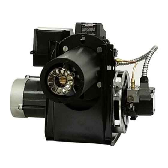
SPECIFICATIONS
MODEL
EH, EHA &
EHASR
OIL BURNERS
Fuels:
Use No.1 or No.2 heating oil (ASTM D-396),
Kerosene, Diesel (ASTM D975-18), JP8
Dimensions (
Standard
Height ......................................12 1/2"
Width .......................................15 1/2"
Depth ....................................... 8 1/4"
Center Line of Tube to Floor ......... 8 1/16"
Mounting:
Rigid Flange, Adjustable Flange, or Pedestal
Mount
1
UL File Number: MP-98
):
Advertisement
Table of Contents

Related Manuals for Wayne EH


Summary of Contents for Wayne EH
- Page 1 MODEL WAYNE COMBUSTION SYSTEMS 801 GLASGOW AVE. FORT WAYNE, IN 46803 EH, EHA & PHONE: (260) 425-9200 EHASR (855) WAYNECS (800) 443-4625 FAX: (260) 424-0904 OIL BURNERS www.waynecombustion.com Manual 21530 | Revision 10 | Publication Date: 9/14/18 UL File Number: MP-98...
- Page 2 INSTALLATION LOG BURNER MODEL: SPECIFICATION NUMBER: FUEL: Nozzle Size and Pattern: Pump Fuel Pressure (psi): (%): Smoke Spot: CO (PPM): INSTALLER’S NAME: CONTRACTOR NAME: CONTRACTOR CONTRACTOR PHONE ADDRESS: NUMBER: CONTRACTOR LICENSE #: DATE OF INSTALLATION: COMMENTS ABOUT INSTALLATION/START UP: BURNER/APPLIANCE SERVICE LOG SERVICE COMPANY CONTRACTOR...
- Page 3 Overview of Safety Warning System and Your Responsibilities The safety of you and others depends upon you thoroughly reading and understanding this manual. If you have questions or do not understand the information presented in this manual, please call Wayne Combustion Systems or see www.waynecombustion.com.
- Page 4 State of California to cause cancer or birth defects or other reproductive harm. For more information, go to www.p65Warnings.ca.gov. Special When contacting Wayne Combustion Systems for Requirements service information, please have the burner specification and model number when calling or writing.
-
Page 5: Table Of Contents
Contents GENERAL INFORMATION ..........................6 TROUBLESHOOTING............................7 GENERAL TROUBLESHOOTING GUIDE ..................... 7 BURNER DOES NOT LIGHT, HONEYWELL CONTROL REMAINS ON STANDBY ........10 BURNER WILL LIGHT, BUT WILL NOT STAY LIT DURING “CALL FOR HEAT” ........11 WIRING DIAGRAMS ............................16 SEQUENCE OF OPERATION: BURNERS WITH R7284G AND R8184G CONTROLS ........ -
Page 6: General Information
An EHA burner is different from a EH because the EHA uses an oil pump that is rated up to 3 gal/hr, while the EH model will use a larger pump that is rated up to 7 gal/hr to attain the higher firing rates. -
Page 7: Troubleshooting
The Honeywell R7284 oil primary control’s reset button is the “i” button, the R7184, R8184 and Wayne control is the big red button. Pressing the reset button and restarting the burner more than once with the burner not lighting could cause oil buildup in the firing chamber. This will... - Page 8 (push and hold for 3 seconds if it is an older style safety check and remains in standby Wayne control), observe burner sequence of operations. If mode (Applicable only if burner comes burner remains on standby see Burner does not light, with oil primary control).
- Page 9 PROBLEM POSSIBLE CAUSE SOLUTION BURNER SMOKES Heavy accumulation of soot on heat Remove burner assembly from heat exchanger. Clean (continued) exchanger and burner assembly thoroughly. Faulty burner nozzle spray pattern Replace. See page 22 for instructions. Misaligned or damaged electrode Realign electrodes according to Figure 14 or Figure 15 on pages 26-27, and the oil gun depth according to Figure 16 or Figure 17 on pages 27-28.
-
Page 10: Burner Does Not Light, Honeywell Control Remains On Standby
Troubleshooting tables on pages 10-11 are specific to burners that come equipped with an oil primary control, and these sections only apply if the general troubleshooting guide tells the licensed contractor to consult these sections while servicing the burner. NOTE: This section refers to Honeywell R7284 and R8184 series controls. The R7284G and R8184G control use a LED light to display the troubleshooting status, and the R7284P control comes with a display screen that will output the current operating state of the burner or any troubleshooting errors that might arise in normal burner operation. -
Page 11: Burner Will Light, But Will Not Stay Lit During "Call For Heat
BURNER WILL LIGHT, BUT WILL NOT STAY LIT DURING “CALL FOR HEAT” Procedure Status Corrective Actions Check limit switches --------------------- --------------------- Check for line voltage at the oil primary control --------------------- --------------------- (120 volts) R7284 or R8184 control is in lockout. - Page 12 Check cad cell sighting for view of flame. Disconnect line Burner locks out. Go to step 9 voltage power and open line switch. Unplug cad cell and clean face with soft cloth. Check sighting for view of flame. Place cad cell back in socket.
- Page 13 Figure 1- Burner Components – Models EHASR, EHA, and EH...
- Page 14 Table 1- EHASR, EHA, and EH Replacement Parts Description EHASR Description EHASR Motor - 1/5 HP, Pump – A2VA- 24003-001 24003-001 101128-009 120V PSC 3006/120V SOL. 120V Solenoid Motor – 1/5 HP, 21569 21569...
- Page 15 Figure 2– Oil Gun Assembly Detail View (Parts not necessarily as shown) Table 2- Oil Gun Replacement Parts Part Description EHASR Nozzle Adaptor 12988-002 12988-002 21913-SER Stamped Stabilizer Support Kit 21923-001 21923-001 21923-001 Cast Stabilizer Support Kit 21408-SER 21408-SER 21408-SER Stem/Insulator Kit 13286 13286...
-
Page 16: Wiring Diagrams
WIRING DIAGRAMS REMOVE JUMPER TO USE THERMOSTAT TERMINALS Figure 3- Wiring Diagram for 120V Honeywell R7284G & 230V Honeywell R8184G Controls REMOVE JUMPER TO USE THERMOSTAT TERMINALS Figure 4- Wiring Diagram for 120V Honeywell R7284P Control... -
Page 17: Sequence Of Operation: Burners With R7284G And R8184G Controls
Figure 5- Wiring Diagram for 120/230V Burners without a control SEQUENCE OF OPERATION: BURNERS WITH R7284G AND R8184G CONTROLS BURNER OPERATION On every call for heat the oil primary control performs an internal safety check which takes five seconds to complete. During these five seconds, the oil primary control verifies that the cad cell is outputting a “no flame”... -
Page 18: Sequence Of Operation: Burner With R7284P Control
Intermittent flame failure occurs during a “call for heat” If the oil primary control stops sensing a flame after the flame has been proven and the trial for ignition timer has expired, the oil primary control enters a limited recycle mode where it will de-energize the burner for one minute, while the LED light will flash for 2 seconds on, and 2 seconds off. -
Page 19: Sequence Of Operation: Burner Without Control
Make sure system is electrically energized, check circuit breaker, fuses, and close system switch if provided. Press and hold the oil primary control i button for two seconds and release (big red button for three seconds for old Wayne control). Set thermostat (controller) to “call for heat”. ... -
Page 20: General Installation Information
FUEL PUMPS Model EHASR, EHA and EH oil burners are provided with single stage 3450 RPM fuel pumps with the by-pass plug removed for a single pipe installation. This is satisfactory where the fuel supply is on the same level, or above burner, permitting gravity flow of oil. -
Page 21: Fuel Tanks
FUEL TANKS Local codes and regulations must be followed regarding tank and burner installation. Check existing tanks for water and sludge accumulation; clean if necessary. Also clean or replace existing piping. ELECTRICAL WIRING OF BURNER The oil burner is shipped completely wired. It is only necessary to supply the line voltage circuit, thermostat and limit circuit. -
Page 22: Air Supply For Combustion
In order to install or change the nozzle, the oil gun assembly needs to be removed from the burner. The EHASR, EHA, and EH burners has an arrow decal that lines up with the leading edge of the oil gun slot cover plate. This will help with re- installing the oil gun in the proper position once the nozzle has been installed. - Page 23 Figure 7 EH/EHASR Oil Line Assembly Fitting 2. Loosen and disconnect the brass nut of the copper oil line assembly from the oil gun assembly fitting and rotate the oil line out of the way (Figure 8). Figure 8 EH/EHASR Oil Line Removal...
- Page 24 Hold down clip Hold down clip Motor Flange Figure 9 EH/EHASR Ignitor mounting plate screw removal 4. Using a 9/16 inch wrench loosen and remove the oil gun assembly locknut (Figure 10). Figure 10 EH/EHASR Oil Gun Lock Nut Removal...
- Page 25 Figure 11 EH/EHASR Oil Gun Removal 6. While rotating the oil line fitting adapter up at a 45 degree angle, gently lift, but do not force, the entire gun assembly out of the housing opening (Figure 12). Figure 12 EH/EHASR Oil Gun Removal (Continued)
- Page 26 Stamp Figure 13 EH/EHASR Oil Gun Nozzle Installation (Flamelock and electrodes removed for clarity). 8. Identify which burner model you have, then measure and verify that the electrode spacing is per Figure 14 or Figure 15 on page 27, if not correct to factory settings.
-
Page 27: Setting Gun Depth
28. (For EHA and EH Burners Only) Suggested startup setting: EHA Flamelock flush with cast iron cone face. EH Flamelock 1/8” ahead of cast iron cone face for 3.00 to 4.50 gal/hr or ¼” ahead for 5.00 to 6.00 gal/hr... - Page 28 Figure 17– EHASR Gun Depth Settings 1. Identify which E burner model you have and set the gun depth accordingly. 2. To position the gun assembly forward or backwards, loosen the gun assembly 3/8-24 hex lock nut with a 9/16 inch wrench and the 5/16 inch hex slotted slot cover screw as shown in Figure 18.
- Page 29 BURNER INSTALLATION The EHASR, EHA, and EH oil burners were designed for furnaces, boilers, water heaters and a wide variety of commercial applications ranging from pressure washers & asphalt trucks The burner is supplied as a completely assembled unit. This burner should be installed into your appliance with the appliance manufacturer’s recommendations;...
-
Page 30: Starting Procedure
Figure 20– Combustion Chamber Installation Recommendations Note: The air tube length (DIM. A) is the distance from the front of the air tube retainer flange to the air tube cutoff where the air cone mounts in the tube. Note adjustable flange width. STARTING PROCEDURE STARTING BURNER Be sure that the electrical breaker to the appliance is in the “OFF”... - Page 31 Open the ignition device mounting plate and turn on the electrical breaker. Next, bleed the pump by following steps 1-3 before starting the burner. See Figure 22 for the location of the bleeder valve on the pump. Bleeder Valve Figure 22– Fuel Pump Bleeder Valve Location Note: If the pump is set up in two pipe operation with the by-pass plug installed, bleeding the pump is not necessary.
-
Page 32: Final Adjustments
2. With the burner running, use a 3/8 inch wrench to open the bleeder valve about one-half turn (Figure 24). Allow oil to drain into the container until a steady, clear bubble free oil stream is noticed. Close the bleeder plug. Figure 24–... -
Page 33: Final Checks
FINAL CHECKS Be sure all screws are locked and the controls on heating unit are adjusted in accordance with the heater and control manufacturer’s instruction sheets. Note: O % should be over 3 %, and for CO emissions the lower the better but, typical applications for pressure washers should be under 250 ppm, and under 125 ppm for boilers. -
Page 34: Reference Information
REFERENCE INFORMATION Table 3- Efficiency Chart for No. 2 Fuel Oil Net Stack Temperature (°F) 300° 350° 400° 450° 500° 550° 600° 650° 700° 750° 800° 850° 900° 87.5 86.5 85.3 84.3 83.3 82.0 81.0 79.8 78.8 77.5 76.3 75.5 74.3 14.5 87.5... - Page 35 Table 4– Max Suggested Firing rate for a Given Combustion Chamber Size Firing Diameter Rect. Nozzle Rectangular Rate Square Chamber Round Chamber Distance Chamber (gal/hr) Chamber Height to Floor 0.75 10" 8" x 9" 9" 4" 1.00 11" 10" x 10" 10"...
-
Page 36: Reference Figures
REFERENCE FIGURES Figure 25- Pump Feature Identification Figure 26– Blower Wheel Spacing... -
Page 37: Oil Pipe Sizing Information
OIL PIPE SIZING INFORMATION L= Max total line length (ft.), H+R H= Vertical distance in feet from bottom of tank to centerline of pump, or lift (ft.) R= Horizontal distance in feet from tank to centerline of burner pump (ft.) Q=firing rate capacity of fuel pump (gal/hr) Figure 27–... - Page 38 One Pipe Operation NOTE: For one-pipe operation (no return line) use the following line length equations 3/8” line: L=(6-.75H)/.0086Q 1/2” line: L=(6-.75H)/.00238Q NOTE: If tank is above the pump, change the “-“ to a “+” Sample Calculation for one pipe operation If the fuel tank is installed below the ground and it is found that the distance from the bottom of the tank to the centerline of fuel pump is H=7 ft, ½...
-
Page 39: Warranty
LIMITED WARRANTY by apply to you. WAYNE neither assumes or authorizes WAYNE shall be repaired or replaced at WAYNE’s any person to assume for WAYNE any other liability or sole option. obligation in connection with the sale of these products. - Page 40 NOTES...
Need help?
Do you have a question about the EH and is the answer not in the manual?
Questions and answers