Table of Contents
Advertisement
Quick Links
Download this manual
See also:
Manual
WAYNE COMBUSTION SYSTEMS
www.waynecombustion.com
Burner Model:
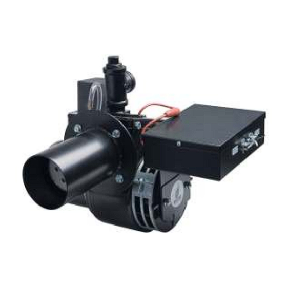
EHG
Minimum Input:
425 MBtu/hr (125 kW)
Maximum Input:
700 MBtu/hr (205 kW)
Standard Voltage:
120 VAC / 60 Hz 1 Phase
Flame Safety:
24 VAC Single-Rod Gas Primary
Supply Line Pressure Required: Natural or Propane 6" w.c. (1494 pa) Minimum,14"
w.c. (3487 Pa) Maximum
Ignition: 15.6k VAC Direct Spark Ignition. Standard burners are shipped with the ignition transformer mounted to the burner. If the
transformer is to be remotely mounted, the ignition wire must not exceed 36" (914.4mm) per UL795.
De-rate maximum input for altitude over 2000 ft. (610 m) by 4% each 1000 ft. (305 m) above sea level.
INSTALLATION OF THE BURNER MUST BE DONE BY A QUALIFIED INSTALLER IN ACCORDANCE WITH REGULATIONS OF
THE NATIONAL FUEL GAS CODE ANSI Z223.1/NFPA 54, AND IN COMPLETE ACCORDANCE WITH ALL LOCAL CODES AND
AUTHORITIES HAVING JURISDICTION.
INCORRECT INSTALLATION, ADJUSTMENT, OR MISUSE OF THIS BURNER WILL VOID THE WARRANTY and COULD
RESULT IN DEATH, SEVERE PERSONAL INJURY, OR SUBSTANTIAL PROPERTY DAMAGE.
A QUALIFIED INSTALLER IS THE PERSON WHO IS RESPONSIBLE FOR THE INSTALLATION AND ADJUSTMENT OF THE
EQUIPMENT AND WHO IS LICENSED TO INSTALL GAS-BURNING EQUIPMENT IN ACCORDANCE WITH ALL CODES AND
ORDINANCES.
THESE INSTRUCTIONS SHOULD BE AFFIXED TO THE BURNER
801 GLASGOW AVE.
FORT WAYNE, IN 46803
PHONE: (260) 425-9200
(855) WAYNECS
(800) 443-4625
FAX: (260) 424-0904
Manual 63537-001 | Revision K | Publication Date: 6/9/2014
SPECIFICATIONS
INSTALLATION OF BURNER
OR ADJACENT TO THE HEATING APPLIANCE.
EHG
Gas Burner
Mounting Flange:
Adjustable Flange Standard
Air Tube Diameter:
4 inches (101.6 mm)
Air Tube Insertions:
5 inches (127 mm) Maximum with 6 inch
(152 mm) Air Tube.
7 inches (178 mm) Maximum with 9 inch
(228 mm) Air Tube.
10 inches (254 mm) Maximum with 12 inch
(305 mm) Air Tube.
13 inches (381 mm) Maximum with 15 inch
(381 mm) Air Tube.
1
Advertisement
Table of Contents

Related Manuals for Wayne EHG


Summary of Contents for Wayne EHG
-
Page 1: Specifications
WAYNE COMBUSTION SYSTEMS 801 GLASGOW AVE. FORT WAYNE, IN 46803 PHONE: (260) 425-9200 (855) WAYNECS (800) 443-4625 Gas Burner FAX: (260) 424-0904 www.waynecombustion.com Manual 63537-001 | Revision K | Publication Date: 6/9/2014 SPECIFICATIONS Mounting Flange: Adjustable Flange Standard Burner Model:... - Page 2 INSTALLATION LOG BURNER MODEL: SPECIFICATION NUMBER: FUEL (NATURAL OR GAS ORIFICE DRILLED PROPANE): SIZE: INLET GAS PRESSURE (%): (%): CO (PPM): (in. w.c.): INSTALLER’S NAME: CONTRACTOR NAME: CONTRACTOR CONTRACTOR PHONE ADDRESS: NUMBER: CONTRACTOR LICENSE #: DATE OF INSTALLATION: COMMENTS ABOUT INSTALLATION/START UP: BURNER/APPLIANCE SERVICE LOG SERVICE TECHNICIAN...
- Page 3 If the information in these instructions is not followed exactly, a fire or explosion may result causing property damage, personal injury or death. FOR YOUR SAFTEY: FOR YOUR SAFTEY: FOR YOUR SAFTEY: FOR YOUR SAFTEY: DO NOT STORE OR USE GASOLINE OR OTHER FLAMMABLE VAPORS AND LIQUIDS IN THE VINCINITY OF THIS OR ANY OTHER APPLIANCE.
-
Page 4: Table Of Contents
CONTENTS PAGE SECTION I INSTALLATION A. GENERAL B. VENTILATION C. MOUNTING TO EQUIPMENT D. GAS PIPING E. ELECTRICAL SUPPLY F. BURNER ORIFICE SIZING AND INSTALLATION G. 120VAC SOLENOID SHUT-OFF GAS VALVE H. PRESSURE REGULATOR ADJUSTMENT GAS PRESSURE SWITCHES SECTION II INITIAL START UP SECTION III OPERATION AND TROUBLESHOOTING SECTION IV SERVICE TECHNICAL INFORMATION... -
Page 5: Section I Installation
A drip leg or sediment trap must be installed in the supply line to the burner. A pipe union shall be The EHG burner models covered by this manual shall installed in the gas line adjacent to, and upstream not be installed in an appliance located where normal from the main gas manual shutoff valve. - Page 6 ELECTRODE SETTINGS PROBE DIM “A” REF IGNITER 1.06 (26.9mm) 0.8” (20.3mm) REF SENSOR 0.84 (21.3mm) 0.75” (19.1mm) 0.105” (2.7mm) 0.125” (3.2mm) Figure 1 Manual Shutoff Valve 1/8” (3.2mm) N.P.T. Plugged Tapping Pressure Gage Port Direction of Flow Union Control Manifold 3’’...
-
Page 7: Electrical Supply
In Canada, all wiring shall be done in The EHG burner models are shipped labeled and accordance with the Canadian Electrical Code. orificed for natural gas. To convert to propane gas... - Page 8 Gas Pipetrain: The pipetrain includes High & Low Gas Pressure Safety Switches, two manual ball valves, two 120 VAC Solenoid Shut-off Valves, a Main Gas Pressure Regulator, and gas test ports per the requirements of UL795. Upon request the pipetrain can be supplied without a Gas Pressure Regulator, but the correct Gas Pressure Regulator must be installed before operation.
- Page 9 There are two sets of wires extending out of the control panel. The black and white wires marked “L1” and “L2” should be connected to the 120 VAC supply line. The black and white wires marked “GV1” and “GV2” are to be connected to the gas train.
-
Page 10: 120Vac Solenoid Shut-Off Gas Valve
G. 120VAC SOLENOID SHUT-OFF GAS VALVES The gas solenoid shut-off valves may be pre-plumbed onto the pipetrain. The pipetrain may also be pre-wired for convenience, but the electrical wiring from the burner must be connected in the field. Figure 5 Figure 6 Figures 5 and 6 show one type of solenoid valve that is used in the gas trains. -
Page 11: Gas Pressure Switches
The 1/8″ NPT pressure tap for manifold pressure measurement is located on the side of the burner’s manifold pipe (see figure 4). Use a “u”-tube manometer or dial type pressure gauge, scaled from 0″w.c. to 15.0″ w.c. (3736.5Pa) to read pressure. -
Page 12: Section Ii Initial Start Up
NOTE: Remove block-out plate using a 1/2" nut driver or wrench from the side of the burner IF the firing rate is over 650,000(191 kW) Btu/hr on LP ONLY. See chart below. For location of block-out plate see figure 9 below. EHG Start-Up Reference Chart LP Gas... - Page 13 NOTE: Initial activation of the burner should begin with checking the function of the automatic controls by means of a “dry run” before gas is supplied to the main burner nozzle – through a complete main burner firing cycle and a complete check of all automatic safety controls with the test firing valve in the closed position then through an activated firing cycle.
- Page 14 AIRFREE % CO C. NOTE: The EHG was designed to fire into slightly positive, balanced, or slightly negative combustion chambers. For optimal performance, check overfire draft and adjust to NEGATIVE -.01 (-2.5Pa) to -.02 (-5.0 Pa) inches w.c. during burner operation.
-
Page 15: Section Iii Operation And Troubleshooting
SECTION III OPERATION AND TROUBLESHOOTING SEQUENCE OF OPERATION – EHG POWER GAS BURNER UTILIZING HONEYWELL S89F GAS PRIMARY W/BUILT IN 30 SECOND PREPURGE On a call for heat, voltage (24VAC) is applied to the motor start relay and air switch. Once the fan motor reaches operating rpm, the available combustion air will close the air-proving switch contacts, energizing the gas primary control. - Page 16 EHG POWER GAS BURNER WITH HONEYWELL S89F GAS PRIMARY AND GAS TRAIN ASSEMBLY Figure 11...
- Page 17 EHG POWER GAS BURNER WITH HONEYWELL S89F GAS PRIMARY AND GAS TRAIN ASSEMBLY (CONTINUED) Figure 11 (continued)
- Page 18 FLAME SENSING The Honeywell S89 series primary ignition controls utilize the flame current rectification principal for main burner flame sensing. The flame rectification phenomenon occurs as follows: The ignited gas flame causes the immediate atmosphere around the flame to become ionized (gas atoms become electrically charged). The ionization causes the atmosphere around the flame to become electrically conductive.
- Page 19 EHG SERIES WITH A HONEYWELL S89F PRIMARY IGNITION CONTROL TROUBLESHOOTING GUIDE MOTOR DOES NOT START DIAGNOSE REASON FOR ABSENSE OF 1. CHECK VOLTAGE INPUT TO BURNER, 120 VAC VOLTAGE 2. CHECK FOR VOLTAGE AFTER BURNER “ON” SWITCH REPLACE SWITCH 3. CHECK FOR CONTINUITY THROUGH 24 VOLT T-STAT IF USED, OR IF BURNER...
- Page 20 IGNITION ARC ESTABLISHED – NO FLAME 1. RESET CONTROL-MOTOR STARTS-COMPLETES 30 SECOND PREPURGE CYCLE, 8 SECOND SAFE START CHECK AND TRIAL FOR IGNITION, 4 SECONDS HONEYWELL SERIES S89F. NOTE:THE BURNER MOTOR WILL CONTINUE TO OPERATE DURING THE LOCK OUT MODE WHEN THE THERMOSTAT CIRCUIT IS CALLING FOR BURNER OPERATION. 2.
- Page 21 GAS TRAIN TROUBLESHOOTING CHECK TO MAKE SURE 120 VOTLS IS PRESENT ACROSS THE WIRES FEEDING THE GAS TRAIN DURING IGNITION TRIALS. IF NOT, RETURN TO STEP 4 UDNER “IGNITON ARC ESTABLISHED - NO FLAME”. 1. ADJUST HIGH AND LOW GAS PRESSURE SWITCHES AS OUTLINED IF BURNER FIRES, ADJUST HIGH AND LOW GAS PRESSURE IN SECTION II.14 IF THERE IS NO GAS FLOW CONTINUE BELOW.
- Page 22 NO IGNITION ARC ESTABLISHED 1. RESET CONTROL: -MOTOR STARTS – COMPLETES 30 SECOND PREPURGE CYCLE, 8 SECOND SAFE START CHECK SERIES. -GAS VALVE OPENS, REGULATING ADEQUATE GAS PRESSURE. -NO FLAME ESTABLISHED – PRIMARY CONTROL LOCKS OUT AFTER 4 SECOND HONEYWELL SERIES TRIAL FOR IGNIITION PERIODS. IN ORDER FOR THE FOLLOWING FUNCTIONAL TEST TO BE MADE, THE CONTROL MUST BE RESET AND THE TESTS MONITORED DURING THE 4 SECOND HONEYWELL SERIES TRIAL FOR IGNITION THAT OCCURS AT THE END OF THE 30 SECOND PREPURGE CYCLE, AND THE 8 SECOND SAFE START CHECK.
- Page 23 NO IGNITION - NO GAS FLOW 1. RESET CONTROL – MOTOR STARTS – AFTER 30 SECOND PREPURGE CYCLE AND 8 SECOND SAFE START CHECK. MOTOR CONTINUES TO RUN BUT FLAME IS NOT ESTABLISHED IN ORDER FOR THE FOLLOWING FUNCTIONAL TEST TO BE MADE, THE CONTROL MUST BE RESET AND THE TESTS MONITORED DURING THE 4 SECOND HONEYWELL SERIES TRIAL FOR IGNITION THAT OCCURS AT THE END OF THE 30 SECOND PREPURGE CYCLE, AND THE 8 SECOND SAFE START CHECK.
- Page 24 LOSES FLAME DURING CYCLE – CONTROL LOCKS OUT ON SAFETY 1. RESET CONTROL: -COMPLETES 30 SECOND PREPURGE CYCLE, AND 8 SECOND SAFE START CHECK. -FLAME IS ESTABLISHED. -SOMETIMES THE CONTROL LOCKS OUT BEFORE THE THERMOSTAT OR CONTROLLING CIRCUIT IS SATISFIED. PROBABLE CAUSE OF ERRATIC LOCKOUT: 2.
- Page 25 BURNER CYCLES ERRATICALLY Check for proper thermostat installation, location, and performance. If thermostat is used, remove wires at T-T terminals and replace with jumper wire. If burner runs properly, check thermostat for proper operation. 2. Check low voltage circuit for bad wiring, electrical connections and/or switches.
-
Page 26: Section Iv Service
SECTION IV SERVICE Caution: Make sure the manual gas valves and main electrical power to the burner are turned off before opening burner or removing any parts for service. A. BURNER HEAD AND ELECTRODE/SENSOR ASSEMBLY The burner head, electrode, sensor probe, orifice housing and housing cover are part of the burner head assembly which can be removed as one unit (Figure 16). - Page 27 3. To begin removing gas train assembly, gently lift up rear of housing cover while pulling back. Rotate the assembly about 90 degrees toward the left side of the burner and gently extract burner head and electrode/sensor assembly out of opening in housing taking extreme care to not dislocate or damage electrode or sensor probe (Figure 15). Figure 15 Figure 16 4.
- Page 28 WARNING: For proper air switch operation, the burner must be mounted in the horizontal position. If it is necessary to mount the burner in a vertical position, the air switch must be repositioned to the horizontal. Contact Wayne Combustion Systems for details.
- Page 29 C. COMBUSTION AIR BLOWER AND MOTOR 1. Cleaning of the combustion air blower is indicated if the blades show an accumulation of dust and lint, or if the character of the flame indicates a deficiency of combustion air. 2. The motor and blower wheel are removed as one assembly. With the burner head and electrode/sensor assembly (Figure 13) out of the burner, disconnect the motor wires (Figure 18).
- Page 30 Motor Blower Wheel Figure 20 CAUTION: Do not remove blower wheel from motor shaft during periodic cleaning. Should removal of the blower wheel be necessary for cleaning or replacement of it or the motor, the blower wheel must be positioned correctly on the motor shaft (Figure 21). 0.09”...
- Page 31 E. AIR BAND ASSEMBLY ADJUSTMENT 1. The air band assembly is located on the left side of the burner housing, opposite the motor. The air bands are held in place by a 1/2” bolt. Air Band Assembly Figure 22 2. Using a 1/2” nut driver, loosen the bolt holding the air bands in place. Figure 23 CAUTION: Do not remove the bolt or the air bands.
- Page 32 3. The air band assembly can now be adjusted from the fully closed position (figure 24), to the fully open positions (figure 25) by sliding the outer ring. Fully Closed Position Figure 24 Fully Open Position Figure 25...
- Page 33 4. To measure the air band opening, place a ruler or other measuring device alongside the air band and measure the opening from the lip of the solid black piece inside the air band assembly to the edge of the air band itself. Measurable Opening Lip inside...
-
Page 34: Technical Information
TECHNICAL INFORMATION “Troubleshooting Guide” Nuisance Lockouts/Flame Sensing Problems – EHG Gas Burners Wayne’s EHG series direct spark ignition (DSI) gas The flamerod probe should be free of soot and • burners prove flame through the process of flame creosote. Deposits may insulate the probe, leading it rectification. - Page 35 Cover / Manifold / Orifice Assembly Figure 27...
- Page 36 Burner Exploded and Assembled Views 64021-003 Figure 28...
- Page 37 21724-011 FALNGE ASM., ADJ-BLACK W/ GASKET 63529-001 COVER, FAN INLET-BLACK 62388-XXX TIMER, 30 OR 60 SEC 24 VAC 63479-004 CONTROL BOX ASM-EHG NO IGN 13073-002 COVER, J-BOX-EHG-CSD1 63873-001 IGNITOR, A 2260-TW 120V 50/60 SEE FIG 27 MANIFOLD / CVR ASM-EHG...
- Page 38 Control Box Assembly 63479-004 or 63479-005 Figure 29...
- Page 39 Control Box Assembly 63479-004 or 63479-005 Figure 29 (Continued)
- Page 40 Model* DIM. “A” DIM. “B” 15.3 14.7 17.3 16.7 20.3 19.7 23.3 22.7 *Denotes Air Tube Length Burner Dimensions Figure 30...
- Page 41 Gas Train Assembly with Regulator 63527-001 Figure 31...
- Page 42 Gas Train Assembly with Regulator 63527-001 Figure 31 (Continued) Parts List Item Part No. Description 63503-001 Valve, Manual Ball 1” 63504-001 Valve, Gas Shutoff 1” 120V 63262-003 Regulator, Gas Pressure RV61 63513-002 Switch, Gas Pressure High (Antunes HPG-G) 63513-001 Switch, Gas Pressure Low (Antunes LPG-G)
- Page 43 Pipe Sizing Chart for Natural Gas The following chart is based on 0-0.5 psi inlet pressure, specific gravity of 0.6, and a pressure loss of 0.5” w.c.. Numbers are for straight schedule 40 metal pipe. Maximum Capacity in Cubic Feet of Gas per Hour Length of 3/4"...
-
Page 45: Consumer Instructions
CONSUMER INSTRUCTIONS Keep the area around the burner clear and free of combustible materials, gasoline or other flammable liquids or vapors. Do not obstruct burner air openings or ventilation grilles for combustion air. If the burner is to be shut down for an extended time, the main manual gas valve should be closed as a precaution. -
Page 46: Warranty
Also, some states do not allow the WAYNE is not responsible for any labor cost for the exclusion or limitation of incidental or consequential removal and replacement of said burner or burner damages, so the above limitation or exclusion may not components and equipment associated therewith. - Page 47 NOTES...
Need help?
Do you have a question about the EHG and is the answer not in the manual?
Questions and answers