Table of Contents
Advertisement
WAYNE COMBUSTION SYSTEMS
Note: Dimensions in parentheses ( ) are informational only. English values take priority.
BURNER MODELS MINIMUM INPUT
HSG200
HSG400
FUELS: Natural Gas and LP Gas
AVAILABLE VOLTAGES: 120 Vac 60 Hz, 230 Vac 50/60 Hz 1 Phase
AIR TUBE DIAMETER: 4 in (101.6 mm) MOUNTING: Adjustable Flange is standard; Pedestal Mount is Optional
READ THIS MANUAL BEFORE USING THIS PRODUCT. FAILURE TO FOLLOW THE
INSTRUCTIONS AND SAFETY PRECAUTIONS IN THIS MANUAL CAN RESULT IN
SERIOUS INJURY OR DEATH. KEEP THIS MANUAL FOR FUTURE REFERENCE.
INSTALLTION OF THE BURNER MUST BE DONE BY A QUALIFIED INSTALLER IN
ACCORDANCE WITH REGULATIONS OF THE NATIONAL FUEL GAS CODE ANSI
Z223.1/NFPA54, AND IN COMPLETE ACCORDANCE WITH ALL LOCAL CODES AND
AUTHORITIES HAVING JURISDICTION.
A QUALIFIED INSTALLER IS THE PERSON WHO IS RESPONSIBLE FOR THE
INSTALLATION AND ADJUSTMENT OF THE EQUIPMENT AND WHO IS LICENSED
TO INSTALL GAS-BURNING EQUIPMENT IN ACCORDANCE WITH ALL CODES AND
ORDINANCES.
801 GLASGOW AVE.
FORT WAYNE, IN 46803
PHONE: (260) 425-9200
(855) WAYNECS
(800) 443-4625
FAX: (260) 424-0904
www.waynecombustion.com
Manual 62484 | Revision D | Publication Date: 4/25/2018
SPECIFICATIONS
60,000 Btu/hr (18 kW)
200,000 Btu/hr (59 kW)
FLAME SAFETY: 24 Vac Electronic
MAXIMUM INPUT
200,000 Btu/hr (59 kW)
400,000 Btu/hr (117 kW)
HSG200
HSG400
Gas Burners
CSA CERTIFICATION:
189810-1154925
ANSI Z21.17
MASS G3-0903-67
Air Tube Standard Lengths
6, 9,12 in. (153, 229, 305 mm)
6, 9,12 in. (159, 229, 305 mm)
IGNITION: 7300 Vac Direct Spark
Advertisement
Table of Contents
Troubleshooting

Subscribe to Our Youtube Channel
Related Manuals for Wayne HSG200


Summary of Contents for Wayne HSG200
-
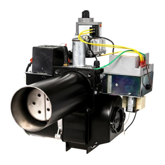
Page 1: Gas Burners
HSG200 WAYNE COMBUSTION SYSTEMS 801 GLASGOW AVE. FORT WAYNE, IN 46803 HSG400 PHONE: (260) 425-9200 (855) WAYNECS (800) 443-4625 Gas Burners FAX: (260) 424-0904 www.waynecombustion.com Manual 62484 | Revision D | Publication Date: 4/25/2018 Note: Dimensions in parentheses ( ) are informational only. English values take priority. - Page 2 Overview of Safety Warning System and Your Responsibilities The safety of you and others depends upon you thoroughly reading and understanding this manual. If you have questions or do not understand the information presented in this manual, please call Wayne Combustion System or see www.waynecombustion.com.
- Page 3 Hazard Level Pictogram Type Hazard Explanation Fire or Failure to follow safety warnings exactly could result in serious injury, death or property damage. Explosion Do not store or use gasoline or other flammable vapors and liquids in the vicinity of this or any other appliance.
- Page 4 “T” shape on the back of the burner and model number is at the top of the “T” shape on the back of the burner. If any instructions in the manual are not clear, contact Wayne Combustion Systems at 1-260-425-9200 for assistance.
- Page 5 INSTALLATION LOG BURNER MODEL: SPECIFICATION FUEL (NATURAL OR GAS ORIFICE SIZE: NUMBER: LP): INLET GAS (%): (%): CO (PPM): PRESSURE (in. w.c.): INSTALLER’S NAME: CONTRACTOR NAME: CONTRACTOR CONTRACTOR PHONE ADDRESS: NUMBER: CONTRACTOR DATE OF INSTALLATION: LICENSE #: COMMENTS ABOUT INSTALLATION/START UP: BURNER/APPLIANCE SERVICE LOG COMPANY CONTRACTOR...
-
Page 6: Table Of Contents
GENERAL INSTRUCTIONS FOR SERVICING BURNER .................. 26 SECTION V: SERVICE AND TROUBLESHOOTING ..................27 HSG SERIES BURNER UTILIZING WAYNE 64420 SERIES IGNITION CONTROLS .......... 27 HSG SERIES BURNER UTILIZING HONEYWELL IGNITION CONTROLS ............28 FLAME SENSING ON HSG SERIES BURNERS ....................29 TROUBLESHOOTING GUIDE PRIMARY IGNITION CONTROLS .............. -
Page 7: Section I: Installation And Setup
SECTION I: INSTALLATION AND SETUP These instructions were prepared for the guidance of those installing this particular gas conversion burner. While they apply in principle to all installations, they should not be interpreted as meaning the only safe and economical way to install a conversion burner. It may be necessary to deviate from these instructions in some instances in order to comply with local gas company rules or codes in effect in the area in which the installation is made. -
Page 8: Inspection Of Flue Pipe And Chimney
NOTE ON FIGURE 2: Ducts used for make-up air may be connected to the cold air return of the heating system only if they connect directly to outdoor air. Attic Ventilation Louvers are required at each end of attic with alternate air inlet No. -
Page 9: Inspection Of Heating Appliance
Where the chimney is unlined or where local experience indicates that flue gas condensate might be a problem, the local gas company should be consulted. The chimney should be examined and thoroughly cleaned, if necessary, before installation is made to make sure it will freely conduct the flue gases to the outside. - Page 10 Strict compliance to appropriate codes should be made regarding flue pipe clearances from combustible materials. A CSA type draft hood or its equivalent shall be placed in and made part of the flue pipe from the appliance. A barometric damper may be used in place of the draft hood where permitted by local building codes.
-
Page 11: Preparation Of Combustion Chamber
PREPARATION OF COMBUSTION CHAMBER Clean the combustion chamber thoroughly. Scrape and brush all heating surfaces and flue ways. Soot and fly ash are excellent insulators and unless removed, the efficiency of the heating appliance will be impaired. Plugged or restricted flue passages will prevent burner from operating properly. -
Page 12: Sizing Of Combustion Chamber
Figure 9 BURNER INSTALLATION The HSG200 and HSG400 power gas burners were designed for converting oil fired furnaces and boilers. Due consideration was given to making it as simple and easy to install and service as possible without weakening its durability or efficiency. -
Page 13: Determine Orifice Size And Rate
(Refer to orifice chart Figure 11). HSG200 is shipped from factory with a #8 - 0.199” orifice installed and HSG400 is shipped from the factory with a T - 0.358” orifice. The combination gas valve pressure regulator, which has an outlet pressure setting range of... - Page 14 HSG SERIES POWER GAS CONVERION BURNER ORIFICE CHART Manifold Pressure Orifice Size and Drill 2.0” (498 Pa) 3.0” (747 Pa) 4.0” (996 Pa) HSG200 Natural Gas #29 -.136 (3.5 mm) 50,000 (15) 64,000 (19) 76,500 (22) #8 - .199 (5.1mm)
-
Page 15: Changing The Orifice
CHANGING THE ORIFICE Before replacing the orifice, the gas supply and power must be shut off. The HSG200 is shipped from factory with a #8 - 0.199” orifice installed and HSG400 is shipped from the factory with a T - 0.358” orifice installed. - Page 16 ORIFICE GASKET Figure 13: HSG Cap with Gasket on Manifold Remove orifice spring to access and remove orifice (Figure 14). Orifice will be stamped with its size (Figure 15). Figure 14: HSG Cap with Gasket Removed and Spring Removed...
-
Page 17: Inspection And Sizing Of Gas Piping
Figure 15: HSG Orifice Install the new orifice in manifold, reinstall spring and cap with gasket in the manifold. The orifice kit included with conversion burners also contains gas identification labels. When changing from one gas to another, locate the gas identification label on the burner and if necessary, place the proper label from the kit over the label on the burner. - Page 18 Manual Shutoff Valve 1/8” (3.175mm) N.P.T. Plugged Tapping Pressure Gage Port Direction of Flow Union Control Manifold 3’’ MIN (76.2 mm) Pipe Cap Drip Leg Supply Line Connection to Burner Figure 16 The gas line should be a separate supply direct from the meter to the burner. It is recommended that new pipe be used and located so that a minimum amount of work will be required in future servicing.
- Page 19 Table 1: Pipe Sizing Chart for Natural Gas (0-0.5 psi) with Straight Schedule 40 Metal Pipe The following chart is based on 0-0.5 psi inlet pressure, specific gravity of 0.6, and a pressure loss of 0.5” w.c.. Maximum Capacity of Pipe Size in Btu/hr Length of 1/2”...
-
Page 20: Testing Piping For Leaks
Table 3: Pipe Sizing Chart for LP (11” w.c.) with Copper Tubing The following chart is based on 11” w.c. inlet pressure and a pressure drop of 0.5” w.c.. Maximum Capacity of Tube Size in Btu/hr Pipe Size 1/2” 5/8” 3/4”... -
Page 21: Inspection Of Limit Control Switches
Set the room thermostat “heat anticipator” for the total current draw of the 24 Vac burner operation circuit (HSG200 0.55 amps, HSG400 0.7 amps). Label all wires prior to disconnection when servicing controls. Wiring errors can cause improper and dangerous operation. Verify proper operation after servicing. -
Page 22: Section Ii: Initial Start Up
SECTION II: INITIAL START UP HSG200/400 Gas Valve HSG400 Gas Valve Honeywell VR8305 Robertshaw 7000 DERHC Figure 17: Gas Valves for HSG Series Burner HSG200/400 Gas Valve HSG400 Gas Valve Honeywell VR8305 Robertshaw 7000 DERHC... -
Page 23: Initial Burner Start Up Procedure
INITIAL BURNER START UP PROCEDURE READ THE APPLICATICABLE SEQUENCE OF BURNER/PRIMARY GAS CONTROL OPERATION IN SECTION V SERVICE AND TROUBLESHOOTING BEFORE PROCEEDING. 1. Depress the combination gas valve manual control knob and turn to “OFF” position. (For location of the manual control knob, refer to Figure 17). Remove the 1/8” NPT pressure tap plug from the gas valve and install a hose barb fitting. -
Page 24: Combustion Adjustment Of Burner
3. Turn on the main electrical power and set the thermostat or operation control to call for heat. Allow the burner to run a MINIMUM of 5 minutes to purge combustion chamber and appliance heat exchanger. 4. Set the thermostat or operating control below room temperature, shutting the burner “OFF” for 1 minute. -
Page 25: Section Iii: Gas Conversion
For the HSG200, if these values are not able to be achieved, the off cycle damper setting may need to be increased to adjust the burner. -
Page 26: Section Iv: Consumer Instructions
Orifice kits for the HSG200 and HSG400 burners are available from Wayne Combustion Systems. Some HSG burner models are sold to Original Equipment Manufacturers and are pre-set with the proper orifice for the firing rate and gas utilization for the specific equipment. -
Page 27: Section V: Service And Troubleshooting
After the 30 second pre-purge timing, the ignition control is energized. After the initial 30 second pre-purge provided by the external timer, the Wayne control is energized, and it will activate the gas valve allowing gas to flow to the burner head. Simultaneously, the ignition control energizes the ignition transformer, producing a spark at the electrode, establishing main burner flame. -
Page 28: Hsg Series Burner Utilizing Honeywell Ignition Controls
This Wayne ignition control has an internal 30 second pre-purge timer. After the initial 30 second pre- purge, the control simultaneously energizes the gas valve and ignition transformer. Gas flows to the burner head and the transformer produces a spark at the electrode establishing main burner flame. -
Page 29: Flame Sensing On Hsg Series Burners
restart the system, the main power or thermostat must be de-energized momentarily, then re-energized. If at any time during the heat cycle, there is insufficient supply of combustion air to the burner, the air switch contacts will open, putting the system into lockout closing gas valve. See Figure 27 for wiring diagram of HSG Series Burner utilizing the Honeywell S89E control. - Page 30 Figure 20: Flame Current Measurement, Top: Wayne control; Bottom: Honeywell control...
- Page 31 DIM “A” REF PROBE IGNITER 1 5/8 in (41.3mm) FLAME SENSOR 1 1/4 in (31.8mm) Figure 21: Igniter and Flame Sensor Probe Settings Figure 22: Burner Face and Flame Sensor Probe Location...
-
Page 32: Troubleshooting Guide Primary Ignition Controls
TROUBLESHOOTING GUIDE PRIMARY IGNITION CONTROLS MOTOR DOES NOT START Diagnose reason for Check voltage input to burner, 120 VAC. absence of voltage. Check continuity though 24 volt T-STAT if Repair T-STAT or add used, or if burner is cycled on-off through jumper as necessary. - Page 33 IGNITION ARC ESTABLISHED – NO FLAME Reset Control – Motor starts – Completes 30 second pre-purge cycle and 4 second trial for ignition. NOTE: the burner motor will continue to operate during the lockout mode when the thermostat circuit is called for burner operation. Check for correct orifice/air setting relationship (Figures 11, 18, 19).
- Page 34 NO IGNITION ARC ESTABLISHED 1. Reset Control Motor starts – Completes 30 second pre-purge cycle. Gas valve opens, regulating adequate gas pressure. No flame established – Primary control locks out after 4 second trial for ignition period. In order for the functional test described in Step 2 to be made, the control must reset and the voltage measured during the 4 second trial for ignition period that occurs at...
- Page 35 Reset Control – Motor starts- After 30 second pre-purge cycle, motor continues to run but flame is not established. If using a Wayne control, check the diagnostic LED for an error code. If a “LINE VOLTAGE ERROR,” is indicated check the connection between earth ground and the burner chassis.
- Page 36 Flame is established. Sometimes the control locks out before thermostat or controlling circuit is satisfied If using a Wayne control, check the diagnostic LED for an error code. Consult the table below to troubleshoot the issue. Probable causes of erratic lockout 1.
- Page 37 BURNER CYCLES ERRATICALLY Check for proper thermostat installation and location. If thermostat is used, remove wires at T-T terminals and replace with jumper wire. If burner runs properly, check thermostat for proper operation. Set the anticipator to the correct value Check thermostat heat anticipator for correct setting.
-
Page 38: Servicing Hsg Series Burner
SERVICING HSG SERIES BURNER (SERVICE TECHNICIAN ONLY) ELECTRICAL SHOCK HAZARD Make sure the main manual gas valve, manual control knob on the combination valve and electrical supply are turned off before opening burner or removing any parts for service. BURN HAZARD, HOT SURFACE Burner flange and air tube are hot when burner is in operation. - Page 39 3. Should removal of the blower wheel be necessary for cleaning or replacement of it or the motor, the blower wheel must be positioned correctly on the motor shaft (Figure 24). HSG200 blower wheel part number 21664 is positioned 2 1/16” (52.4mm) measured from the blower wheel inlet ring face to the side plate face.
-
Page 40: Troubleshooting Guide
Nuisance Lockouts/Flame Sensing Problems –HSG200 & HSG400 Gas Burners Wayne’s HSG series direct spark ignition (DSI) gas burners prove flame through the process of flame rectification. Flame rectification is achieved by the ignition control as it places a small voltage on the flame sensor. - Page 41 simply the failure of the system to sense the establishment of the flame. Should this situation exist for a period of time longer than the ignition control’s stated lockout timing, the control will shut down or go into permanent lockout. The only way to get the burner to recycle is to break, and then reinstate power to the burner.
-
Page 42: Hsg Wiring Diagrams
HSG WIRING DIAGRAMS HSG SERIES BURNER WITH WAYNE 64420-001 IGNITION CONTROL Figure 25: Wiring Diagram for Burners with Wayne 64420-001 Control... - Page 43 HSG SERIES BURNER WITH WAYNE 64420-002 IGNITION CONTROL Figure 26: Wiring Diagram for Burners with Wayne 64420-002 Control...
- Page 44 HSG SERIES BURNER WITH HONEYWELL S89E GAS PRIMARY CONTROL Figure 27: Wiring Diagram for Burners with Honeywell S89E Control...
- Page 45 HSG SERIES BURNER WITH HONEYWELL S89F GAS PRIMARY CONTROL Figure 28: Wiring Diagram for Burners with Honeywell S89F Control...
-
Page 46: Section Vi: Parts List And Exploded Views
Air Tube - HSG200 12" (304.8mm) 63270-027 Air Tube - HSG400 12" (304.8mm) 63270-028 Air Tube - HSG400 15" (381mm) 62393-SER Air Cone - (HSG200 only) (not shown) 21724-011 Adjustable Flange Assembly (includes gasket, not shown) 100428-002 Flange Gasket (not shown) 21664 Blower Wheel 5 1/4"... -
Page 47: Hsg Exploded Views
64095-001 Ignition Wire - 500mm Cable (230V 50/60Hz) Use with 64051-001 Ignition Transformer 8” Noise Suppression Ignition Wire, Use with Wayne controls; 6", 6 1/4" Burner 64460-001 14” Noise Suppression Ignition Wire, Use with Wayne control; 9", 12", 15" Burner... - Page 48 Figure 29 continued: Junction Box Assemblies Exploded Figure 30: Motor Assembly Exploded...
- Page 49 Figure 31: Gun Assembly Exploded Figure 32: HSG Series Burner Exploded...
- Page 50 13.2 (335 mm) REF. 7.7 in (195mm) 15.25 in (377 mm) 7 in (178 mm) Figure 33: Outer Dimensions of HSG Series Burner...
-
Page 51: Section Vii: Warranty
WAYNE is not responsible for any labor cost for the apply to you. WAYNE neither assumes or authorizes removal and replacement of said burner or burner any person to assume for WAYNE any other liability or components and equipment associated therewith. - Page 52 NOTES...
Need help?
Do you have a question about the HSG200 and is the answer not in the manual?
Questions and answers