Table of Contents
Advertisement
Quick Links
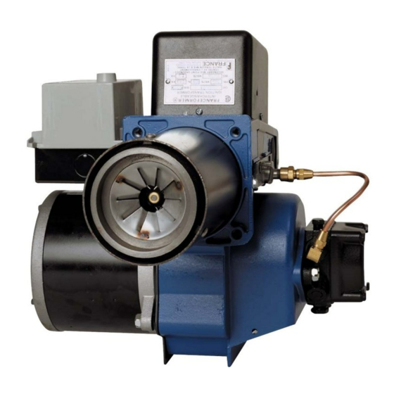
WAYNE COMBUSTION SYSTEMS
Firing Capacity:
70,000 – 420,000 BTU/HR
0.50 – 3.00 GPH
(additional hardware required to fire above 2.50 GPH)
Electrical:
Power Supply..............115V / 60Hz / 1-Phase
Motor...............................................3450 RPM
Ignition...................................10,000V / 23mA
INSTALLATION OF THE BURNER MUST BE DONE BY A QUALIFIED INSTALLER IN ACCORDANCE WITH REGULATIONS OF THE NATIONAL
FIRE PROTECTION STANDARD FOR OIL-BURNING EQUIPMENT, NFPA NO. 31, AND IN COMPLETE ACCORDANCE WITH ALL LOCAL CODES
AND AUTHORITIES HAVING JURISDICTION.
A QUALIFIED INSTALLER IS THE PERSON WHO IS RESPONSIBLE FOR THE INSTALLATION AND ADJUSTMENT OF THE EQUIPMENT AND
WHO IS LICENSED TO INSTALL OIL-BURNING EQUIPMENT IN ACCORDANCE WITH ALL CODES AND ORDINANCES.
THESE INSTRUCTIONS SHOULD BE AFFIXED TO THE BURNER
801 GLASGOW AVE.
FORT WAYNE, IN 46803
PHONE: (260) 425-9200
(800) 443-4625
FAX: (260) 424-0904
INSTALLATION OF BURNER
INCORRECT INSTALLATION, ADJUSTMENT, OR MISUSE OF THIS BURNER COULD RESULT IN DEATH, SEVERE
PERSONAL INJURY, OR SUBSTANTIAL PROPERTY DAMAGE AND WILL VOID THE WARRANTY.
OR ADJACENT TO THE HEATING APPLIANCE.
HS
Fuels:
No.1 or No.2 heating oil, diesel, B5, kerosene,
or JP8 Jet Fuel
Dimensions (Standard):
Height.....................................................12 ½"
Width......................................................12 ⅞"
Depth........................................................7 ¾"
Center Line of Tube to Floor.........................7"
Oil
Burner
Manual: 21663
Revision 15
Publication Date: 7/26/2011
Advertisement
Table of Contents

Related Manuals for Wayne HS


Summary of Contents for Wayne HS
- Page 1 WAYNE COMBUSTION SYSTEMS 801 GLASGOW AVE. FORT WAYNE, IN 46803 Burner PHONE: (260) 425-9200 (800) 443-4625 FAX: (260) 424-0904 Manual: 21663 Revision 15 Publication Date: 7/26/2011 Firing Capacity: Fuels: 70,000 – 420,000 BTU/HR No.1 or No.2 heating oil, diesel, B5, kerosene, 0.50 –...
- Page 2 Burner / Appliance Service Log Service Date Contractor License # Actions Performed...
-
Page 3: Table Of Contents
FINAL CHECKS................................8 BURNER MAINTENANCE SCHEDULED MAINTENANCE............................9 BLOWER WHEEL REPLACEMENT..........................9 SUNTEC PUMP INSTALLATION INFORMATION......................9 NOZZLE SELECTION..............................12 OIL PRIMARY SPECIFICATIONS..........................13 BURNER REPLACEMENT PARTS – MODEL HS......................16 WAYNE® FUEL BLEND..............................17 MISCELLANEOUS LIMITED WARRANTY..............................18 NOTES................................... 19... -
Page 4: General Information
TO THE HOMEOWNER Since 1928, Wayne has supplied the Homeowners of the Indicates a potentially hazardous world with high quality oil burners. You are obtaining a... -
Page 5: Prepare Installation Site
To eliminate the smoke, excess air will be required, resulting in high stack temperature and lower combustion efficiency. PREPARE INSTALLATION SITE When you are replacing a standard burner with a flame retention burner, take the following precautions: GENERAL INFORMATION 1. Use pliable ceramic liner to line the inside of chamber. When installing the appliance and/or burner, be sure to 2. -
Page 6: Fuel Pumps
When the heating appliance is installed in a confined space, two permanent openings shall be provided: one near the top The Model HS oil burner is provided with single stage 3450 of the enclosure and one near the bottom. Each opening RPM fuel pump for a single pipe installation. -
Page 7: Prepare Burner
NOZZLE INSTALLATION PREPARE BURNER To install a nozzle: 1. Remove the gun assembly and loosen the clamping GUN ASSEMBLY REMOVAL screw (See Figure 4) on the flame retention assembly 1. Remove the two cover plate screws holding the top and slide the assembly off the adapter. cover in place and swing the transformer/cover open. -
Page 8: Gun Assembly Installation
5. Close the transformer/cover so that the springs contact the buss bars (Figure 7) and secure with the two mounting screws. Figure 5: HS Gauge, Position 1 2. To check the spacing between the electrode tips, rotate the gauge 90° and place the gauge against the burner nozzle as shown in Figure 6. -
Page 9: Calibrate Air Cone Position
CALIBRATE AIR CONE POSITION WIRING If any components have been replaced on a given gun All wiring must comply with the National Electric Code and assembly, it may be necessary to calibrate the air cone local ordinances. Refer to diagram supplied with burner or position. -
Page 10: Starting Procedure
STARTING PROCEDURE STARTING BURNER 1. Be sure main switch is in “OFF” position, thermostat is substantially above room temperature, the oil tank is filled, all valves are open, and controls set for operation. 2. Adjust air supply on burner by loosening the screw on the primary air damper, and open partially. -
Page 11: Setting Combustion Efficiency
3. Recheck draft and take a CO reading over the fire SETTING COMBUSTION EFFICIENCY and in the stack. If a large differential between CO 1. Selecting firing rate desired. readings is noted, air leakage is the most common 2. Install proper nozzle for appliance (see page 9 under cause. -
Page 12: Burner Maintenance
BLOWER WHEEL REPLACEMENT BURNER MAINTENANCE If the blower wheel or motor is ever replaced or removed, the spacing between the blower and the motor must be checked to ensure proper burner function. SCHEDULED MAINTENANCE The proper spacing is 9/64” (or 0.140”) between the fan and OILING MOTOR the motor face. - Page 13 PRESSURE CHECK If a pressure check is made use gage port or nozzle port. do not use Easy Flow Bleed Valve Port for the for the 7000 series. The Easy Flow Bleed Valve Port contains pressure higher than operating pressure. Setting pump pressure with gage in the Easy Flow Bleed Valve Port results in WRONG operating pressure.
- Page 14 ONE-PIPE SYSTEM – MODEL A TWO-PIPE SYSTEM – MODEL A & B Do not install bypass plug! Connect inlet line to pump inlet. Remove 1/16" bypass plug from plastic bag attached to Start burner. Arrange primary burner control for continuous pump.
-
Page 15: Nozzle Selection
Table 5: Two-Stage, Two-Pipe Table 7: Strainer and Nozzle Rotation Maximum Line Length (H + R) U.L. STRAINER ROTATION/NOZZLE DESIGNATOR STRAINER RATING (GPH)* LOCATION 1725 RPM 3450 RPM Lift “H” TYPE 3/8” OD 1/2” OD 3/8” OD 1/2” OD #2 FUEL OIL RH/RH (Figure Tubing... - Page 16 Table 8: Effects of Pressure on Nozzle Flow Rate Table 9: Suggested Spray Angles for Different Combustion Chambers Nozzle Nozzle Flow Rates in Gallons Per Hour (Approx.) Rating at 100 0.44 0.48 0.51 0.53 0.57 0.69 0.55 0.60 0.63 0.66 0.71 0.87 0.66...
-
Page 17: Oil Primary Specifications
OIL PRIMARY SPECIFICATIONS in the intermittent mode for this cycle only. The 101343-SER automatically reverts to its labeled interrupted and safety The 101343-SER Electronic Oil Primary is a line voltage, switch timing states (as applicable). safety rated, oil primary control for residential oil fired burners used in boilers, forced air furnaces and water The pump priming cycle can only be entered if there have heaters. - Page 18 SPECIFICATIONS Timing: Safe Start Check: 5 seconds (approximately) Lockout: 15, 30 or 45 seconds (factory-programmed) Wayne Lockout Timing: 15 seconds Recycle: 60 seconds (fixed) Ignition Carryover: 10 seconds (fixed) Electrical Ratings: Inputs: Voltage: 102 to 132 Vac, 120 Vac nominal Current: 100 mA plus burner motor loads Frequency: 60 Hz.
-
Page 19: Burner Replacement Parts - Model Hs
BURNER REPLACEMENT PARTS – MODEL HS STATE SPECIFICATION NUMBER, BURNER MODEL, PART DESCRIPTION AND PART NUMBER WHEN ORDERING PARTS Description Part No. Description Part No. Blower Wheel 21642 Air Tube 15” 21672-049 Motor Side Plate 21658 Air Tube 18” 21672-061... -
Page 20: Wayne® Fuel Blend
R-65: Harmful: may cause lung damage if swallowed. S-23: Do not breathe vapor. S-24: Avoid contact with skin. S-62: If swallowed, do NOT induce vomiting. Seek immediate medical attention. Wayne Combustion Systems 801 Glasgow Avenue • Fort Wayne, Indiana 46803... -
Page 21: Limited Warranty
2. Burners and/or component(s) determined to be covered under this LIMITED WARRANTY by WAYNE shall be repaired or replaced at WAYNE’s sole option. 3. WAYNE is not responsible for any labor cost for the removal and replacement of said burner or burner components and equipment associated therewith. -
Page 22: Notes
NOTES...
Need help?
Do you have a question about the HS and is the answer not in the manual?
Questions and answers