Sign In
Upload
Download
Table of Contents
Contents
Add to my manuals
Delete from my manuals
Share
URL of this page:
HTML Link:
Bookmark this page
Add
Manual will be automatically added to "My Manuals"
Print this page
×
Bookmark added
×
Added to my manuals
Manuals
Brands
Henny Penny Manuals
Fryer
CFE-410
Technical manual
Henny Penny CFE-410 Technical Manual
Open fryer
Hide thumbs
1
2
3
4
5
6
7
8
9
10
11
12
13
14
15
16
17
18
19
20
21
22
23
24
25
26
27
28
29
30
31
32
33
34
35
36
37
38
39
40
41
42
43
44
45
46
47
48
49
50
Table Of Contents
51
page
of
51
Go
/
51
Contents
Table of Contents
Troubleshooting
Bookmarks
Table of Contents
Table of Contents
Introduction
Safety
Section 1. TROUBLESHOOTING
Troubleshooting
Warnings and Error Messages
Information Mode Details
E-Log
Section 2. INFORMATION MODE
Heat-Up’s
Left Cook Data
P-Log
Right Cook Data
Today’s Data
Prev Day - Sun
7-Day Totals
Oil Data
Prev Oil Data
Inp A_Vhdsf_M
Cpu Tmp
Outp H
Pot Tmp
Ac Volts
Amps
Analog
Wiring Legend
Complete Control Panel Replacement
Maintenance Hints
Section 3. MAINTENANCE
Introduction
Quick Filter
Filter Error
Daily Filtering
Filter Menu
Check/Replace Filter Drain Pan O-Rings
Power Switch
AIF Transformer
Control Board Transformer
Circuit Breakers
AIF Board (Single Well)
AIF Board (Double Well)
High Limit Module
Genuine Parts
Prices
Delivery
Section 4. PARTS INFORMATION
Introduction
When Ordering Parts
Warranty
Advertisement
Quick Links
1
Troubleshooting
2
Warnings and Error Messages
3
Section 2. Information Mode
4
Genuine Parts
Download this manual
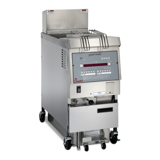
TECHNICAL
M A N U A L
OPEN FRYER
MODEL
CFE-410
CFE-420
(Electric)
M
R E G I S T E R W A R R A N T Y O N L I N E AT W W W. H E N N Y P E N N Y. C O M
R E G I S T E R W A R R A N T Y O N L I N E AT W W W. H E N N Y P E N N Y. C O M
Table of
Contents
Previous
Page
Next
Page
1
2
3
4
5
Advertisement
Table of Contents
Troubleshooting
Introduction
3
Troubleshooting
4
Need help?
Do you have a question about the CFE-410 and is the answer not in the manual?
Ask a question
Questions and answers
Related Manuals for Henny Penny CFE-410
Fryer Henny Penny CFE-415 Operation Manual
Narrow open fryer electric (94 pages)
Fryer Henny Penny CFE 415 Service Manual
Narrow open fryer electric (182 pages)
Fryer Henny Penny CFE-415 Operator's Manual
Open fryer (electric) (82 pages)
Fryer Henny Penny CFE-420 Technical Manual
Open fryer (51 pages)
Fryer Henny Penny Chick-fil-A Controls 500 Manual
Pressure fryers (56 pages)
Fryer Henny Penny HENNY PENNY 600 User Manual
Henny penny corp. fryer user manual (44 pages)
Fryer Henny Penny HENNY PENNY PFE-590 Technical Manual
Pressure fryer-electric (80 pages)
Fryer Henny Penny 520 User Manual
Henny penny corp. fryer user manual (15 pages)
Fryer Henny Penny 290 Troubleshooting Manual
Henny penny corp. fryer user manual (10 pages)
Fryer Henny Penny 291 Troubleshooting Manual
Henny penny corp. fryer user manual (10 pages)
Fryer Henny Penny 301 Operation Manual
Henny penny corp. fryer user manual (18 pages)
Fryer Henny Penny 580 Maintenance Manual
Henny penny corp. fryer user manual (27 pages)
Fryer Henny Penny FM03-681 Brochure
Henny penny corp fryers brochure (12 pages)
Fryer Henny Penny none Brochure
Henny penny corp. pressure fryers product brochure (12 pages)
Fryer Henny Penny PFG-600 Gas Specification Sheet
Pressure fryer (2 pages)
Fryer Henny Penny EEG-242 Technical Manual
Evolution elite gas open fryer (65 pages)
This manual is also suitable for:
Cfe-420
Table of Contents
Save PDF
Print
Rename the bookmark
Delete bookmark?
Delete from my manuals?
Login
Sign In
OR
Sign in with Facebook
Sign in with Google
Upload manual
Upload from disk
Upload from URL


Need help?
Do you have a question about the CFE-410 and is the answer not in the manual?
Questions and answers