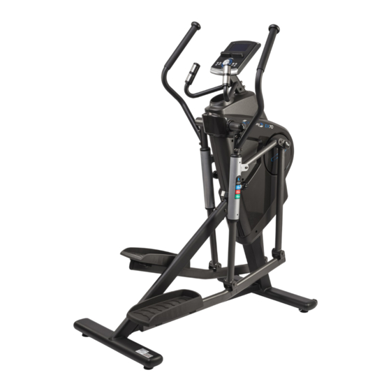
CARDIOSTRONG EX70 Assembly And Operating Instructions Manual
Elliptical cross trainer
For more information, please visit cardiostrong.com, sport-tiedje.com

Subscribe to Our Youtube Channel
Related Manuals for CARDIOSTRONG EX70


Summary of Contents for CARDIOSTRONG EX70
- Page 1 Assembly and operating instructions persons ) CSTEX70.04.02 Art.-No. CST-EX70-4 Elliptical cross trainer EX70...
- Page 2 EX70...
- Page 3 Dear Customer, Thank you for deciding for a high-quality training equipment of the brand cardiostrong®, the brand that makes athlete‘s hearts beat faster. cardiostrong® offers a wide range of home fitness equipment like elliptical cross trainers, ergometers, treadmills and rowing machines. cardiostrong® equipment is the optimal equipment for all those who want to train at home independent of goals and fitness level.
-
Page 4: Table Of Contents
4.4.3 Heart rate oriented programmes 4.4.4 Heart rate measuring 4.4.5 Watt controlled programme 4.4.6 User defined programme WARRANTY INFORMATION DISPOSAL ORDERING ACCESSORIES ORDERING SPARE PARTS 9.1 Service hotline 9.2 Serial number and model name 9.3 Parts list 9.4 Exploded drawing EX70... -
Page 5: General Information
GENERAL INFORMATION Technical data LCD display of speed in km/h training time in min training distance in km cadence (rotations per minute) calories burnt in kcal heart rate (when using the hand sensors or a chest strap) Watt resistance level Resistance system: electronic magnetic brake system Resistance level:... -
Page 6: Personal Safety
At the first signs of weakness, nausea, dizziness, pain, difficulty in breathing or other abnormal symptoms, stop your workout immediately and, if necessary, consult your physician. Without prior agreement from your authorized contract partner, opening the equipment is prohibited. EX70... -
Page 7: Electrical Safety
Electrical safety The equipment requires a 220 - 230V / 50 Hertz mains power supply. The equipment should be connected directly to a grounded plug socket only by means of the power cable supplied. The use of multi-socket adapters or similar is not recommended. Extension leads must comply with local electrical safety guidelines. -
Page 8: Assembly Instructions, Maintenance And Care
You should therefore immediately replace damaged or worn components. Please contact your contract partner in such a case. The equipment should no longer be used until it has been repaired. When needed, only use original cardiostrong® spare parts. Check the tightness of all screw connections once a month. -
Page 9: Faults And Troubleshooting
Faults and Troubleshooting The equipment runs through regular quality controls during production. Nevertheless, errors or malfunctions on the equipment may occur. Individual parts are often the cause of faults and replacement is usually sufficient. Please use the following overview to see the six most common errors and how to repair them. -
Page 10: Assembly
ASSEMBLY Package contents The package contains the parts represented in the illustration, including a power cable with mains plug. If one of the illustrated parts is missing, please contact your contract partner. EX70... - Page 11 Tools MULTI WRENCH TOOL W/ PHILLIPS SCREWDRIVER (65mm) ALLEN WRENCH (6 mm) SOCKET WRENCH (17 mm)
-
Page 12: Assembly Instructions
Assembly instructions EX70... - Page 13 Step 1 Assembly of levelling feet (1) See figures. Mount two levelling feet (27) under the front base (28). Please make sure that the levelling feet (27) are safely screwed in until the screw lines are no longer visible (see fig. 1). Note: When the machine does not stand even on the ground, please level it by means of the levelling feet (27).
- Page 14 Please make sure that the cables do not get clamped (see fig. 3 & 4). (4) Mount the front base (28) on the main frame (1), whereby the wheels point upwards. Tighten all four nylon nuts (76). 3 & 4 EX70...
- Page 15 Step 3 Assembly of rear base (1) Mount two levelling feet (27) at the bottom of the rear base (25) and please make sure that the machine is levelled (see fig. 5). Note: Five washers (66), five lock washers (65), five screws (87) are already pre-assembled at the back of the main frame (1) (see fig.
- Page 16 Tighten the screw (85) only after the first point of the assembly step 5. (3) Mount the support tube (30) on the rear base (25) by tightening another screw (85), a lock washer (65), and a washer (66) on top of the support tube (30). EX70...
- Page 17 Step 5 Tighten the screws (1) Tighten the two screws (85), two lock washers (65), and two washers (66) at the bottom of the support tube (30) (see fig. 14 & 15). (2) Tighten the four nylon nuts (76) on top of the front base (28) (see fig. 16). (3) Tighten the five washers (66), five lock washers (65), and five screws (87) in front of the rear base (25) (see fig.
- Page 18 (001a) and tighten the as- sembly with a washer (67), a cap (35), and a screw (94). (5) Remove the cable tie from the swinging arm (36). (6) Repeat the above mentioned steps for the other side. EX70...
- Page 19 Step 7 Assembly of swivel arms and crank bars (1) The swivel arms (47 & 48) are marked with “R” and “L”. (2) Two screws (M8 x p1.25 x 65 mm) (88) and two nylon nuts (M8 x p1.25) (75) are already pre-assembled in the swivel arm (48).
- Page 20 (3) Repeat the above mentioned steps on the other side. Step 9 Assembly of pedals (1) Place the pedal (55) on the pedal sup- port arm (58) and tighten it with four screws (86) (see fig. 29). (2) Repeat the above mentioned step on the other side. EX70...
- Page 21 Step 10 Assembly of the handlebar Note: Four washers (66), four lock washers (65), two screws (84), and two screws (85) are already pre-assemb- led on the main frame (1) (see fig. 30). (1) Remove the above mentioned screws and washers from the main frame (1). (2) Insert carefully the upper connecting cable (60) in the handlebar (32) (see fig.
- Page 22 (31) (see fig. 38). (6) Then slide the remai- ning cable in the hand- lebar (32) (see fig. 39). (7) Mount carefully the console (31) on the handlebar (32) by tigh- tening four screws (82) (see fig. 40). EX70...
- Page 23 Step 12 Assembly of the upper handlebar (1) The upper handelbars (44 & 45) are marked with “R” and “L” (see fig. 41). Note: Two screws (87) and two lock washers (65), and two washers (66) are already pre-assembled on the swivel arm (48) (see fig.
- Page 24 (2) Plug the adapter (63) in the socket to turn on the console. Transport Lift the rear base (25) with both hands and move carefully the machine to the desired place. Please make sure that the floor is even (see fig. 45). EX70...
- Page 25 Adjusting the stride length The elliptical cross trainer is equipped with three adjustable stride lengths from 18” (457 mm) to 23“ (584 mm). See fig. 46 for the following steps: (1) Loosen and pull out the right pin (54) to adjust the stride length. Pull the right telescopic bar (10) to the desired height (blue position for 23”, red position for 20”, green position for 18”).
-
Page 26: Operating Instructions
OPERATING INSTRUCTIONS Console display EX70... - Page 27 SPEED Displays your current pedal speed in km/h or mph. Displays your current pedal speed as rotations per minute (RPM). (a) Count up: When there is no target time set, TIME counts up from 0:00 to a maximum of 99:59 minutes. TIME (b) Count down: When you set a target time (from 1:00 to 99:00 in 1 minute increments), the console counts down to zero starting from the chosen target...
-
Page 28: Button Functions
That means that the hand pulse sensors do not detect correctly the signals. TOTAL RESET Turn on the console once again. Turn the button to choose a training mode or a resistance and to MODE +/- increase or reduce the function value. Confirm with MODE. EX70... -
Page 29: How To Turn On The Elliptical Cross Trainer
How to turn on the elliptical cross trainer (a) Please make sure that the power plug is correctly plugged in the wall socket. (b) Start pedalling and press any button to activate the console. The display lights up and a short signal sounds. - Page 30 Count down: When you set a target value for calories (from 10 to 99 in 10 CAL increments), the console counts down to 0.1 starting from the chosen target value for calories. F. Set the pulse Turn MODE to set the desired heart rate (from 30 to 230 BPM). Confirm with MODE. EX70...
-
Page 31: Pre-Set Programmes
Note: When you set a target pulse (30 to 230 BPM in 1 BPM increments), a signal sounds from the console once the current heart rate exceeds the target value during the training. G. Start the training (a) Press START/STOP to start the training. (b) During the training, you can turn MODE to choose a resistance level from 1 to 32. -
Page 32: Heart Rate Oriented Programmes
(c) Turn the MODE button to choose the heart rate programme P14. Press MODE to get to the programme. B. Set the target heart rate Turn MODE to set the target heart rate (55%, 75%, 90%, THR). Confirm with MODE. EX70... -
Page 33: Heart Rate Measuring
C. Set the time Turn MODE to set the desired time (from 1:00 to 99:00). Confirm with MODE. Note: Count up: When there is no target time set, TIME counts up from 0:00 to a maximum of 99:59 minu- tes. Count down: When you set a target time (from 1:00 to 99:00 in 1 minute increments), the console counts down to zero starting from the chosen target value for time. - Page 34 In order to achieve this training goal, a high intensity (approximately 90% of the maximum heart rate) with short, intense load is required, which is followed by a recovery phase in order to prevent muscle fatigue. EX70...
- Page 35 Example: For a 45-year-old man or woman, the maximum heart rate is 175 (220 - 45 = 175). • The fat burning target zone (55%) is at approximately 96 beats/min. = (220 - age) x 0.55. • The cardio target zone (75%) is at approximately 131 beats/min. = (220 - age) x 0.75.
-
Page 36: Watt Controlled Programme
(b) When you do not correctly grasp the hand pulse sensors with both hands and a few seconds pass without a pulse signal, the console turns off the pulse circle and the error “P” is displayed. Grasp the pulse sensors with both hands so that the pulse is displayed again. EX70... -
Page 37: User Defined Programme
4.4.6 User customised programme (P16) 1. Login setting (a) Press TOTAL RESET to turn the console on. That’s how you easily and quickly get to the POWER ON status. (b) Choose U1, U2, U3 or U4. (c) Enter your personal data for gender, age, height, and weight and confirm with MODE. -
Page 38: Warranty Information
WARRANTY INFORMATION cardiostrong‘s fitness equipment is subject to strict quality controls. However, if a fitness equipment purchased from us does not work perfectly, we take it very seriously and ask you to contact our customer service as indicated. We are happy to help you by phone via our service hotline. - Page 39 Warranty service Within the warranty period, equipment which develops faults as a result of material or manufacturing defects, will be repaired or replaced at our discretion. Ownership of equipment or parts of equipment which have been replaced is transferred to us. The warranty period is not extended nor does a new warranty period begin following repair or replacement under the warranty.
-
Page 40: Disposal
ORDERING ACCESSORIES Floor mat, size XL ArtNr. ST-FM-XL Chest strap ArtNr. ST1000 Silicone spray ArtNr. ST-1003 Chest-strap contact gel 250ml ArtNr. BK-250 Fitness equipment care kit ArtNr. HF-500 EX70... -
Page 41: Ordering Spare Parts
9:00 - 18:00 10:00 - 17:00 Serial number and model name Before assembling your equipment, find the serial number on the white sticker and enter it in the appropriate space. Serial number: Brand / category: Model name: cardiostrong elliptical cross trainer EX70-4... -
Page 42: Parts List
Crank Cover Right Upper Handlebar Left Cover Bearing (6905) Accessory Tray Left Pivoting Arm Right Cover Right Pivoting Arm EndCap Stride Length Adjustment Plate Rear Stabilizer Telescoping Bar Fixed Plate for Leveler Connection Plug (60x38) Leveler Left Adjustment Tube EX70... - Page 43 Description Qty. Description Qty. Right Adjustment Tube Screw (M5×20mm) Pull Pin Screw (M3×p0.5×16mm) Pedal Screw (M5×p0.8×15mm) Oval Plug (30x60) Bolt (M6×p1.0×12mm) Square Plug (20x40) Bolt (M8×p1.25×16mm) Support Arm Bolt (M8×p1.25×20mm) Sensor Wire Bolt (M8×p1.25×30mm) Upper Connection Wire Bolt (M8×p1.25×16mm) Middle Adaptor Connection Wire Bolt (M8×p1.25×65mm) Lower Adaptor Connection Wire Bolt (M8×p1.25×75mm)
-
Page 44: Exploded Drawing
Exploded drawing EX70... - Page 46 DISCLAIMER ©2010 cardiostrong® is a registered brand of the company Sport- Tiedje GmbH. All rights reserved. Any use of this trademark without the explicit written permission of Sport-Tie- dje is prohibited. Product and manual are subject to change. Technical data can be changed without advance notice.
- Page 48 Elliptical cross trainer EX70...
Need help?
Do you have a question about the EX70 and is the answer not in the manual?
Questions and answers