Extron electronics RGB 580xi AAP Series Setup Manual
Architectural adapter plate
Hide thumbs
Also See for RGB 580xi AAP Series:
- User manual (28 pages) ,
- User manual (4 pages) ,
- Specifications (2 pages)
Table of Contents
Advertisement
Quick Links
Setup Guide — RGB 580xi AAP
This guide provides basic instructions for an experienced
installer to set up and operate the Extron RGB 580xi AAP
and RGB 580xi CC AAP.
Installation
The AAP device should be cabled before attaching the AAP
device to a faceplate or wall plate.
C
Step 1 — Power down
Turn off or disconnect all equipment from power sources.
Step 2 — Connect the rear panel cables
Connect the cables to the AAP device's rear connectors.
Although the control cable, LED, and audio assemblies come prewired to the captive screw
N
connectors, any subsequent cable assembly replacement requires the following instructions.
Red
Black
Yellow
White
Pink
Orange
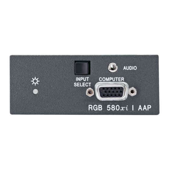
Example of AAP device rear connectors
Example of Cable Cubby AAP device rear connectors
To cable the captive screw connectors, refer to the following diagrams and orient the wires
according to the view angle of the captive screws. Use the Extron VGA and control cable
assembly and refer to the color of each wire for signal identification.
a
Control connector (J4) — This connector is used for contact closure and horizontal shift
signals. Wire the appropriate connector as shown below.
Horizontal shift
Horizontal shift ground (gray)
Horizontal shift
Contact closure
Contact closure
and RGB 580xi CC AAP Series
Installation and service must be performed by authorized personnel only.
3
Lt. Blue
1
2
Purple
Green
Gray
Brown
J4
J2
1
2
+
(green)
–
(brown)
+
(light blue)
–
(purple)
Pin 1
+
Horizontal shift
(green)
Horizontal shift ground (gray)
–
Horizontal shift
(brown)
+
Contact closure
(light blue)
–
Contact closure
(purple)
Pin 1
(Continued on reverse side.)
Advertisement
Table of Contents

Related Manuals for Extron electronics RGB 580xi AAP Series


Summary of Contents for Extron electronics RGB 580xi AAP Series
- Page 1 Setup Guide — RGB 580xi AAP and RGB 580xi CC AAP Series This guide provides basic instructions for an experienced installer to set up and operate the Extron RGB 580xi AAP and RGB 580xi CC AAP. Installation The AAP device should be cabled before attaching the AAP device to a faceplate or wall plate.
- Page 2 Inside Asia Only +81.3.3511.7656 FAX Inside China Only +971.4.2991880 FAX Inside USA / Canada Only Rev. A +1.919.863.1794 +31.33.453.4040 +65.6383.4400 +86.21.3760.1568 +1.714.491.1500 +1.919.863.1797 FAX +31.33.453.4050 FAX +65.6383.4664 FAX +86.21.3760.1566 FAX 11 09 +1.714.491.1517 FAX © 2009 Extron Electronics. All rights reserved.
Need help?
Do you have a question about the RGB 580xi AAP Series and is the answer not in the manual?
Questions and answers