Precor Experience Series Service Manual
Hide thumbs
Also See for Experience Series:
- Service manual (248 pages) ,
- Assembly manual (45 pages) ,
- Getting started manual (2 pages)
Table of Contents
Advertisement
Quick Links
Advertisement
Table of Contents
Troubleshooting

Related Manuals for Precor Experience Series


Summary of Contents for Precor Experience Series
- Page 1 Service Manual Experience™ Series P62 & P82 Consoles...
-
Page 2: Table Of Contents
Contents 1 Introduction Safety Guidelines Safety guideline you need to know and follow: 2 General Information Orientation Convention Controls and Indicators Motion Control Icons Console I/O Port Diagram P82 console P62 console Tools Fastener Torque Specifications Parts Cleaning Solutions Electrical Requirements Input Power Earth ground requirements 3 Operation Verification Verification Tests... - Page 3 Installing the Power Supply Installing the Console Updating the operating system software Registering the console System Settings Setup (Display & Workout Limits) TV Channel Guide Setup Media Adapter Console Setup Verify the console operation 5 Setup and Configuration About Topic Content Cloning the System Settings About Exporting the system settings...
- Page 4 Download the latest operating software version Installing the operating system software Rescue microSD card software install When to use the Rescue microSD card Rescue microSD card update procedure 7 Standard Service Menus About Service Access Codes How to Access the Service Menus Service menu access Touchscreen Calibration shortcut Debug Information Report shortcut...
- Page 5 9 Troubleshooting About Introduction To Troubleshooting Basic Steps Validate the customer reported issue: Verify the Input Power (Powered units only) Verify that the console is operating correctly Review the Error Log or CPA Event Log for any active error codes Verify (reproduce) the issue. Perform hardware validation diagnostic tests Verify Club Settings Verify that there are no new error codes...
- Page 6 Maintenance Schedule 11 Parts About P82 Console Parts P82 - Exploded View Diagram P82 - Parts List P62 Console Parts P62 - Exploded View Diagram P62 Parts List Appendix A : Edition Information Edition Copyright Appendix B : Notices and Safety Trademarks Intellectual Property Warranty...
-
Page 7: 1 Introduction
1 Introduction 1 Introduction If you are not a Precor certified servicer, you must not attempt to service any Precor Product. Call your dealer for service. WARNING: This service documentation is for use by Precor certified servicer pro- viders only. Personal injury can result from electrical shock and/or mechanical mov- ing parts. - Page 8 1 Introduction "Operation Verification" on page 14 "Standard Service Menus" on page 45 P82 Console...
-
Page 9: Safety Guidelines
Safety Guidelines WARNING: Only Precor certified servicers and technicians are permitted to service Precor products. Personal injury can result from electrical shock and/or mechanical moving parts. Safety guideline you need to know and follow: Read and follow all Warning notices to protect yourself from personal injury. - Page 10 1 Introduction Safety Guidelines Remove neck ties, and Do not wear loose clothing See Also "Safety Instruction" on page ii "Safety Notices" on page ii...
-
Page 11: 2 General Information
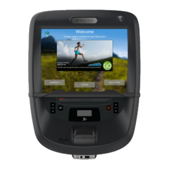
Orientation Convention 2 General Information The P62 and P82 are touchscreen consoles that provide the user interface and machine con- trol functions for the Precor 680, 780, and 880 line of cardiovascular equipment including ® ® Treadmills "TRM", Elliptical Fitness Crosstrainers™ "EFX ", Adaptive Motion Trainers... -
Page 12: Controls And Indicators
2 General Information Controls and Indicators Description Left Right Front Back Controls and Indicators Mechanical single and dual motion controls are used to vary the speed (resistance) and incline levels with values shown on displays located directly above the control. There is also other switches that control the media functions such as volume and TV channels. -
Page 13: Motion Control Icons
2 General Information Motion Control Icons Part Pause Incline or stride height* indicator Intensity or res- istance indicator* Volume up/dwn Channel up/dwn Mute Audio jack (Head- phone "HP" jack) USB port (char- ger/SW updates) Notes * Stride height indic- ator for AMT only. ** Incline indicator only on the dual- motion controls. -
Page 14: Console I/O Port Diagram
2 General Information Console I/O Port Diagram Motion Control ICONS Machine Type: ICON Metric(s) AMT: STRIDE HEIGHT, RESISTANCE UBK & RBK bikes: RESISTANCE Climber (CLB) : STEP RESISTANCE Note: Consoles are specific to a particular cardio machine type and cannot be used on a different type of machine. -
Page 15: P82 Console
2 General Information Console I/O Port Diagram P82 console CONNECTOR INTERFACE CONNECTOR/DEVICE LOCATION DESCRIPTION TYPE COMM Data Cable RJ45 eight pin modular (flat gray Data cable). Ethernet (LAN) Cable RJ45 eight pin modular (round black LAN cable). E-Stop Switch Cable Six pin strip, keyed. -
Page 16: P62 Console
2 General Information Console I/O Port Diagram CONNECTOR INTERFACE CONNECTOR/DEVICE LOCATION DESCRIPTION TYPE cable microSD mass storage .microSD memory card Notes: (1) Be careful to NOT connect the COMM Data Cable to the Ethernet input port which can damage the CPA board. (2) Do not connect cables to this port. -
Page 17: Tools
Parts IMPORTANT: Always purchase OEM replacement parts and hardware from Precor. If you use parts not approved by Precor, you could void the Precor Limited Warranty. Use of parts not approved by Precor may cause injury. Exploded View Diagram and Parts List... -
Page 18: Cleaning Solutions
This document provides a copy of the parts Exploded View Diagram and Parts Identification List that you can use as a quick reference, see "Parts" on page 79. It is recommended that ser- vicers go to the Precor Partner website Precor Partner Website to access the most current parts information. - Page 19 2 General Information Electrical Requirements Powered equipment (Treadmills): The power supply input power cables are connected to the line filter output power tabs. The earth ground wire is connected directly to the line filter chassis ground connector tab (a power supply adapter wire bundle is included with treadmill P82 installations).
-
Page 20: 3 Operation Verification
3 Operation Verification Verification Tests 3 Operation Verification This section provides a method of verifying the P82 operation. Check the P82 operation at the end of a maintenance procedure and when it is necessary to ensure that the console is oper- ating properly. - Page 21 Operation/Verification Test 3. Set the default channel, if applicable. Verify the movement controls: INCLINE and SPEED (TRM) INCLINE and RESISTANCE (EFX) STRIDE HEIGHT, RESISTANCE (AMT) RESISTANCE (UBK/RBK bikes, CLB) Verify the Heart Rate (HR) display: 1. Begin exercising on the equipment and grasp the left and right heart rate sensor handlebars.
-
Page 22: 4 Console Installation And Removal
4 Console Installation and Removal About 4 Console Installation and Removal About This procedure provides instructions to remove and install the P82 console. The console armor is designed to attach to cardio equipment bases ( including the EFX, TRM, AMT, and RBK/UBK bikes) that use a universal four bolt mounting plate. The number of inter- face cables that connect to the console will vary depending on the console type (standard or media adapter models) and the type of equipment. -
Page 23: P62 Console I/O Port Diagram
CONNECTOR INTERFACE CONNECTOR/DEVICE LOCATION DESCRIPTION TYPE Ethernet (LAN) Cable RJ45 eight pin modular (round black LAN cable). E-Stop Switch Cable Six pin strip, keyed. (TRM Only) RF (TV) Cable F-Type coax. HHHR Sensor Input Cable Four pin strip, keyed. Console DC Input Power Two pin plug. - Page 24 4 Console Installation and Removal Console I/O Port Diagram CONNECTOR INTERFACE CONNECTOR/DEVICE LOCATION DESCRIPTION TYPE COMM Data Cable Black color RJ45 eight pin modular (flat gray Data cable). Ethernet (LAN) Cable Silver color RJ45 eight pin modular connector (round black LAN cable. E-Stop Switch Cable Six pin strip, keyed.
-
Page 25: Removal Procedure
5. Remove the four 5/32" (4 mm) hex key console mounting bolts. Retain fastener hard- ware for installation. Note: All Precor equipment bases use a four bolt console mounting plate to secure the console. Treadmills require the rear dash cover to be removed to access the con- sole mounting fasteners. - Page 26 4 Console Installation and Removal Removal Procedure 7. Carefully remove the console-base interface cables. Disconnect the following cables, "P62 console I/O port diagram" on page 17 "P82 console I/O port diagram" on page 16. a. E-Stop Safety Switch cable (Treadmills only). b. COMM Data cable c.
-
Page 27: Installation Procedure
8. Remove the console from the base. Installation Procedure Installation Procedure Basic Installation Steps Installing the console entails completing each one of the following basic steps: "Locating the Interface Cables and Hardware" below (first time installations) "Installing the Power Supply " on page 23 (first time installations or replacement). - Page 28 4 Console Installation and Removal Installation Procedure the HDMI cable the IR Transmitter module. Cables and Hardware Ethernet LAN Cable RF Coax Cable Entertainment Plate (Accessory Jack) Power Cable AC/DC Adapter AC/DC Adapter (Self-powered machines) (Treadmills) Media Adapter cables/hardware IR Transmitter Cable* HDMI Cable* IR Transmitter Module*...
-
Page 29: Installing The Power Supply
2. For treadmill installations, remove the treadmill dash back cover to gain access to the console four mounting bolts, see the treadmill Service Manual (download from the Pre- cor Partner's (Precor Connect) website. 3. Remove the console lower bezel, see "P82 Console Cover Replacement" on page 62. - Page 30 4 Console Installation and Removal Installation Procedure 5. Install the following list of I/O interface cables. Hold the console while carefully routing and connecting the I/O interface cables, see "Console I/O Port Diagram" on page 16. a. RF (TV) Coax cable On P82 consoles, route the RF cable from the base mounting post upward through the console armor exiting through the upper left side, Connect the RF cable to the RF Tuner input...
- Page 31 to reach the console power input port c. HHHR cable On P82 consoles, route the HHHR cable from the base mounting post upward through the console armor exiting through the left side opening con- necting to the HHHR PCA sensor input port On P62 consoles, route the HHHR cable from the base mounting post upward through the console armor exiting through the bottom right side opening connecting to the HHHR PCA sensor input port...
- Page 32 Note: All Precor equipment bases use a universal four bolt mounting plate to attach the console to the base unit.
-
Page 33: Updating The Operating System Software
Registering the console ® This procedure provides instruction to register the console and base with Precor PBS (Preva Business Suite). The console must be connected to the internet to register the console. Note: This procedure assumes that the facility internet service provider has provided a wired Ethernet LAN connection. -
Page 34: System Settings Setup (Display & Workout Limits)
4 Console Installation and Removal Installation Procedure System Settings Setup (Display & Workout Limits) This procedure configures the Display and Workout Limits settings. 1. If you have a previously cloned System Settings USB drive or you can create one from another configured machine, then import the System Settings, see "Cloning the System Settings"... -
Page 36: 5 Setup And Configuration
5 Setup and Configuration About 5 Setup and Configuration About This topic provides information to help you copy "clone" the system settings,TV channel guide, and procedure to register the console. Topic Content "Cloning the System Settings" on the facing page "Cloning the TV Channel Guide" on page 33 "Scanning the TV Channel Guide"... -
Page 37: Cloning The System Settings
Cloning the System Settings About Cloning system settings allow you to easily copy system settings from one console (parent con- sole) to many consoles (child consoles). This method copies the Connectivity, Display, Media, and Workout Limits settings. Both the parent and child consoles must be mounted on the same equipment type. - Page 38 5 Setup and Configuration Cloning the System Settings IMPORTANT: .Return to the "Welcome" banner before removing the USB drive.
-
Page 39: Cloning The Tv Channel Guide
Cloning the TV Channel Guide only copies the TV Channel Guide list, the TV signal and format settings are not copied, refer to the console Owner's Manual and/or the Networked Fit- ness Media Adapter Guide (downloadable from the precor.com console product website) for more information. - Page 40 5 Setup and Configuration Cloning the TV Channel Guide 6. Go to the Channel Guide menu and verify that the channel guide list was correctly imported (select TV Settings > Channel Guide). 7. Return to the "Welcome" banner and then remove the USB drive. IMPORTANT: .Return to the "Welcome"...
-
Page 41: Scanning The Tv Channel Guide
Scanning the TV Channel Guide About The console provides a Channel Guide SCAN function that builds a new TV Channel Guide list from the TV RF input signal. If you do not have access too or cannot create a channel guide cloning USB drive then the SCAN function is the next best available solution to create a new channel guide. -
Page 42: Registering The Console
LAN network is operating. Register the console menu: System Settings > Connectivity ® This procedure provides instruction to register the console and base with Precor PBS (Preva Business Suite). The console must be connected to the internet to register the console. ® ®... - Page 43 4. Select Register Equipment to begin the console registration process. Follow the ® screen prompts and specify the facility PBS (Preva Business Suite) username and password (provided by dispatch or the facility operator). 5. The next screen will prompt you to specify the following registration information: :location code (provided by dispatch) base serial number (machine model/serial number bar code label) friendly name (ask facility operator for the friendly name, must be unique for each...
-
Page 44: Media Adapter Consoles
Setup and configuration For media adapter setup and configuraiton information, refer to the Networked Fitness " Media Adapter Guide ". The guide can be downloaded from the Precor.com P62 or P82 console web site: Media Adapter Guide PDF download link:... -
Page 45: 6 System Software
6 System Software About The console operating system software is also referred to as the "Preva Operating System" software. This topic will show you how to find the current software versions and how to update the console software. You can manually update the software or configure the console to automatically update the software (this requires the console to be registered and connected to internet). -
Page 46: How To Find The Operating & Component System Software Versions
File System software version How to Update the console operating system software Download the latest operating software version 1. Login to the Precor Partner's (Precor Connect) website and navigate to the "SOFTWARE DOWNLOAD CENTER" website (select Service Documentation > Con- sole Software). -
Page 47: Installing The Operating System Software
OK. Installing the operating system software 1. On a USB flash drive, create a folder named “precor” in the root directory. 2. Move the downloaded software zip file to the USB flash drive by right-clicking the zip file, selecting “extract all.”, browsing to the "precor"... -
Page 48: Rescue Microsd Card Software Install
6 System Software Rescue microSD card software install Rescue microSD card software install When to use the Rescue microSD card Typically the rescue microSD card is required when the OS software has become corrupted and the console fails to power-up to the Welcome banner. Only use the rescue microSD card as a last resort, reseting the console and/or updating the OS software have failed to fix the problem. - Page 49 P62 Rescue mircoSD software install 6. A successful reboot will show a blue boot-up progress status bar at the bottom of the dis- play. If the progress status bar does not show, repeat the Recovery microSD card boot- up steps. A successful installation will finish with a green check mark , approximately 7-8 minutes.
- Page 50 12. Re-register the console; a. First you will need to contact Precor customer service (Ph: +1 (800) 347- 8404and have the console registration removed from PBS, b. Then do the steps to re-register the console.
-
Page 51: 7 Standard Service Menus
About The P62 & P82 support the Service menu and Club Settings Standardized Service menus used across Precor cardio product lines: Service (51765761: Service menu provides access to all available equipment service menus, used by service technicians to service and maintain the equipment. -
Page 52: Service Menu Access
7 Standard Service Menus How to Access the Service Menus Service menu access Steps 1. Make sure the console is set to the Welcome banner. 2. Press and hold the VOL down key while pressing CH up >CH down > CH down > CH 3. -
Page 53: Debug Information Report Shortcut
7 Standard Service Menus Navigating the Service Menus 3. Touch the designated display positions and follow prompts to complete the touchscreen calibration. Debug Information Report shortcut Console shortcut to download an event log debug information report. Steps 1. Make sure the console is set to the Welcome banner. 2. -
Page 54: P62 Consoles
7 Standard Service Menus P62 consoles CONSOLE KEY FUNCTION/DESCRIPTION BACK softkey • Use the touchscreen BACK softkey to return to the previous menu display. • Continue selecting the BACK softkey to exit the service software. PAUSE hardkey Stop a running diagnostic test. P62 consoles The P62 console uses a combination of touchscreen softkeys , icons, and keypad hardkeys to select and navigate thru the service and diagnostics menus. -
Page 55: Service Menu (51765761)
7 Standard Service Menus Service Menu (51765761) CONSOLE KEY FUNCTION/DESCRIPTION PAUSE hardkey Stop a running diagnostic test. Service Menu (51765761) Access code: 51765761 (see"" on page 45) The Service menu provides access to all available equipment service menus, used by service technicians to service and maintain the equipment. -
Page 56: About Menu
(Preva Business Suite). Partition Configuration menu: Settings > Partition Configuration menu: OEM use only, contact Precor Customer Service for information. (No) Available menu: Settings > No Available Updates or Available Updates Updates menu No Available Updates: No available software updates can be read from the USB flash drive. -
Page 57: Equipment Usage Menu
7 Standard Service Menus Service Menu (51765761) ABOUT MENU DESCRIPTION The CPA Event Log only contains the machine maintenance and troubleshooting error event codes that are described in the " Error Code Troubleshooting Guide ", see "Error Code Troubleshooting Guid e ". -
Page 58: Maintenance Menu
7 Standard Service Menus Service Menu (51765761) EQUIPMENT USAGE DESCRIPTION MENU Cumulative Workout menu: Equipment Usage > Cumulative Workout Distance Hours Machine total workout hours. Cumulative Workout menu: Equipment Usage > Cumulative Workout Distance Distance Machine total workout distance. Cumulative Workout menu: Equipment Usage >... -
Page 59: System Settings Menu
7 Standard Service Menus Service Menu (51765761) MAINTENANCE DESCRIPTION MENU A belt rating of 0 or 1 will cause a blue pulsing ASL light indicating that there is a problem with the running belt/deck and requires ser- vicing or replacement. Important: Reset the Belt Rating after replacing with a new run- ning belt and deck (select Replace). - Page 60 ® ® » Preva Server menu: System Settings > Connectivity> Preva Server Specifies Precor Preva server URL (na.preva.com). Display menu menu: System Settings > Display Console default display configuration settings: language, units, standby delay, .browser and news reader on/off. » Default Language menu: System Settings > Display > Default Language Default: English Specifies the default language.
- Page 61 7 Standard Service Menus Service Menu (51765761) SYSTEM SETTINGS DESCRIPTION MENU Specifies the default measurement units. » Standby Mode menu: System Settings > Display > Standby Mode Delay Delay Range: 5, 10, 15. 30, 60 minutes Default: 15 minutes Specifies the idle wait time before entering standby mode. » Browser menu: System Settings >...
- Page 62 7 Standard Service Menus Service Menu (51765761) SYSTEM SETTINGS DESCRIPTION MENU » Extensive Scan menu: System Settings > TV Settings > Extensive Scan Default: OFF Searches all available channel sources. » Closed Captioning menu: System Settings > TV Settings > Closed Captioning Default: On Switches close caption feature ON/OFF.
-
Page 63: System Tests Menu
Default: ON Sets Auto Stop to On or Off. Register Equipment menu:System Settings > Register Equipment menu ® Register console and equipment with Precor Preva Business Suite "PBS". Required information to register the equipment: Location code Precor technician account name and password... - Page 64 7 Standard Service Menus Service Menu (51765761) menu: Service menu (51765761) > Settings > System Settings > System Tests. Machine diagnostics tests to verify system hardware operation. SYSTEM TESTS TEST DESCRIPTION MENU AMT Stride Pos- (AMT only) ition Test menu: System Tests > AMT Stride Position Test Verifies the stride movement: Low Radius.
- Page 65 7 Standard Service Menus Service Menu (51765761) SYSTEM TESTS TEST DESCRIPTION MENU range, levels 1 to 20. A/D: Lift potentiometer analog to digital voltage value. Glitches: number of sticking lift motion. Volts (DC): lift motor voltage. Auto Stop Test menu: System Tests > Auto Stop Test Test parameters;...
-
Page 66: Club Settings Service Menu (5651565)
7 Standard Service Menus Club Settings Service Menu (5651565) SYSTEM TESTS TEST DESCRIPTION MENU Tests the movement controls LCD numeric displays. Heart Rate menu: System Tests > Heart Rate Test Tests the handlebar unfiltered, filtered, and pulse heart rate. Grasp the grips to test the hand held heart rate. -
Page 67: 8 Replacement Procedures
8 Replacement Procedures About There are currently no authorized serviceable electronic parts for the P62 and P82 consoles. If there is a hardware failure, please contact Precor Customer Service (ph. +1 (800) 347-8404) for proper repair disposition. Available Replacement Procedures "P82 Console Cover Replacement" on the next page "Console Installation and Removal"... -
Page 68: P82 Console Cover Replacement
8 Replacement Procedures P82 Console Cover Replacement P82 Console Cover Replacement About This topic provides instructions to removes and installs the P82 console covers. Item Description Reading Rack Lower Vent Bezel Chin (HP/USB Jack) Upper Access Panel Rear Cover HHHR board Procedure Review entire procedure before starting. - Page 69 1. Remove the reading rack a. Remove the two #2 Phillips screw fasteners and carefully lift the reading rack off the front cover. Retain fastener hardware for installation. 2. Remove the lower vent bezel a. Use your fingers to carefully unsnap the bottom left and right edges of the bezel from the bottom of the front cover.
- Page 70 8 Replacement Procedures P82 Console Cover Replacement 4. Install the lower vent bezel a. Place the bezel over the console weldment so that the bezel top clips fit under the rear cover edge. Then press down near the bottom left and right sides of the bezel to snap the mounting clips into place.
-
Page 71: 9 Troubleshooting
9 Troubleshooting About 9 Troubleshooting About This section contains troubleshooting information to help you identify, isolate, and resolve com- ponent and system issues. Review the Introduction To Troubleshooting section below to learn about the troubleshooting process, troubleshooting best practices, and other pertinent information that will help you effi- ciently troubleshoot issues and return the equipment to service. -
Page 72: Verify The Input Power (Powered Units Only)
You can then refer to Error Code Troubleshooting Guide to help resolve the issue. Also, when calling Precor cus- tomer service for assistance, refer to the Error Log or CPA Event Log for additional inform- ation to help the representative resolve the issue. -
Page 73: Verify (Reproduce) The Issue
9 Troubleshooting Basic Steps Verify (reproduce) the issue. Operate the unit in normal user mode and attempt to reproduce the reported failure Determine if the error is a repeatable or intermittent type failure Make note of any additional observations (noises, vibrations, etc.) that occur at the time of the failure which may then be used to help resolve the issue. -
Page 74: Standard Error Codes
Standard Error Codes About There is a set of standard error codes implemented across Precor exercise equipment. Error codes are system generated error codes designed to detect and report fault conditions. Each error code is associated with a particular system or component fault condition. The main-... -
Page 75: Viewing Error Codes (Error Log & Event Log)
Viewing Error Codes (Error Log & Event Log) Error event codes are logged, stored, and viewed in either the Error Log or CPA Event Log menus depending on the console model, see Error Log & CPA Event Log: TIP: Deleting Error Codes from the Error Log: Press and hold the PAUSE/RESET key for a minimum of 6 seconds to open the Error Log and view all logged error codes. -
Page 76: Cpa Event Log
You can then refer to Error Code Troubleshooting Guide to help resolve the issue. Also, when calling Precor cus- tomer service for assistance, refer to the Error Log or CPA Event Log for additional inform- ation to help the representative resolve the issue. - Page 77 The P62, P80, and P82 CPA Event Log provides the same error code data found in the P10, P30, and P30i Error Log in addition to the event date & time stamp information. The "CPA ERROR" identifier in the error code output message indicates that this is a machine fault error code that can be used along with the Error Code Troubleshooting Guide to help resolve the issue.
-
Page 78: Active Status Light (Asl)
9 Troubleshooting Active Status Light (ASL) Active Status Light (ASL) (Only applies to machines that support the ASL feature) About The Active Status Light (ASL) is a service and maintenance status light that provides a visual indication of the machine operational status. The current implementation supports four states: 1) Solid blue - indicates normal operation, 2) pulsing blue - indicates preventative maintenance is required;... -
Page 79: Asl Overview
ASL Overview An externally visible indicator of the current machine operational status. There are four supported states: 1) solid blue - indicates normal operation, 2) pulsing blue - indicates preventative maintenance is required; 3) solid yellow - indicates an error has occurred but the machine is useable;... -
Page 80: Asl States
9 Troubleshooting Active Status Light (ASL) Maintenance counter operation: The counter starts at 1000 miles and counts down the miles of active use to 0 miles. When the counter reaches zero, the ASL will begin pulsing blue indicating preventative maintenance is due. Maintenance counter operation: The counter starts at 250 hours and counts down the hours of active use to 0 hours. -
Page 81: Asl Settings And Functions
ASL State DESCRIPTION due. Yellow Solid Indicates an error has occurred, was self-corrected and the machine can be used. The fault can be cleared. Yellow Pulsing There is a current non-recoverable fault condition, there is a loss of a major function and the machine is out-of-service. Machine service is required. - Page 82 9 Troubleshooting Active Status Light (ASL) Viewing the current ASL state The current ASL state (solid blue, pulsing blue, solid yellow; or pulsing yellow) can be viewed using the service menu ACTIVE STATUS LIGHT parameter. P62, P80, and P82 consoles: Access Club Settings (5651565) >...
- Page 83 Clearing the solid yellow ASL state P62, P80, and P82 consoles: 1. On P62, P80, and P82 consoles, the Maintenance > Operating Condition parameter must be reset from the Inspect condition to the Normal condition. After resetting the Operating Condition to Normal, the ASL state will change from solid yellow to the solid blue state.
-
Page 84: 10 Preventive Maintenance
About Preventative maintenance is proven to extend the life of the equipment, improve the user experience, and keep maintenance problems and service calls to a minimum. Precor recom- mends the following preventative maintenance schedule. IMPORTANT: It is the responsibility of the owner to maintain equipment in accord- ance with the Precor recommended preventative maintenance schedule. -
Page 85: 11 Parts
Exploded View Diagram and Parts Identification List information. Precor Partner Website IMPORTANT: Always purchase OEM replacement parts and hardware from Precor. If you use parts not approved by Precor, you could void the Precor Limited Warranty. Use of parts not approved by Precor may cause injury. -
Page 86: P82 Console Parts
11 Parts P82 Console Parts P82 Console Parts P82 - Exploded View Diagram... -
Page 87: P82 - Parts List
P82 - Parts List... -
Page 88: P62 Console Parts
11 Parts P62 Console Parts P62 Console Parts P62 - Exploded View Diagram... -
Page 89: P62 Parts List
P62 Parts List... -
Page 90: Appendix A : Edition Information
No part of this manual may be reproduced in any form or by any means (including electronic storage and retrieval or translation into a foreign language) without prior agreement and writ- ten consent from Precor Incorporated as governed by United States and international copy- right laws. -
Page 91: Appendix B : Notices And Safety
Precor shall not be liable for errors or for incid- ental or consequential damages in connection with the furnishing, use, or performance of this document or of any information contained herein. - Page 92 Appendix B : Notices and Safety instructions. Warning WARNING notice denotes a hazard. It calls attention to an operating procedure, practice, or the like that, if not correctly performed or adhered to, could result in per- sonal injury or death. Do not proceed beyond a WARNING notice until the indicated conditions are fully understood.
Need help?
Do you have a question about the Experience Series and is the answer not in the manual?
Questions and answers