Table of Contents
Advertisement
Quick Links
Installation/Owner's Manual
Use this manual for circuit board 1601-010 Revision W or higher.
CO
NF
AN
OR
SI /U
M S
L- 32
TO
CA
CE
N/
CS
RT
5
A C2
IF IE
VE
D
TO
H IC
2. 2
U LA
NO
CL
AS
. 24
533
82
S
R
G AT
7
M OD
E O
EL
PE
R AT
SE
O R
RI
HP
AL
VO
LT
S
AM
PS
M AX
PH
GA
AS
TE
E
Do
LO
AD
60
or Ki
Hz
ng
, In
c. ,
In gl
ew
oo
d,
CA
M o
v i n
S e
g G
r i o
a t e
u s
K E
E P
I n j
C a
w it
C L
u r y
n C
h o
E A
D o
u t
p r io
R !
o r
a u
n o
in
G a
t le
r w
D e
s e
th e
te
t c
a r n
T h
h il
m a
a t h
g a
in g
is
te
d r e
y m
e n
.
P e
a r e
n o
tr a
o v
d e
a .
p e
e a
s tr
n c
e is
r a te
t a
ia n
n y
s m
fo r
th e
ti m
u s
v e
g a
e
t u
h ic
te
s e
le s
o r
s e
o n
p la
p a
ly .
y
r a te
e n
tr a
n c
e .
Date Installed:
Installer/Company Name:
Phone Number:
Leave Manual with Owner
Conforms To UL STD 325
Certified To CSA STD C22.2 # 247
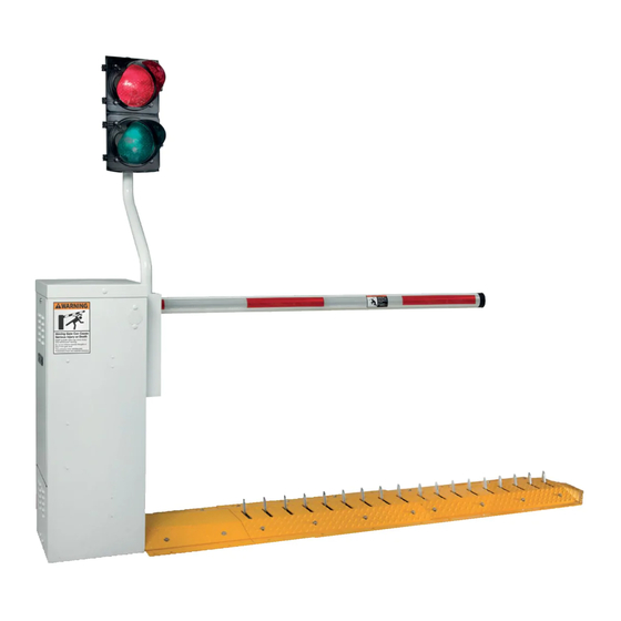
Barrier Gate Operator with Auto Spike System
THIS PRODUCT IS TO BE INSTALLED AND SERVICED BY A TRAINED GATE SYSTEMS TECHNICIAN ONLY.
Visit www.dkslocator.com to find a professional installing and servicing dealer in your area.
Circuit Board
Serial Number
and Revision Letter:
Copyright 2018 DoorKing, Inc. All rights reserved.
1603
1603
1603
1603-065-F-8-18
Copyright 2009 DoorKing, Inc. All rights reserved.
Advertisement
Table of Contents

Related Manuals for DoorKing 1603


Summary of Contents for DoorKing 1603
- Page 1 Installer/Company Name: Circuit Board Serial Number Phone Number: and Revision Letter: Leave Manual with Owner Copyright 2018 DoorKing, Inc. All rights reserved. Conforms To UL STD 325 Certified To CSA STD C22.2 # 247 Copyright 2009 DoorKing, Inc. All rights reserved.
- Page 2 Type C - Inherent force limiting, inherent adjustable clutch or inherent pressure relief device. Type D - Actuating device requiring constant pressure to maintain opening or closing motion of the gate. * B1 and B2 means of entrapment protection must be MONITORED. Safety - 1 1603-065-F-8-18...
- Page 3 Spike Warning and Illumination 21” is typical for most installations. It is extremely important that traffic spikes are installed in an area that is illuminated and clearly marked with spike warning signs (DoorKing’s model 1615 illuminated warning sign kits). 1603-065-F-8-18 Safety - 2...
- Page 4 Keep all debris away from operator housing vents and off of arm. Contact your service dealer for any maintenance or repairs. • Vehicular operators can produce high levels of force, it is important that you are aware and eliminate possible HAZARDS; Pinch Points, Entrapment Areas, Absence of Controlled Pedestrian Access, Traffic Backup. Safety - 3 1603-065-F-8-18...
-
Page 5: Quick Guide: Terminal Descriptions
SW 1, switch 8. This input is used when sequencing the When switch 8 is ON, the 1603 with a slide or swing gate operator in function of this input is PAMS applications. This input is only active identical to terminal 6. - Page 6 P/N 1610-240 DoorKing, Inc. reserves the right to make changes in the products described in this manual without notice and without obligation of DoorKing, Inc. to notify any persons of any such revisions or changes. Additionally, DoorKing, Inc. makes no representations or warranties with respect to this manual. This manual is copyrighted, all rights reserved.
-
Page 7: Table Of Contents
TABLE OF CONTENTS IMPORTANT SAFETY INFORMATION Safety-1-3 QUICK GUIDE - TERMINAL DESCRIPTIONS Quick Guide-1 SPECIFICATIONS FOR 1603 Previous Page SECTION 1 - INSTALLATION OF OPERATOR Operator Positioning and Conduit Requirements Concrete Pad Requirements Mount Operator Dual Operator Installation (Primary/Secondary) SECTION 2 - WIRING... -
Page 8: Section 1 - Installation Of Operator
SERIAL VOLTS PHASE AMPS 60 Hz PROCEED ONLY WHEN MAX GATE LOAD DoorKing, Inc., Inglewood, CA SPIKES ARE DOWN NO PEDESTRIANS IN TRAFFIC LANE Conduit Area Moving Gate Can Cause Note: Operator shown mounted on the LEFT side (preferred). Serious Injury or Death KEEP CLEAR! Gate may move at any time without prior warning. -
Page 9: Concrete Pad Requirements
AMPS 60 Hz MAX GATE LOAD pad with the mounting flange using Sleeve Anchor DoorKing, Inc., Inglewood, CA 1/2” x 3” minimum sleeve anchors (not supplied). Moving Gate Can Cause Serious Injury or Death KEEP CLEAR! Gate may move at any time without prior warning. -
Page 10: Dual Operator Installation (Primary/Secondary)
Interconnection Cable Orange Orange Sold separately from DoorKing. 4 wires used (8 - 18 AWG wires total). When using Reverse Loops: DIP-Switch settings: SW 1, switch 4 is OFF. SW 1, switch 5 is OFF. SW 1, switch 8 is OFF. Set other DIP-switches based on gate operation preferences. -
Page 11: Section 2 - Wiring
External Power DO NOT power up and cycle the operator until Disconnect the “DIP-Switches” have been set for the 1603 Switch model (See pages 18 and 19). Note: A separate power disconnect The operator will not function properly unless the switch may be needed in your area. -
Page 12: Main Terminal Description
Function is dependent on the setting This input is used when sequencing the of programming SW 1, switch 8. 1603 with a slide or swing gate operator in When switch 8 is ON, the PAMS applications. This input is only active function of this input is after a MOMENTARY UP input is received. -
Page 13: Control Wiring
2.4 Control Wiring for Single/Primary Operator TIME DELAY DoorKing Access Control System (Model 1833, 1835, 1837 or LOOP 1838) tracker system can be connected. This system can keep track of gate operator cycle count, shorted c k e Gate Operator... -
Page 14: Section 3 - Installation Of Auto Spike System
( O p i o n t i o n a l i k e e c t i o n UP Position Traffic Direction RETRACTED Position CORRECT Spike Positions The spikes will retract towards oncoming traffic. 1603-065-F-8-18... -
Page 15: Test Spikes When Operator Positioned On Left Side
..spikes can now be adjusted to the correct UP position as shown. Correct UP Position Traffic Direction p r o c k e ..replace the chain back onto lower sprocket and tighten both turnbuckles after spikes have been adjusted to the correct position. 1603-065-F-8-18... -
Page 16: Test Spikes When Operator Positioned On Right Side
The spikes can also be adjusted to the correct position at this time (see below) Spike Adjustment Traffic Direction Correct UP Position RETRACTED Position Adjust spikes as shown. 1603-065-F-8-18... -
Page 17: Secure Each Section To Concrete
The ramps will have to be unbolted and the tunnel will need to have the debris cleaned out every so often to keep the spikes in good working condition. The sleeve anchors mounted inside the tunnel will also need to be checked for looseness and repaired when necessary. 1603-065-F-8-18... -
Page 18: Section 4 - Loop Detector Lane Setups
Loop detector wiring shown is for DoorKing model 9409 Dual Channel and 9410 Single Channel plug-In loop detectors only. If using other loop detectors refer to the separate Loop Information Manual for installation instructions, loops/preformed loops and wiring diagrams. -
Page 19: Exit Lane Only
Activation of the down loop will cancel timer countdown. Useful when the automatic exit loop has been activated but vehicle does not move forward to activate the down loop. The arm will remain UP. Timer will time out and lower the arm without the down loop being activated. 1603-065-F-8-18... -
Page 20: 2-Way Traffic Lane
Helps increase distance move forward to activate the down loop. The arm will remain UP. Timer will and time between vehicles. time out and lower the arm without the down loop being activated. 1603-065-F-8-18... -
Page 21: Ticket Spitter Entry Lane
The arm will remain UP. Timer will time out Helps increase distance and lower the arm without the down loop being activated. and time between vehicles. 1603-065-F-8-18... -
Page 22: Operator Timer On Entry Lane (No Down Loop)
Reverse Loop Note: The reverse loops will prevent the arm from closing on a Speed Bump vehicle remaining in the arm’s pathway. The timer will restart the countdown any Helps increase distance time the reverse loop gets activated. and time between vehicles. 1603-065-F-8-18... -
Page 23: Section 5 - Arm Installation
BOTH sides of arm. 14 Ft. Arm Arm UP when Spikes are DOWN Cover Note: To install folding aluminum arm, Test hub UP and DOWN refer to instruction sheet supplied in position before installing arm. aluminum folding arm kit. P/N 1601-310 1603-065-F-8-18... -
Page 24: Section 6 - Adjustments
See page Set the DIP-switches on the circuit board to the desired setting. See switch settings informa- SW 1 tion on the next 3 pages. DoorKing Plug-In 9410 Loop Detectors SW 1 (Sold separately) Note: SW 2, switch 1 Power... -
Page 25: Dip-Switch Sw 1 And Sw 2 Settings
Relay 1 Activation Relay activates when the UP loop detector (DoorKing plug-in detector only) senses a vehicle presence. Up Input will raise arm and/or reset the down timer. Input will not lower the arm. Up Input Function Up Input will raise arm if it is down, or will lower arm if it is up. - Page 26 “Next Car’s” down loop to be activated. 1st Car Next Car When “Next Car” activates then clears Note: down loop, arm will lower. If an UP command is given while the arm is lowering, the arm will raise. 1603-065-F-8-18...
- Page 27 Note: If an UP command is given while the arm is lowering, the arm will raise. Valid UP command given Access Control Device 1603-065-F-8-18...
-
Page 28: Magnetic Limit Adjustment
1/8 turn. REVERSE 1601 SENSITIVITY POWER Repeat the adjustment as needed to find a SW 2 satisfactory setting. REVERSE SENSITIVITY DOWN LOOP Min Max NC NO 1 2 3 4 5 6 7 8 9 10 11 12 13 14 1603-065-F-8-18... -
Page 29: Manual Operation Of Arm And Spikes
C r a r a g t l e a r e w i t S t o t h e t r a i a n s t r 1603-065-F-8-18... -
Page 30: Section 7 - Optional Convenience Open System
This system is not designed to maintain continuous barrier operation; rather it provides a convenient method to open the arm once during adverse conditions. If continuous barrier and access control system operation is required, refer to the DoorKing Model 1000 Inverter / Backup Power System. -
Page 31: Dc System Wire Schematic
UP position. DC ON/OFF Power Switch Red/White Black/White Orange Yellow TIME DELAY LOOP SW 1 1601 POWER SW 2 REVERSE DOWN LOOP NC NO 1 2 3 4 9 10 11 12 13 1603-065-F-8-18... -
Page 32: Section 8 - Optional Accessories Installation
8.1 Contact Sensor (Reversing Edge) In addition to the electronic reversing device (ERD) an optional electric reversing edge may be installed offering additional protection to the arm, operator and obstruction. Available from DoorKing to fit all arm lengths. Turn operator power OFF. Remove Cover. -
Page 33: Fan Kit
ON when the temperature rises above 90°F inside the S t a E x i housing, and turns the fan OFF when the temperature A i r drops below 90°F. Keep intake vents clear of debris. 1603-065-F-8-18... -
Page 34: Heater Kit
ON when the temperature drops below 40°F inside the housing, and turns the heater OFF when the temperature rises above 40°F inside the housing. - Turns the heater off. - Turns the heater on continuously. The heater will become VERY HOT when running continuously. 1603-065-F-8-18... -
Page 35: Section 9 - Technical Instructions
Check set screw for tightness. ✓ ✓ Check electric reversing edges and photo-cells for proper External Reverse Device(s) operation. ✓ Perform a complete system check. Include all reversing devices, Complete System loops, access system devices, Fire Dept. access devices, etc. 1603-065-F-8-18... -
Page 36: Diagnostics Check
For more information refer to the loop detector instruction sheet and the DoorKing Loop and Loop Detector Information Manual. Check that there are no shorted or open control wires from the keying devices to the gate operator. If a keying device fails to open the arm, momentarily jumper across terminals 6 and 14 on the control board terminal. - Page 37 Check the batteries for proper voltage, replace if necessary. power outage. • Replace the 1473-010 Back-up control board. Operator has • The main terminal #5 250 mA power has been exceeded. intermittent Check total amp draw of connected device(s). functionality problems that vary. 1603-065-F-8-18...
-
Page 38: Accessories Parts List
- Checks the integrity of ground loops. P/N 9401-045 Reverse Edge - Installs on the bottom of the aluminum arm. P/N 8080-016 - 6 ft. Available from DoorKing to fit all arm lengths. Photo Cell - Prevents arm from lowering on vehicles or pedestrians. P/N 8080-018 Time Clock - 7 clock, used to automatically open gate at pre-set time, fits inside operator. -
Page 39: Wiring Schematics
POWER REVERSE SENSITIVITY DOWN LOOP NC NO Current Sensor 1 2 3 4 5 6 7 8 9 10 11 12 13 14 Chassis Ground Power Black Black NEU HOT 115 VAC Neutral Yellow Orange Ground AC Power UP/Auto/Down 1603-065-F-8-18... - Page 40 Current Sensor 1 2 3 4 5 6 7 8 9 10 11 12 13 14 Chassis Ground Power Black Black 115 VAC Neutral NEU HOT Purple Green White Orange Yellow Purple Blue Ground AC Power DC Power UP/Auto/Down 1603-065-F-8-18...
- Page 41 1603-065-F-8-18...
- Page 42 THIS PRODUCT IS TO BE INSTALLED AND SERVICED BY A TRAINED GATE SYSTEMS TECHNICIAN ONLY. Visit www.dkslocator.com to find a professional installing and servicing dealer in your area. www.doorking.com DoorKing, Inc. 120 S. Glasgow Avenue Inglewood, California 90301 U.S.A. Phone: 310-645-0023 Fax: 310-641-1586 Copyright 2009 DoorKing, Inc. All rights reserved.
Need help?
Do you have a question about the 1603 and is the answer not in the manual?
Questions and answers