Table of Contents
Advertisement
Quick Links
Instruction Manual
Model 4420
VW Crackmeter
No part of this instruction manual may be reproduced, by any means, without the written consent of Geokon, Inc.
The information contained herein is believed to be accurate and reliable. However, Geokon, Inc. assumes no responsibility
for errors, omissions, or misinterpretation. The information herein is subject to change without notification.
Copyright © 1986-2017 by Geokon, Inc.
Doc Rev U 11/27/2017
Advertisement
Table of Contents

Related Manuals for Geokon 4420


Summary of Contents for Geokon 4420
- Page 1 Model 4420 VW Crackmeter No part of this instruction manual may be reproduced, by any means, without the written consent of Geokon, Inc. The information contained herein is believed to be accurate and reliable. However, Geokon, Inc. assumes no responsibility for errors, omissions, or misinterpretation.
- Page 3 Upon examination by Geokon, if the unit is found to be defective, it will be repaired or replaced at no charge. However, the WARRANTY is VOID if the unit shows evidence of having been tampered with...
-
Page 5: Table Of Contents
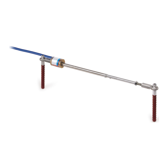
2.2.2 Installation using Weldable Fixtures ......................4 2.2.3 Installation using Groutable Anchors ......................5 2.2.4 Installation using Expansion Anchors ......................6 2.2.5 Special note regarding installation of Models 4420-1-3MM (.125”), 4420-1-12.5MM (.5”), and 4420-1- 25MM (1”) ................................7 2.3 P ...................... - Page 6 FIGURES 1 - M 4420-1-50/100/150/200/300 V ............1 IGURE ODEL IBRATING RACKMETER 2 - M 4420-1-12/25 D ........................1 IGURE ODEL ETAIL 3 - A ......................2 IGURE NCHOR YPES WITH IMENSIONS 4 - I ....................4 IGURE NSTALLATION USING...
-
Page 7: Introduction
The increase in tension (strain) of the wire is directly proportional to the extension of the shaft. This change in strain allows the Model 4420 to measure the opening of the joint very accurately. -
Page 8: Installation
For additional instructions regarding 3D Arrays and Model 4420HT see Appendix C and Appendix D respectively. 2.2.1 Anchors Three types of anchors are available from the factory for installing the Model 4420 Vibrating Wire Crackmeter: Figure 3 - Anchor Types with Dimensions... -
Page 9: Table 1 - Crackmeter Anchor
1) depending on the anticipated direction of movement (extension or compression). Sections 2.2.2 through 2.2.4 give detailed instructions for each type of anchor. See Section 2.2.5 for special instructions for Models 4420-1-3MM (.125”), 4420-1-12.5MM (.5”), and 4420-1-25MM (1”). To Monitor To Monitor Model &... -
Page 10: Installation Using Weldable Fixtures
2.2.2 Installation using Weldable Fixtures Figure 4 - Installation using Weldable Fixtures Installation instructions: 1) Determine the proper setting distance using the figures in Table 1, or the readings on the calibration sheet. 2) Prepare the surface of the steel (grinding, sanding, etc.) around the area of each weldable fixture. -
Page 11: Installation Using Groutable Anchors
2.2.3 Installation using Groutable Anchors Figure 5 - Installation using Groutable Anchors Installation instructions: 1) Determine the proper setting distance using the figures from Table 1 or the readings on the calibration sheet. 2) Using a hammer drill (or other suitable equipment), drill two half-inch holes approximately three inches deep at the proper locations. -
Page 12: Installation Using Expansion Anchors
2.2.4 Installation using Expansion Anchors Figure 6 - Installation using Expansion Anchors Installation instructions: 1) Determine the proper setting distance using the figures from Table 1 or the readings on the calibration sheet. 2) Using a masonry drill (or other suitable equipment), drill two 3/8 inch (10 mm) diameter holes, 1.25"... -
Page 13: Special Note Regarding Installation Of Models 4420-1-3Mm (.125"), 4420-1-12.5Mm (.5"), And 4420-1- 25Mm (1")
The bolts should be spaced at a nominal 21 inches (530 mm) apart. A spacer jig is available from Geokon, or the cover plate can be flipped onto its back and the holes in the cover plate can be used to mark the bolt locations. One hole in the cover plate is slotted, so the spacing is not critical. -
Page 14: Cable Installation And Splicing
Splice kits recommended by Geokon incorporate casts, which are placed around the splice and are then filled with epoxy to waterproof the connections. When properly made, this type of splice is equal or superior to the cable in strength and electrical properties. Contact Geokon for splicing materials and additional cable splicing instructions. -
Page 15: Lightning Protection
Terminal boxes and multiplexers available from Geokon provide locations for installation of these components. • Lighting arrestor boards and enclosures are available from Geokon that install near the instrument. The enclosure has a removable top, allowing access to the protection board. In the event that the (LAB-3) is damaged, the user may service the components or replace the board. -
Page 16: Taking Readings
20 hours continuously on two AA batteries. It is designed for the readout of all Geokon vibrating wire gages and transducers, and is capable of displaying the reading in either digits, frequency (Hz), period (µs), or microstrain (µε). The GK-404 also displays the temperature of the transducer (embedded thermistor) with a resolution of 0.1 °C. -
Page 17: Gk-405 Readout Box
3.2.2 Sensors with Bare Leads Attach the GK-403-2 flying leads to the bare leads of a Geokon vibrating wire sensor by connecting each of the clips on the leads to the matching colors of the sensor conductors, with blue representing the shield (bare). -
Page 18: Gk-403 Readout Box (Obsolete Model)
3.3.2 Connecting Sensors with Bare Leads Attach the GK-403-2 flying leads to the bare leads of a Geokon vibrating wire sensor by connecting each of the clips on the leads to the matching colors of the sensor conductors, with blue representing the shield (bare). -
Page 19: Data Reduction
4. DATA REDUCTION 4.1 Deformation Calculation The basic units utilized by Geokon for measurement and reduction of data from Vibrating Wire Crackmeters are "digits". Calculation of digits is based on the following equation: Digits = � � x 10 or Digits=... -
Page 20: Figure 11 - Typical Crackmeter
Figure 11 - Typical Crackmeter Calibration Sheet... -
Page 21: Temperature Correction
4.2 Temperature Correction Geokon’s Vibrating Wire Displacement Transducers have a small coefficient of thermal expansion; therefore, in most cases correction may not be necessary. However, if maximum accuracy is desired or the temperature changes are extreme (>10 °C) corrections may be applied. -
Page 22: Environmental Factors
Consider the following example using a Model 4420-200 mm Crackmeter: = 4773 digits = 4589 digits = 20.3 °C = 32.9 °C G = 0.04730 mm/digit K = (((4589 × 0.000396) - 0.4428) × 0.04730 ) = 0.065011 ) × G) + (((T ) ×... -
Page 23: Troubleshooting
Gages should not be opened in the field. Should difficulties arise, consult the following list of problems and possible solutions. Return any faulty gages to the factory. For additional troubleshooting and support, contact Geokon. Symptom: Thermistor resistance is too high ... -
Page 24: Table 6 - Sample Resistance
Vibrating Wire Sensor Lead Grid - SAMPLE VALUES Black White Green Shield ≅180Ω infinite infinite infinite ≅180Ω infinite infinite infinite Black 3000Ω at infinite infinite infinite White 25°C 3000Ω at Green infinite infinite infinite 25°C Shield infinite infinite infinite infinite Table 6 - Sample Resistance Vibrating Wire Sensor Lead Grid - SENSOR NAME/## Black... -
Page 25: Appendix A. Specifications
APPENDIX A. SPECIFICATIONS A.1 Model 4420 Crackmeter 3 mm/ 12 mm/ 25 mm/ 50 mm/ 100 mm/ 150 mm/ 200 mm/ 300 mm/ Range: .125” 0.50" 1" 2" 4" 6" 8" 12" Resolution:¹ 0.025% FSR 0.25% FSR Linearity: Thermal Zero <... -
Page 26: Appendix B. Thermistor Temperature Derivation
APPENDIX B. THERMISTOR TEMPERATURE DERIVATION Thermistor Type: YSI 44005, Dale #1C3001-B3, Alpha #13A3001-B3 Resistance to Temperature Equation: A+B ( LnR ) +C(LnR) -273.2 Equation 5 - Resistance to Temperature Where; T = Temperature in °C. LnR = Natural Log of Thermistor Resistance. A = 1.4051 ×... -
Page 27: Appendix C. 3D Arrays
APPENDIX C. 3D ARRAYS Monitoring crack movements in three dimensions requires an array of three crack meters. One such array is shown in Figure 12. Figure 12 - Typical 3D Array The ends of the crack meters are fixed on each side of a fissure by means of a bracket or by direct mounting using expansion anchors. -
Page 28: Expansion Anchors
The X-axis, as shown in Figure 12, utilizes a 1/4” x 3/4” stainless steel bar to transfer parallel motion along the axis of the crack. For this sensor, two 3/8" diameter x 1 1/4" deep holes are made 1-1/4” apart, perpendicular to and one to two inches in from the crack in question. Once the anchors are installed with the spacers on top, the 5-5/8”... - Page 29 Figure 13 - 3D Array, Cantilever Version...
- Page 30 Instruction for Installing the Cantilever 1) Drill a 3/8" diameter x 1 1/4" deep hole on each side of the crack to be measured at a spacing of 10.5" (267 mm) 2) Clean out the drill cuttings and insert the anchors into the holes, with the slotted end down. 3) Insert the provided setting tool, small end first, into each anchor.
-
Page 31: Appendix D. Model 4420Ht - High Temperature Version
APPENDIX D. MODEL 4420HT – HIGH TEMPERATURE VERSION A high temperature version (Model 4420-HT) is offered which is rated to 200 degrees Celsius. These models are supplied with 316 stainless steel U-joints on the ends, as opposed to the rod end bearings installed on standard crackmeters. -
Page 32: Table 10 - Thermistorr
Ohms Temp Ohms Temp Ohms Temp Ohms Temp Ohms Temp Ohms Temp Ohms Temp Ohms Temp 32,650 7,402 2,157 763.5 316.6 148.4 76.5 42.8 31,029 7,098 2,083 741.2 308.7 145.1 75.0 42.1 29,498 6,808 2,011 719.6 301.0 142.0 73.6 41.4 28,052 6,531 1,942...
Need help?
Do you have a question about the 4420 and is the answer not in the manual?
Questions and answers