Table of Contents
Advertisement
Quick Links
Instruction Manual
Model 4425
VW Convergence Meter
No part of this instruction manual may be reproduced, by any means, without the written consent of Geokon
®
.
The information contained herein is believed to be accurate and reliable. However, Geokon
®
assumes no responsibility for errors,
omissions or misinterpretation. The information herein is subject to change without notification.
Copyright © 1985-2019 by Geokon
®
(Doc Rev O, 2/21/2019)
Advertisement
Table of Contents

Subscribe to Our Youtube Channel
Related Manuals for Geokon 4425


Summary of Contents for Geokon 4425
- Page 1 Instruction Manual Model 4425 VW Convergence Meter No part of this instruction manual may be reproduced, by any means, without the written consent of Geokon ® The information contained herein is believed to be accurate and reliable. However, Geokon ®...
- Page 3 Geokon or any breach of any warranty by Geokon shall not exceed the purchase price paid by the purchaser to Geokon for the unit or units, or equipment directly affected by such breach. Under no circumstances will Geokon reimburse the claimant for loss incurred in removing and/or reinstalling equipment.
-
Page 5: Table Of Contents
4.4 C ............................12 ORRECTION FOR 4.5 E ..........................14 NVIRONMENTAL ACTORS 5. TROUBLESHOOTING ............................15 APPENDIX A. SPECIFICATIONS ......................... 17 A.1 M 4425 C ....................... 17 ODEL ONVERGENCE ETER A.2 T ) ......................17 HERMISTOR PPENDIX ALSO APPENDIX B. THERMISTOR TEMPERATURE DERIVATION ..............18 APPENDIX C. - Page 6 FIGURES 1 - M 4425 C ......................1 IGURE ODEL ONVERGENCE ETER 2 - O ............................2 IGURE PERATION HECK 3 - M 4425 C .................. 3 IGURE ODEL ONVERGENCE ETER NSTALLATION 4 - C ............4 IGURE ONVERGENCE ETER...
-
Page 7: Introduction
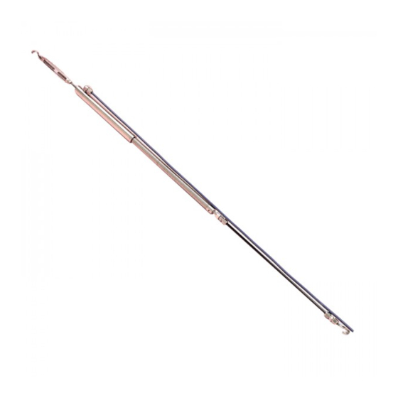
Instrument Cable measured by the transducer. The Model 4425 Convergence Meter consists of three basic components: the two anchor points, 6 mm (1/4") diameter connecting rods, and the spring-tensioned vibrating wire transducer assembly. -
Page 8: Installation
2. INSTALLATION 2.1 Preliminary Tests Upon receipt of the instrument, the gauge should be checked for proper operation (including the thermistor). See Section 3 for readout instructions. In position “B” the gauge will read around 2000 when the threaded connector is pulled out approximately 3 mm (0.125"). Figure 2 - Operation Check CAUTION! Do not extend the connector more than the range of the gauge. -
Page 9: Figure 3 - Model 4425 C
Remember that if the spring is extended beyond the range of the transducer the transducer could be damaged. Tunnel Cross Section Convergence Meter Connecting Rod Eyebolt Anchor Eyebolt Anchor Figure 3 - Model 4425 Convergence Meter Installation... -
Page 10: Lectrical Oise
50 or 60 Hz (or other frequency) noise from the power cable and this will likely cause a problem obtaining a stable reading. Contact the factory concerning filtering options available for use with the Geokon dataloggers and readouts should difficulties arise. 2.4 Removal To remove the system, loosen the turnbuckle all the way and then remove the convergence meter. -
Page 11: Cable Installation And Splicing
Splice kits recommended by Geokon incorporate casts, which are placed around the splice and are then filled with epoxy to waterproof the connections. When properly made, this type of splice is equal or superior to the cable in strength and electrical properties. Contact Geokon for splicing materials and additional cable splicing instructions. -
Page 12: Taking Readings
20 hours continuously on two AA batteries. It is designed for the readout of all Geokon vibrating wire gauges and transducers, and is capable of displaying the reading in either digits, frequency (Hz), period (µs), or microstrain (µε). The GK-404 also displays the temperature of the transducer (embedded thermistor) with a resolution of 0.1 °C. -
Page 13: Gk-405 Readout Box
3.2.2 Connecting Sensors with Bare Leads Attach the GK-403-2 flying leads to the bare leads of a Geokon vibrating wire sensor by connecting each of the clips on the leads to the matching colors of the sensor conductors, with blue representing the shield (bare). -
Page 14: Gk-403 Readout Box (Obsolete Model)
3.3.2 Connecting Sensors with Bare Leads Attach the GK-403-2 flying leads to the bare leads of a Geokon vibrating wire sensor by connecting each of the clips on the leads to the matching colors of the sensor conductors, with blue representing the shield (bare). -
Page 15: Data Reduction
4. DATA REDUCTION 4.1 Digits The basic units utilized by Geokon for measurement and reduction of data from vibrating wire Convergence Meters are “digits”. The units displayed by the GK-403, GK-404, and GK-405 in position “B” are digits. Calculation of digits is based on the following equation: Digits = �... -
Page 16: Temperature Correction
4.2 Temperature Correction In most cases, temperature correction is not necessary, since the Model 4425 Vibrating Wire Convergence Meter has a very small coefficient of thermal expansion. However, if maximum accuracy is desired or the temperature changes are extreme (>10° C) corrections may be applied. -
Page 17: Rod Stretch Correction
All of the above thermal corrections describe an expansion of components with an increase in temperature. Hence, the calculated thermal corrections must be added to the deformation calculated using Equation 2. D tcorrected = D uncorrected + D temperature Equation 5 - Thermally Corrected Deformation Calculation Experience has shown that the most stable readings are obtained when the system is at a stable temperature. -
Page 18: Correction For Sag
Increasing tensions cause the rod to elongate so that the required correction would be positive, when D tcorrected is positive. Values for S are as follows: Range Spring Rate Model Number Inches Lb./in. Newtons/mm 4425-12 ½ 5.95 4425-25 5.95 4425-50 2.98 4425-100 2.98 4425-150 1.49... - Page 19 D corrected = D uncorrected + D temperature + D rodstretch + D sag Equation 9 - Corrected Deformation Again, consider the following example from a Model 4425-12 Convergence Meter attached to 30 meters of 1/4 inch diameter graphite rod.
-
Page 20: Environmental Factors
From Equation 3: D temperature = + 17.5(0.0087 + 0.2×10 -6 × 30,000 + 0.0178) = + 0.568 mm From Equation 5: D corrected = + 4.566 + 0.568 = + 5.134 mm From Equation 7: D rodstretch = 5.95 × 5.045 × 30,000 / 31.67 × 0.117 × 10 = +0.243 mm From Equation 8: (Not required if the convergence meter is vertical) D sag =[30... -
Page 21: Troubleshooting
5. TROUBLESHOOTING Maintenance and troubleshooting of Geokon Vibrating Wire Convergence Meters are confined to periodic checks of cable connections and maintenance of terminals. The Convergence Meters contain no user serviceable components. However, consult the following list of problems and possible solutions should difficulties arise. Consult the factory for additional troubleshooting help. -
Page 22: Table 7 - Sample Resistance
Vibrating Wire Sensor Lead Grid - SAMPLE VALUES Black White Green Shield infinite infinite infinite ≅180Ω Black infinite infinite infinite ≅180Ω 3000Ω at White infinite infinite infinite 25°C 3000Ω at Green infinite infinite infinite 25°C Shield infinite infinite infinite infinite Table 7 - Sample Resistance Vibrating Wire Sensor Lead Grid - SENSOR NAME/## : Black... -
Page 23: Appendix A. Specifications
APPENDIX A. SPECIFICATIONS A.1 Model 4425 Convergence Meter Range: 12 mm 25 mm 50 mm 100 mm 150 mm 0.50 1 inch 2 inches 4 inches 6 inches inches Resolution:¹ 0.025% FSR Linearity: 0.25% FSR Accuracy: 0.1% FSR (with polynomial expression) Thermal Zero Shift:²... -
Page 24: Appendix B. Thermistor Temperature Derivation
APPENDIX B. THERMISTOR TEMPERATURE DERIVATION Thermistor Type: YSI 44005, Dale #1C3001-B3, Alpha #13A3001-B3 Resistance to Temperature Equation: A+B ( LnR ) +C(LnR) -273.2 Equation 10 - Resistance to Temperature Where; T = Temperature in °C. LnR = Natural Log of Thermistor Resistance. A = 1.4051 ×... -
Page 25: Appendix C. Swagelok Tube Fitting Instructions
APPENDIX C. SWAGELOK TUBE FITTING INSTRUCTIONS These instructions apply to one inch (25 mm) and smaller fittings. C.1 Installation 1) Fully insert the tube into the fitting until it bumps against the shoulder. Figure 7 - Tube Insertion 2) Rotate the nut until it is finger-tight. (For high-pressure applications as well as high-safety- factor systems, further tighten the nut until the tube will not turn by hand or move axially in the fitting.) 3) Mark the nut at the six o’clock position. -
Page 26: Reassembly Instructions
C.2 Reassembly Instructions Swagelok tube fittings may be disassembled and reassembled many times. Warning! Always depressurize the system before disassembling a Swagelok tube fitting. 1) Prior to disassembly, mark the tube at the back of the nut, then make a line along the nut and fitting body flats. -
Page 27: Appendix D. Example Calibration Report
APPENDIX D. EXAMPLE CALIBRATION REPORT Figure 13 - Typical 4425 Calibration Report...
Need help?
Do you have a question about the 4425 and is the answer not in the manual?
Questions and answers