Table of Contents
Advertisement
Quick Links
Instruction Manual
Model 4422
Monument Crackmeter
No part of this instruction manual may be reproduced, by any means, without the written consent of Geokon, Inc.
The information contained herein is believed to be accurate and reliable. However, Geokon, Inc. assumes no responsibility
for errors, omissions, or misinterpretation. The information herein is subject to change without notification.
Copyright ©, 2006-2017 by Geokon, Inc.
(Doc Rev F, 11/27/17)
Advertisement
Table of Contents

Subscribe to Our Youtube Channel
Related Manuals for Geokon 4422


Summary of Contents for Geokon 4422
- Page 1 Model 4422 Monument Crackmeter No part of this instruction manual may be reproduced, by any means, without the written consent of Geokon, Inc. The information contained herein is believed to be accurate and reliable. However, Geokon, Inc. assumes no responsibility for errors, omissions, or misinterpretation.
- Page 3 Upon examination by Geokon, if the unit is found to be defective, it will be repaired or replaced at no charge. However, the WARRANTY is VOID if the unit shows evidence of having been tampered with...
-
Page 5: Table Of Contents
4.2 T ..........................9 EMPERATURE ORRECTION 4.3 E ..........................10 NVIRONMENTAL ACTORS 5. TROUBLESHOOTING ............................12 APPENDIX A. SPECIFICATIONS ......................... 14 A.1 M 4422 C ..........................14 ODEL RACKMETER A.2 T ..............................14 HERMISTOR APPENDIX B. THERMISTOR TEMPERATURE DERIVATION ..............15... - Page 6 FIGURES 1 - M 4422-1 M ............ 2 IGURE ODEL ONUMENT RACKMETER ROUTABLE NCHOR 2 - M 4422-2 M ............. 3 IGURE ODEL ONUMENT RACKMETER URFACE OUNTING 3 - L ....................... 4 IGURE IGHTNING ROTECTION CHEME 4 - L GK-404 ........................5...
-
Page 7: Introduction
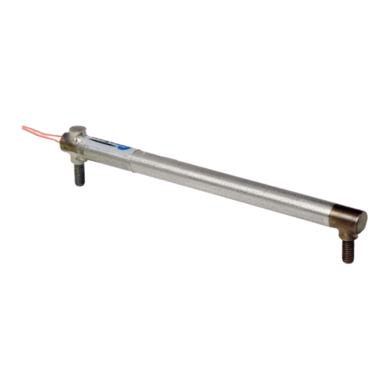
1. INTRODUCTION Geokon Model 4422 Monument Crackmeters are designed to measure movement across joints and cracks in monuments. The small size is designed to render the crackmeter as unobtrusive as possible. The shaft of the Monument Crackmeter has three small holes drilled in it. A metal pin is supplied for insertion inside one of these holes. -
Page 8: Crackmeter Installation
When the grout or epoxy has hardened then the metal pin can be removed. Figure 1 - Model 4422-1 Monument Crackmeter, Groutable Anchor Type... -
Page 9: Surface Mounting
The cable can be protected by the use of flexible conduit, which can be supplied by Geokon. Terminal boxes with sealed cable entries are available from Geokon for all types of applications. These allow many gages to be terminated at one location with complete protection of the lead wires. -
Page 10: Lightning Protection
Splice kits recommended by Geokon incorporate casts, which are placed around the splice and are then filled with epoxy to waterproof the connections. When properly made, this type of splice is equal or superior to the cable itself in strength and electrical properties. Contact Geokon for splicing materials and additional cable splicing instructions. -
Page 11: Taking Readings
3. TAKING READINGS 3.1 GK-404 Readout Box The GK-404 is a palm sized readout box that displays the vibrating wire value, as well as the temperature in degrees centigrade. 3.1.1 Operating the GK-404 Before use, attach the flying leads to the GK-404 by aligning the red circle on the silver “Lemo”... -
Page 12: Gk-405 Readout Box
3.2.2 Sensors with Bare Leads Attach the GK-403-2 flying leads to the bare leads of a Geokon vibrating wire sensor by connecting each of the clips on the leads to the matching colors of the sensor conductors, with blue representing the shield (bare). -
Page 13: Gk-403 Readout Box (Obsolete Model)
3.3.2 Connecting Sensors with Bare Leads Attach the GK-403-2 flying leads to the bare leads of a Geokon vibrating wire sensor by connecting each of the clips on the leads to the matching colors of the sensor conductors, with blue representing the shield (bare). -
Page 14: Data Reduction
4. DATA REDUCTION 4.1 Displacement Calculation The basic unit utilized by Geokon for measurement and reduction of data from Vibrating Wire Displacement Transducers is "digits". Calculation of digits is based on the following equation: Digits = � � x 10... -
Page 15: Temperature Correction
4.2 Temperature Correction Because Geokon’s Vibrating Wire Displacement Transducers have a small coefficient of thermal expansion, in many cases correction may not be necessary. However, if maximum accuracy is desired, or the temperature changes are extreme (>10 °C), a correction may be applied based on the following equation: ) ×... -
Page 16: Environmental Factors
The following example shows that corrections for temperature change are usually small and can often be ignored. = 4773 digits = 4589 digits = 20.3 °C = 32.9 °C G = 0.001077 mm/digit K = (((4589 × 0.00073) + 0.583) × 0.001077) = 0.00424 ) ×... -
Page 17: Figure 6 - Typical 4422 M
Figure 6 - Typical 4422 Monument Crackmeter Calibration Sheet... -
Page 18: Troubleshooting
Gages should not be opened in the field. Should difficulties arise, consult the following list of problems and possible solutions. Return any faulty gages to the factory. For additional troubleshooting and support, contact Geokon. Symptom: Thermistor resistance is too high ... -
Page 19: Table 4 - Sample Resistance
Vibrating Wire Sensor Lead Grid - SAMPLE VALUES Black White Green Shield ≅50Ω infinite infinite infinite ≅50Ω Black infinite infinite infinite 3000Ω at White infinite infinite infinite 25°C 3000Ω at Green infinite infinite infinite 25°C Shield infinite infinite infinite infinite Table 4 - Sample Resistance Vibrating Wire Sensor Lead Grid - SENSOR NAME/## Black... -
Page 20: Appendix A. Specifications
APPENDIX A. SPECIFICATIONS A.1 Model 4422 Crackmeter Range: 4 mm / 0.16 inches Resolution:¹ 0.025% FSR 0.25% FSR Linearity: Thermal Zero Shift:² < 0.05% FSR/°C Stability: < 0.2%/yr (under static conditions) 115% FSR Overrange: Temperature Range: -40 to +60 °C -40 to 120 °F... -
Page 21: Appendix B. Thermistor Temperature Derivation
APPENDIX B. THERMISTOR TEMPERATURE DERIVATION Thermistor Type: YSI 44005, Dale #1C3001-B3, Alpha #13A3001-B3 Resistance to Temperature Equation: A+B ( LnR ) +C(LnR) -273.2 Equation 5 - Resistance to Temperature Where; T = Temperature in °C. LnR = Natural Log of Thermistor Resistance. A = 1.4051 ×...
Need help?
Do you have a question about the 4422 and is the answer not in the manual?
Questions and answers