Table of Contents
Advertisement
Quick Links
Instruction Manual
Model 4400
V W Embedment Jointmeter
No part of this instruction manual may be reproduced, by any means, without the written consent of
Geokon, Inc.
The information contained herein is believed to be accurate and reliable. However, Geokon, Inc. assumes
no responsibility for errors, omissions or misinterpretation. The information herein is subject to change
without notification.
Copyright © 1985-2016 by Geokon, Inc.
(Doc Rev J, 11/10/16)
Advertisement
Table of Contents

Related Manuals for Geokon 4400


Summary of Contents for Geokon 4400
- Page 1 No part of this instruction manual may be reproduced, by any means, without the written consent of Geokon, Inc. The information contained herein is believed to be accurate and reliable. However, Geokon, Inc. assumes no responsibility for errors, omissions or misinterpretation. The information herein is subject to change without notification.
- Page 3 Upon examination by Geokon, if the unit is found to be defective, it will be repaired or replaced at no charge. However, the WARRANTY is VOID if the unit shows evidence of having been tampered with or...
-
Page 5: Table Of Contents
ORRECTION 4.3. E ........................10 NVIRONMENTAL ACTORS 5. TROUBLESHOOTING ..........................11 APPENDIX A - SPECIFICATIONS ....................... 12 A.1 M 4400 E ....................12 ODEL MBEDMENT OINTMETER A.2 T ) ....................... 12 HERMISTOR PPENDIX ALSO ... - Page 6 LIST of FIGURES, TABLES and EQUATIONS 1 - M 4400 V ..............1 IGURE ODEL IBRATING MBEDMENT OINTMETER 2 - S ......................... 2 IGURE OCKET NSTALLATION ......................3 IGURE HOWING NGAGED IN 4 – C ............... 4...
-
Page 7: Introduction
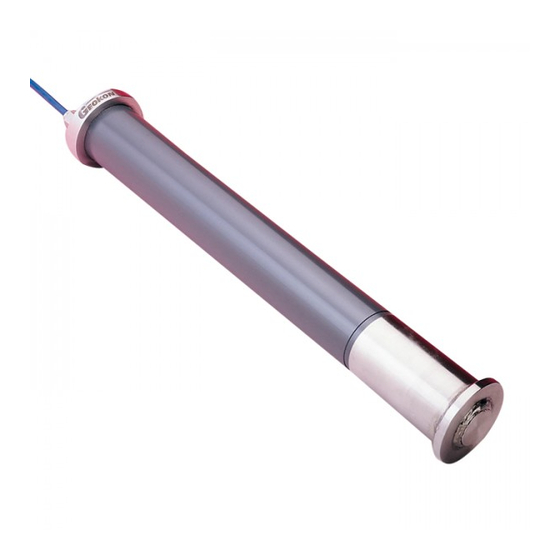
1. INTRODUCTION Geokon Model 4400 Vibrating Wire Embedment Jointmeters are intended primarily for the measurement of joint openings between lifts or sections in mass concrete or across fracture zones in fully grouted boreholes. The instrument consists of a vibrating wire sensing element in series with a heat treated, stress relieved spring which is connected to the wire at one end and a connecting rod at the other. -
Page 8: Installation
2. INSTALLATION 2.1. Preliminary Tests Upon receipt of the instrument, the gage should be checked for proper operation (including the thermistor). See Section 3 for readout instructions. In position "B" the gage will read around 2000 when the threaded connector is pulled out approximately 3 mm (0.125"). Do not extend the connector more than the range of the gage. -
Page 9: Installing The Jointmeter
The protective socket plug is supplied with a ¼-20 x 1 inch bolt which can be used to bolt the socket to the forms. See Figure 2. 2.2.2. Installing the Jointmeter. After the forms have been stripped and socket exposed, the socket plug should be removed using the socket plug bolt or, if necessary, one of the eyebolt supplied. -
Page 10: Setting The Initial Rreading
2.2.3.2 Model 4400-12 The above procedure for the longer range models is not recommended for the 4400-12 model. Here the danger of over-ranging the sensor due to the sudden release, when pulling the gage out, is too great. So leave the transducer as is. The natural compression of the gage a will be enough to allow for any small amount of joint closure. -
Page 11: Cable Installation
The instrument cables will pick up the 50 or 60 Hz (or other frequency) noise from the power cable and this will likely cause a problem obtaining a stable reading. Contact the factory concerning filtering options available for use with the Geokon dataloggers and readouts should difficulties arise. -
Page 12: Taking Readings
3. TAKING READINGS 3.1. Operation of the GK-403 Readout Box The GK-403 can store gage readings and also apply calibration factors to convert readings to engineering units, ie. inches or millimeters. Consult the GK-403 Instruction Manual for additional information on Mode "G" of the Readout. The following instructions will explain taking gage measurements using Mode "B". -
Page 13: Measuring Temperatures
3.3. Measuring Temperatures Each Vibrating Wire Embedment Jointmeter is equipped with a thermistor for reading temperature. The thermistor gives a varying resistance output as the temperature changes. Usually the white and green leads are connected to the internal thermistor. 1. Connect an ohmmeter to the two thermistor leads coming from the jointmeter. (Since the resistance changes with temperature are so large, the effect of cable resistance is usually insignificant.) 2. -
Page 14: Data Reduction
4. DATA REDUCTION 4.1. Deformation Calculation The basic units utilized by Geokon for measurement and reduction of data from Vibrating Wire Jointmeters are "digits". The units displayed by the GK-401, GK-402, and GK-403 in position "B" are digits. Calculation of digits is based on the following equation;... -
Page 15: Temperature Correction
4.2. Temperature Correction The Model 4400 Vibrating Wire Jointmeter has a very small coefficient of thermal expansion so in most cases correction is not necessary. However, if maximum accuracy is desired or the temperature changes are extreme (>10° C) corrections may be applied. The temperature coefficient of the mass in which the Jointmeter is embedded should also be taken into account. -
Page 16: Environmental Factors
Consider the following example using a Jointmeter with a 25 mm range transducer. = 3150 digits = 6000 digits = 15.3° C = 20.8° C G = 0.00356 mm/digit K = ((6000 0.000369) + 0.572) 0.00356 = 0.0099 ... -
Page 17: Troubleshooting
5. TROUBLESHOOTING Maintenance and troubleshooting of Geokon Vibrating Wire Embedment Jointmeters is confined to periodic checks of cable connections and maintenance of terminals. Once installed, the Jointmeters are usually inaccessible and remedial action is limited. Consult the following list of problems and possible solutions should difficulties arise. Consult the factory for additional troubleshooting help. -
Page 18: Appendix A - Specifications
APPENDIX A - SPECIFICATIONS A.1 Model 4400 Embedment Jointmeter Range:¹ 12 mm 25 mm 50 mm 0.50 inches 1 inch 2 inches Resolution: 0.025% FSR Linearity: 0.25% FSR 0.5% FSR Accuracy: (0.1% FSR with a polynomial expression) Thermal Zero Shift: <... -
Page 19: Appendix B - Thermistor Temperature Derivation
APPENDIX B - THERMISTOR TEMPERATURE DERIVATION Thermistor Type: YSI 44005, Dale #1C3001-B3, Alpha #13A3001-B3 Resistance to Temperature Equation: 273 2 A B LnR C LnR Equation B-1 Convert Thermistor Resistance to Temperature T Temperature in C. Where;...
Need help?
Do you have a question about the 4400 and is the answer not in the manual?
Questions and answers