Table of Contents
Advertisement
Quick Links
Instruction Manual
Model 4420
VW Crackmeter
No part of this instruction manual may be reproduced, by any means, without the written consent of Geokon, Inc.
The information contained herein is believed to be accurate and reliable. However, Geokon, Inc. assumes no responsibility
for errors, omissions or misinterpretation. The information herein is subject to change without notification.
Copyright © 1986, 1996, 2004, 2006, 2007, 2008 by Geokon, Inc.
(Doc Rev N, 9/08)
Advertisement
Table of Contents

Subscribe to Our Youtube Channel
Related Manuals for Geokon 4420


Summary of Contents for Geokon 4420
- Page 1 Model 4420 VW Crackmeter No part of this instruction manual may be reproduced, by any means, without the written consent of Geokon, Inc. The information contained herein is believed to be accurate and reliable. However, Geokon, Inc. assumes no responsibility for errors, omissions or misinterpretation.
- Page 4 The buyer's sole remedy for any breach of this agreement by Geokon, Inc. or any breach of any warranty by Geokon, Inc. shall not exceed the purchase price paid by the purchaser to Geokon, Inc.
-
Page 6: Table Of Contents
........................12 EMPERATURE ORRECTION 4.3. E ........................13 NVIRONMENTAL ACTORS 5. TROUBLESHOOTING ..........................13 APPENDIX A - SPECIFICATIONS ....................... 14 A.1 M 4420 C ........................15 ODEL RACKMETER A.2 T ............................. 15 HERMISTOR APPENDIX B - THERMISTOR TEMPERATURE DERIVATION ............15... - Page 7 LIST of FIGURES, TABLES and EQUATIONS Page 1: M 4420-1-50/100/150/200/300 V ..........1 IGURE ODEL IBRATING RACKMETER 2 - M 4420-1-12/25 D .......................1 IGURE ODEL ETAIL 3 - A .......................2 IGURE NCHOR YPES WITH IMENSIONS 1 - C ..................3 ABLE RACKMETER...
-
Page 9: Introduction
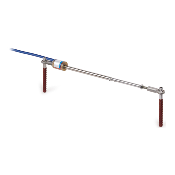
Figure 1: Model 4420-1-50/100/150/200/300 Vibrating Wire Crackmeter The Model's 4420-12 and 4420-25 differ slightly from the standard Crackmeter in that they provide for adjustment of the setting distance with a threaded extension rod and locking nut. -
Page 10: Installation
3000 ohms at 25° (see Table B-1), and between any conductor and the shield should exceed 2 megohms. 2.2. Crackmeter Installation Three types of anchors are available from the factory for installing the Model 4420 Vibrating Wire Crackmeter. Figure 3 - Anchor Types with Dimensions The weldable fixture is designed to install the Crackmeter on steel members. - Page 11 The alignment pin on the transducer shaft and slot on the body serve as a guide for alignment. Special note regarding installation of the Model's 4420-1-12 or 4420-1-25: If the reading is not in the proper range after installation additional adjustment is provided for by the inclusion of a threaded extension and locking nut as depicted in Figure 2.
-
Page 12: Installation Using Weldable Fixtures
Figure 4 - Installation using Weldable Fixtures Installation instructions; (See section 2.2 for special instructions re Models 4420-1-12 and 4420-1-25) 1. Determine proper setting distance using figures in Table 1 or the readings on the calibration sheet. Prepare the surface (grinding, sanding, etc.) of the steel around the area of each weldable fixture. -
Page 13: Installation Using Expansion Anchors
Figure 6 - Installation using Expansion Anchors Installation instructions; (See section 2.2 for special instructions re Models 4420-1-12 and 4420-1-25) 1. Determine proper setting distance using figures from Table 1 or the readings on the calibration sheet. Using a masonry drill or other suitable equipment, drill two 3/8 inch, (or 10mm), diameter holes 1¼", (32mm), deep at the proper locations. -
Page 14: Cable Installation
2.5. Lightning Protection The Model 4420 Vibrating Wire Crackmeter, unlike numerous other types of instrumentation available from Geokon, do not have any integral lightning protection components, i.e. transzorbs or plasma surge arrestors. Usually this is not a problem however, if the instrument cable is exposed, it may be appropriate to install lightning protection components, as the transient could travel down the cable to the gage and possibly destroy it. -
Page 15: Taking Readings
Structure Terminal Box/Multiplexer Crack Model 4420 Crackmeter Instrument Cable (usually buried) LAB-3 Enclosure LAB-3 Board Surface Ground Connections Figure 7 - Lightning Protection Scheme 3. TAKING READINGS 3.1. Operation of the GK-401 Readout Box The GK-401 is a basic readout for all vibrating wire gages. -
Page 16: Operation Of The Gk404 Readout Box
Mode "G" of the Readout. The following instructions will explain taking gage measurements using Modes "B" and "F" (similar to the GK-401 switch positions "B" and "F"). Connect the Readout using the flying leads or in the case of a terminal station, with a connector. -
Page 17: Measuring Temperatures
Note: The GK-403 and GK-404 readout boxes will read the thermistor and display temperature in °C automatically. 4. DATA REDUCTION 4.1. Deformation Calculation The basic units utilized by Geokon for measurement and reduction of data from Vibrating Wire Crackmeters are "digits". Calculation of digits is based on the following equation; ⎛ ⎞... - Page 18 For example, the initial reading R , at installation of a crackmeter is 2500 digits. The current reading, R , is 6000. The gage factor is 0.004457 mm/digit. The deformation change is; − × = (6000 2500) 0.004457 = +15.60 mm uncorrected Note that increasing readings (digits) indicate increasing extension.
- Page 19 Figure 8 - Typical Crackmeter Calibration Sheet...
-
Page 20: Temperature Correction
4.2. Temperature Correction The Model 4420 Vibrating Wire Crackmeters have a small coefficient of thermal expansion so in many cases correction may not be necessary. However, if maximum accuracy is desired or the temperature changes are extreme (>10° C) corrections may be applied. The temperature coefficient of the mass or member to which the Crackmeter is attached should also be taken into account. -
Page 21: Environmental Factors
5. TROUBLESHOOTING Maintenance and troubleshooting of Geokon Vibrating Wire Crackmeters is confined to periodic checks of cable connections and maintenance of terminals. The transducers themselves are sealed and cannot be opened for inspection. However, note the following problems and possible solutions should difficulties arise. -
Page 22: Appendix A - Specifications
Is the cable cut or crushed? This can be checked with an ohmmeter. Nominal resistance between the two transducer leads (usually red and black leads) is 180Ω, ±10Ω. Remember to add cable resistance when checking (22 AWG stranded copper leads are approximately 14.7Ω/1000' or 48.5Ω/km). -
Page 23: Model 4420 Crackmeter
A.1 Model 4420 Crackmeter Range: 12 mm 25 mm 50 mm 100 mm 150 mm 200mm 300m 0.50 " 1" 2" 4 " 6 " 8" m 12" Resolution:¹ 0.025% FSR 0.25% FSR Linearity: Thermal Zero Shift:² < 0.05% FSR/°C Stability: <... - Page 24 Resistance to Temperature Equation: − 273 2 A B LnR C LnR Equation B-1 Convert Thermistor Resistance to Temperature T = Temperature in °C. Where: LnR = Natural Log of Thermistor Resistance A = 1.4051 × 10 (coefficients calculated over the −50 to +150° C. span) B = 2.369 ×...
Need help?
Do you have a question about the 4420 and is the answer not in the manual?
Questions and answers