Table of Contents

Related Manuals for Wenglor P1PY0 Series


Summary of Contents for Wenglor P1PY0 Series
- Page 1 P1PY0xx High-Performance Distance Sensors Operating Instructions Translation of the Original Operating Instruction Subject to change without notice Available as PDF version only Version: 1.1.0 Status: 01.04.2019 www.wenglor.com...
-
Page 2: Table Of Contents
Table of Contents 1. General ...........................3 1.1 Information Concerning these Instructions ..................... 3 1.2 Explanations of Symbols ......................... 3 1.3 Limitation of Liability ..........................4 1.4 Copyrights ..............................4 2. For Your Safety ........................5 2.1 Use for Intended Purpose ........................5 2.2 Use for Other than the Intended Purpose .................... -
Page 3: General
• The product is subject to further technical development, and thus the information contained in these operating instructions may also be subject to change. The current version can be found at www.wenglor.com in the product’s separate download area. NOTE! The operating instructions must be read carefully before using the product and must be kept on hand for later reference. -
Page 4: Limitation Of Liability
• wenglor assumes no liability for printing errors or other inaccuracies contained in these operating instruc- tions, unless wenglor was verifiably aware of such errors at the point in time at which the operating instruc- tions were prepared. -
Page 5: For Your Safety
• The product is not suitable for use in potentially explosive atmospheres. • The product may only be used with accessories supplied or approved by wenglor, or combined with approved products. A list of approved accessories and combination products can be accessed at www.wenglor.com on the product detail page. -
Page 6: Personnel Qualifications
• In the event of possible changes, the respectively current version of the operating instruc- tions can be accessed at www.wenglor.com in the product’s download area. • Read the operating instructions carefully before using the product. -
Page 7: Technical Data
3. Technical Data Optical Data Working range 0...3000 mm Setting range 200...3000 mm Switching hysteresis < 15 mm Light source Laser (red) Wavelength 660 nm Service life (ambient temp. = +25° C) 100000 h Laser class (EN 60825-1) Beam Divergence <... -
Page 8: Spot Diameter
3.1 Spot diameter Working distance Spot diameter 5 mm 9 mm Table 1 3.2 Switching Distance Deviation Typical characteristic curve based on Kodak white (90% remission). P1PY 10,0 -2,5 -5,0 -7,5 1000 1500 2000 2500 3000 Sr/mm Sr = switching distance dSr = change in switching distance Black, 6 % remission Gray, 18 % remission... -
Page 9: Accessory Products
3.3 Accessory Products wenglor can provide you with suitable connection technology for your product. Suitable connection technology no. IO-Link master wTeach2 software DNNF005 Protective Housing ZSV-0x-01 Set Protective Housing ZSP-NN-02 High-Performance Distance Sensors... -
Page 10: Layout
3.4 Layout P1PY001/P1PY003 P1PY002/P1PY004 1 = receiver diode 2 = emitter diode M4 screw = 0,5 Nm Dimensions specified in mm (1 mm = 0.03937”) Technical Data... -
Page 11: Control Panel
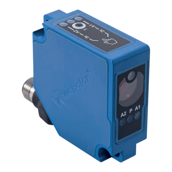
3.5 Control Panel 06 = teach-in key 5a = switching status display, A1 6a = switching status display, A2 68 = supply power indicator 3.6 Scope of Delivery • Sensor • Commissioning Instructions • Mounting-Set 14 • Mounting-Set 44 4. Transport and Storage 4.1 Transport Upon receipt of shipment, the goods must be inspected for damage in transit. -
Page 12: Installation And Electrical Connection
5. Installation and Electrical Connection 5.1 Installation • Protect the product from contamination during installation. • Observe all applicable electrical and mechanical regulations, standards, and safety rules. • Protect the product against mechanical influences. • Make sure that the sensor is mounted in a mechanically secure fashion. •... -
Page 13: Diagnostics
DANGER! Risk of personal injury or property damage due to electric current! Voltage conducting parts may cause personal injury or damage to equipment. • The electric device may only be connected by appropriately qualified personnel. 5.3 Diagnostics Causes for Triggering the Contamination Warning (A1/A2 Continuous blinking LED): Display LED Diagnosis/Cause Elimination... - Page 14 • Shut down the machine. • Analyze and eliminate the cause of error with the help of the diagnostics information. • If the error cannot be eliminated, please contact wenglor’s support department. • Do not operate in case of indeterminate malfunctioning.
-
Page 15: Settings
6. Settings The switching distance to the object can be taught in for both outputs by pressing the teach-in key on the sensor (foreground teach-in). Sensor Teach-in distance Object Switching point Foreground Teach-In for Switching Output 1 1. Mount the sensor in accordance with the mounting instructions. 2. -
Page 16: Settings Via Io-Link
In addition to foreground teach-in (default setting), there’s also a background teach-in option for both outputs. Additionally, there’s also a window teach-in option for both outputs. Process and parameters data, as well as the interface protocol and the IODD, can be found at www.wenglor. com in the product’s separate download area. -
Page 17: Locking
7.3 Locking If 18 to 30 V DC is continuously applied to the teach-in input, the teach-in key is locked and protected against inadvertent changes. 1. Change the A1/A2/E3 pin function to external teach-in. 2. Permanently connect pin A1/A2/E3 to voltage within a range of 18 to 30 V DC. 3. -
Page 18: Test Mode
01.04.19 New section “3.2 Switching Distance Deviation”, page 8 “3.3 Accessory Products”, page 9 10.3 EU Declaration of Conformity The EU declaration of conformity can be found on our website at www.wenglor.com in the product’s down- load area. Maintenance Instructions...
Need help?
Do you have a question about the P1PY0 Series and is the answer not in the manual?
Questions and answers